

Page 1
FARO Laser Scanner LS
420HE/840HE/880HE
User’s Manual
Page 2

User’s manual FARO Laser Scanner LS 2
© 2007 FARO Scanner Production
Copyright © 2007 FARO Technologies Inc. All rights reserved.
No part of this publication may be reproduced, or transmitted in any form or by any
means without written permission of FARO Technologies Inc.
FARO TECHNOLOGIES INC. MAKES NO WARRANTY, EITHER EXPRESS OR
IMPLIED, INCLUDING BUT NOT LIMITED TO ANY IMPLIED WARRANTIES OF
MERCHANTABILITY OR FITNESS FOR A PARTICULAR PURPOSE, REGARDING
FARO LASER SCANNER LS AND ITS MATERIALS, AND MAKES SUCH
MATERIALS AVAILABLE SOLELY ON AN “AS-IS” BASIS. IN NO EVENT SHALL
FARO TECHNOLOGIES INC. BE LIABLE TO ANYONE FOR SPECIAL,
COLLATERAL, INCIDENTAL, OR CONSEQUENTIAL DAMAGES IN CONNECTION
WITH OR ARISING OUT OF THE PURCHASE OR USE OF FARO LASER
SCANNER LS OR ITS MATERIALS. THE SOLE AND EXCLUSIVE LIABILITY TO
FARO TECHNOLOGIES INC., REGARDLESS OF THE FORM OF ACTION, SHALL
NOT EXCEED THE PURCHASE PRICE OF THE MATERIALS DESCRIBED
HEREIN.
The information contained in this manual is subject to change without notice and
does not represent a commitment on the part of FARO Technologies Inc.
FARO Technologies Inc. Internal Control File Location:
X:\CONTROL\RECORDS\05MANUFA\PARTSPEC\7 Software\E240 FARO Laser Scanner LS Manual EN.pdf
Page 3

User’s manual FARO Laser Scanner LS 3
© 2007 FARO Scanner Production
Table of contents
1 Introduction 5
2 Safety Precautions 6
2.1 General Safety Information................................................................................................ 6
2.2 Electrical Safety................................................................................................................. 7
2.3 Laser Safety...................................................................................................................... 7
2.4 Mechanical Security.......................................................................................................... 9
3 Equipment 10
4 Your first scan - step-by-step 11
4.1 Setup of the FARO Laser Scanner LS............................................................................. 11
4.1.1 Step 1 - Setting up the tripod................................................................................................ 11
4.1.2 Step 2 – Attaching the Tripod Head..................................................................................... 11
4.1.3 Step 3 – Fixing the FARO Laser Scanner LS..................................................................... 12
4.1.4 Step 4 – Connecting the FARO Laser Scanner LS............................................................ 13
4.1.5 Step 5 - Switching on the scanner....................................................................................... 15
4.2 Installing and using the software...................................................................................... 15
4.2.1 Step 6 – (Software installation)............................................................................................ 15
4.2.2 Step 7 – Establishing an Ethernet connection to the scanner........................................... 15
4.3 Starting a scan................................................................................................................ 17
4.3.1 Step 8 – Unlocking the laser................................................................................................ 17
4.3.2 Step 9 – Scanning................................................................................................................. 17
4.3.3 Step 10 – Shutting down the scanner.................................................................................. 17
5 Shutdown of the FARO Laser Scanner LS 18
6 The Software FARO Record 19
6.1 Installation....................................................................................................................... 19
6.2 License............................................................................................................................ 19
6.3 The scan bar................................................................................................................... 20
6.3.1 Scanner Parameter............................................................................................................... 20
6.3.2 Scanner Settings................................................................................................................... 26
6.3.3 Scanner Selection................................................................................................................. 26
6.4 The Scanner menu.......................................................................................................... 27
6.5 Status bar........................................................................................................................ 28
7 Color Option 29
7.1 Initial Setup of the camera............................................................................................... 29
7.2 Setup before scanning..................................................................................................... 29
7.3 Scanning with color......................................................................................................... 32
7.4 Applying the pictures to the scan..................................................................................... 34
8 Using FARO Record Mobile with a PDA 35
8.1 Setting up the WLAN connection..................................................................................... 35
8.1.1 FARO LaserScanner LS....................................................................................................... 35
8.1.2 PDA........................................................................................................................................ 36
8.2 Setting up Opera............................................................................................................. 38
8.3 Connecting to the Scanner .............................................................................................. 39
8.4 FARO Record Mobile Pages Description ......................................................................... 40
8.4.1 Scan Page............................................................................................................................. 40
Page 4

User’s manual FARO Laser Scanner LS 4
© 2007 FARO Scanner Production
8.4.2 Settings Page........................................................................................................................ 41
8.4.3 Color Page............................................................................................................................. 41
8.4.4 Project Page.......................................................................................................................... 42
8.4.5 Operator Page....................................................................................................................... 42
8.4.6 Storage Page......................................................................................................................... 43
8.4.7 Scans Page........................................................................................................................... 43
8.5 Viewing scans................................................................................................................. 43
8.6 Auxiliary Files in the Scans Network Drive....................................................................... 45
9 Cleaning Instructions for optics 46
9.1 Slightly contaminated mirror............................................................................................. 47
9.2 Greatly contaminated mirror............................................................................................. 47
9.3 Cleaning the receiver lens............................................................................................... 48
9.4 Suppliers......................................................................................................................... 48
10 Appendix 49
10.1 FARO Laser Scanner LS error messages........................................................................ 49
10.2 FARO Laser Scanner LS data and power cable............................................................... 49
11 Product Environmental Information 51
Page 5
User’s manual FARO Laser Scanner LS 5
© 2007 FARO Scanner Production
1 Introduction
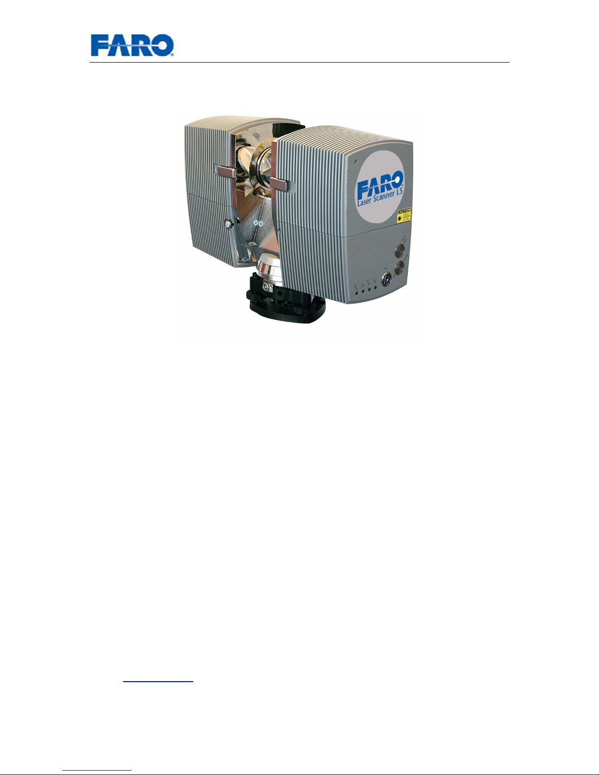
Fig.1 FARO Laser Scanner LS
The FARO Laser Scanner LS is a precise measuring instrument producing
photorealistic three dimensional images. The main features are
• high accuracy
• high resolution
• high speed
• modularity
A list of possible applications can be found on the FARO webpage
http://www.faro.com.
This manual provides an introduction to the FARO Laser Scanner LS.
As a minimum requirement, read at least the safety information and the step-by-step
guide before using the scanner!
Faro Scanner Production GmbH
Lingwiesenstraße 11/2
D-70825 Korntal-Münchingen
Tel.: +49 (0)7150 9797400
Fax: +49 (0)7150 97979400
Mail: [email protected]
Web: www.faro.com
Page 6

User’s manual FARO Laser Scanner LS 6
© 2007 FARO Scanner Production
2 Safety Precautions
2.1 General Safety Information
WARNING:
• Do not expose this appliance to rain or moisture. For outdoor use, please
ensure that the device is protected against rain or spray water. Do not use the
product near water. Humidity must not be higher than 80%. Liquid entering the
product’s enclosure can lead to severe damage, fire or electric shocks.
• When the product is transferred from a cold to a warm environment, water
may condense on some elements inside the product. Wait till the
condensation water is dried by itself before switching on the FARO Laser
Scanner LS.
• Do not open the housing. You can damage the product by opening the
housing and the product’s warranty may be affected.
• Read this User’s Manual carefully and retain it. Adhere to all warnings and
follow the instructions step by step.
• Do not use parts which have not been supplied or recommended by FARO.
• Servicing and repair must only be done by qualified service personnel
authorized by FARO.
• Unplug this product from the power outlet and refer servicing to qualified
service personnel under the following conditions:
o The power-supply cord or plug is damaged.
o The product has been exposed to rain or water or other liquids.
o The product has been dropped or damaged in any way.
o Objects have fallen into the product
o The product does not operate normally by following the operating
instructions.
o The product exhibits a distinct change in performance.
o When the required service and calibration date is due
• Only replacement parts authorized by FARO may be used according to the
instructions obtained from FARO.
• Do not expose the product to extreme temperatures. The ambient
temperature must not be lower or higher than given in the specifications. Do
not use the FARO Laser Scanner LS near heat sources such as radiators,
heat registers or other products (including amplifiers) that produce heat.
• Do not use the FARO Laser Scanner LS in vicinity of strong magnetic or
electrical fields.
Page 7
User’s manual FARO Laser Scanner LS 7
© 2007 FARO Scanner Production
2.2 Electrical Safety
• Do not open the housing. Dangerous high voltages are present inside the
enclosure. Only qualified service personnel should open the cabinet. Never
push objects of any kind into this product through openings as they may touch
dangerous voltage points or short-out parts. This could result in a fire or
electric shock and damage the product.
• This product should be operated only from the power source supplied or
recommended by FARO. Please ensure that the specifications of the AC
converter are met by your line voltage. If you do not know the power line
voltage in your area, please ask your local power company.
• This product may be equipped with a three-wire grounding-type plug, a plug
having a third (grounding) pin. This plug will only fit into a grounding-type
power outlet. This is a safety feature. If you are unable to insert the plug into
the outlet, contact your electrician to replace your outlet (and not the plug).
2.3 Laser Safety
CAUTION: This product employs a laser system. To prevent direct exposure to the
laser beam, do not try to open the enclosure.
The FARO Laser Scanner LS should only be operated by trained personnel.
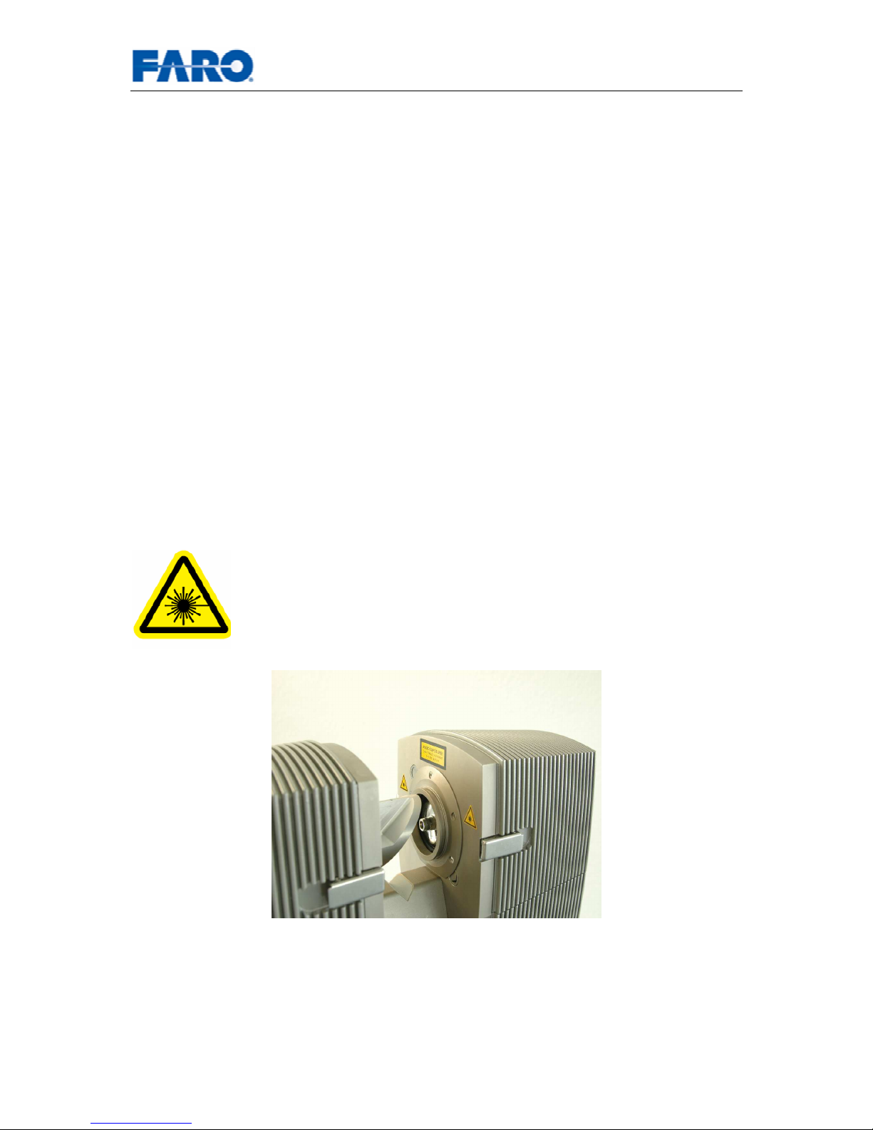
The outlet of the laser beam is marked by stickers. If the laser is
armed, do not look into the direction of the laser without wearing laser
safety glasses. Viewing the laser beam without protection from a
short distance may pose an eye hazard. Do no stare into the beam or
view directly with optical instruments. Do not place mirrors or objects
with reflective surface into the beam.
Page 8
User’s manual FARO Laser Scanner LS 8
© 2007 FARO Scanner Production
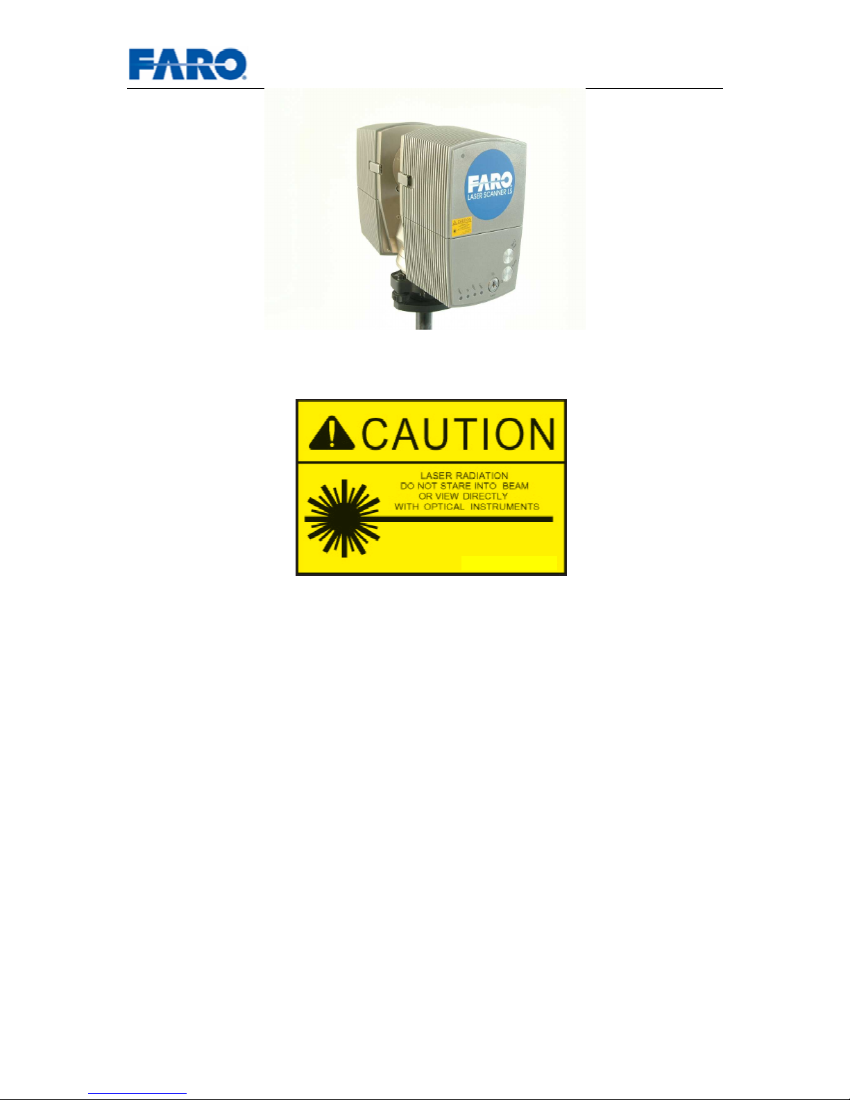
Fig.2 Safety Sticker
When operating the FARO Laser Scanner LS, you must adhere to the eye safety
distance (nominal ocular hazard distance NOHD). The eye safety distance is
dependent on the requested resolution (see chapter 6.3.1.2.) and on the laser power.
Personnel working in distances shorter than the eye safety distance must wear laser
safety glasses. Prevent people without laser safety glasses from entering this area
(e.g. by using a safety fence).
HE20: 20 mW, 785 nm
Max. Pulse: 0.0042 sec
CLASS 3R LASER PRODUCT
Page 9

User’s manual FARO Laser Scanner LS 9
© 2007 FARO Scanner Production
2.4 Mechanical Security
• The FARO Laser Scanner LS may only be used when set on a flat and stable
surface. People can be hit and severe injuries can be caused by an overturn
of the FARO Laser Scanner LS. Only use equipment recommended by FARO
and follow the setup instructions of the manufacturer.
• If using a cart, move the setup with special care. Never move the cart by
pulling at the data or power cables. Pushing or pulling of the cart with too
much force, sudden stops or an uneven surface can cause an upset of the
scanner.
• The scanner is rotating clockwise up to 360 degrees when performing a scan.
Ensure that the case of the scanner can rotate freely and does not hit any
objects during the scan.
• While scanning and for a short period after the scan, the mirror unit is rotating
with high speed. Do not touch the rotating mirror unit with your hands or any
objects. You could hurt yourself and cause damage to the scanner.
Page 10
User’s manual FARO Laser Scanner LS 10
© 2007 FARO Scanner Production
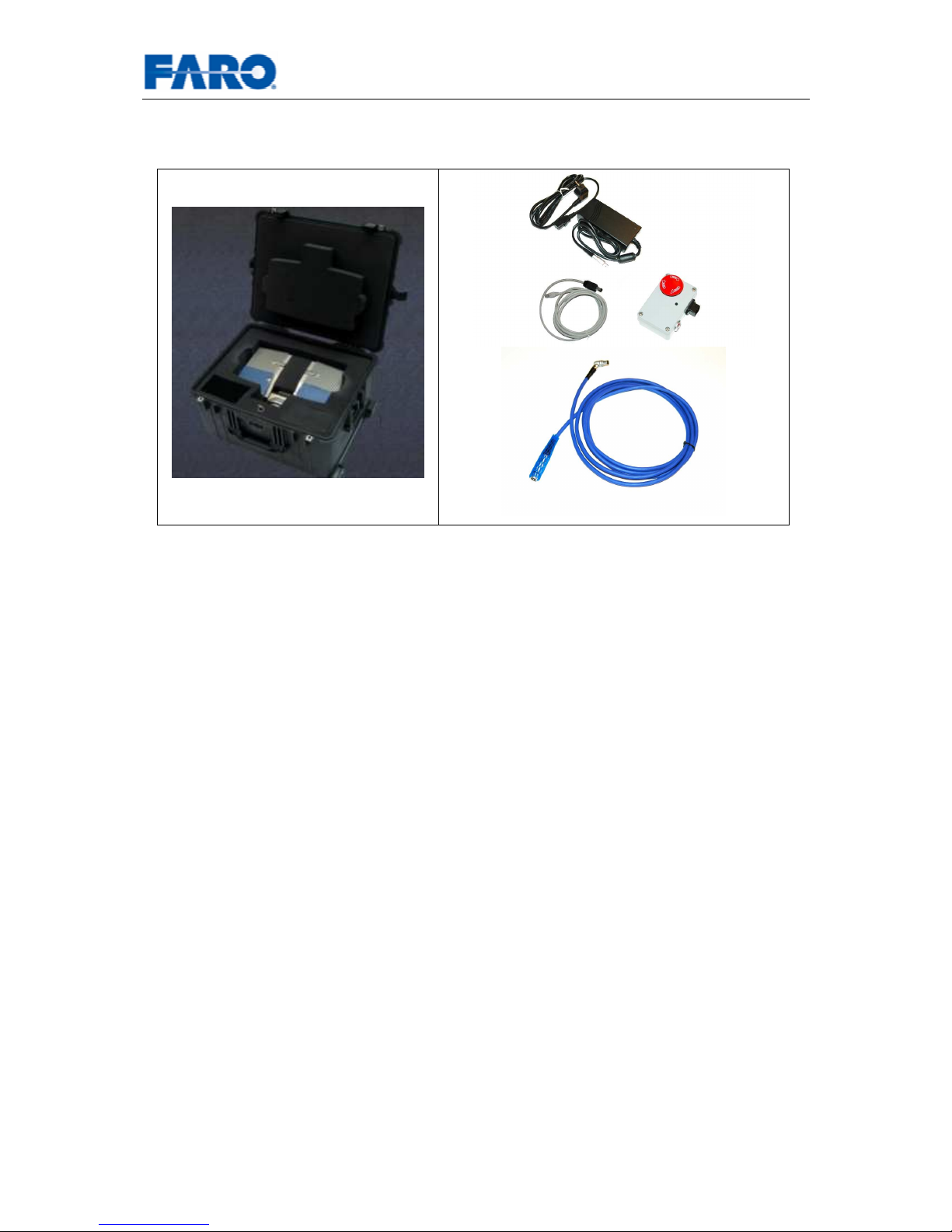
3 Equipment
Fig.3 Equipment
Check that all of the equipment that is required for the operation of this product is
available, as listed below.
• Scanner carry case
• FARO Laser Scanner LS 420HE/840HE/880HE
• Laser lock key
• Scanner data and power cable
• Scanner connector box
• Power supply unit with cable
• Ethernet cable
• Tribrach
• CD with FARO Record software
• User’s manual
• Battery pack (optional)
• Tripod (optional)
Retain all packing material as you may require them at a later stage.
Page 11
User’s manual FARO Laser Scanner LS 11
© 2007 FARO Scanner Production
4 Your first scan - step-by-step
This chapter will guide you step-by-step from setting up the scanner to doing the first
scan using FARO Record.
4.1 Setup of the FARO Laser Scanner LS
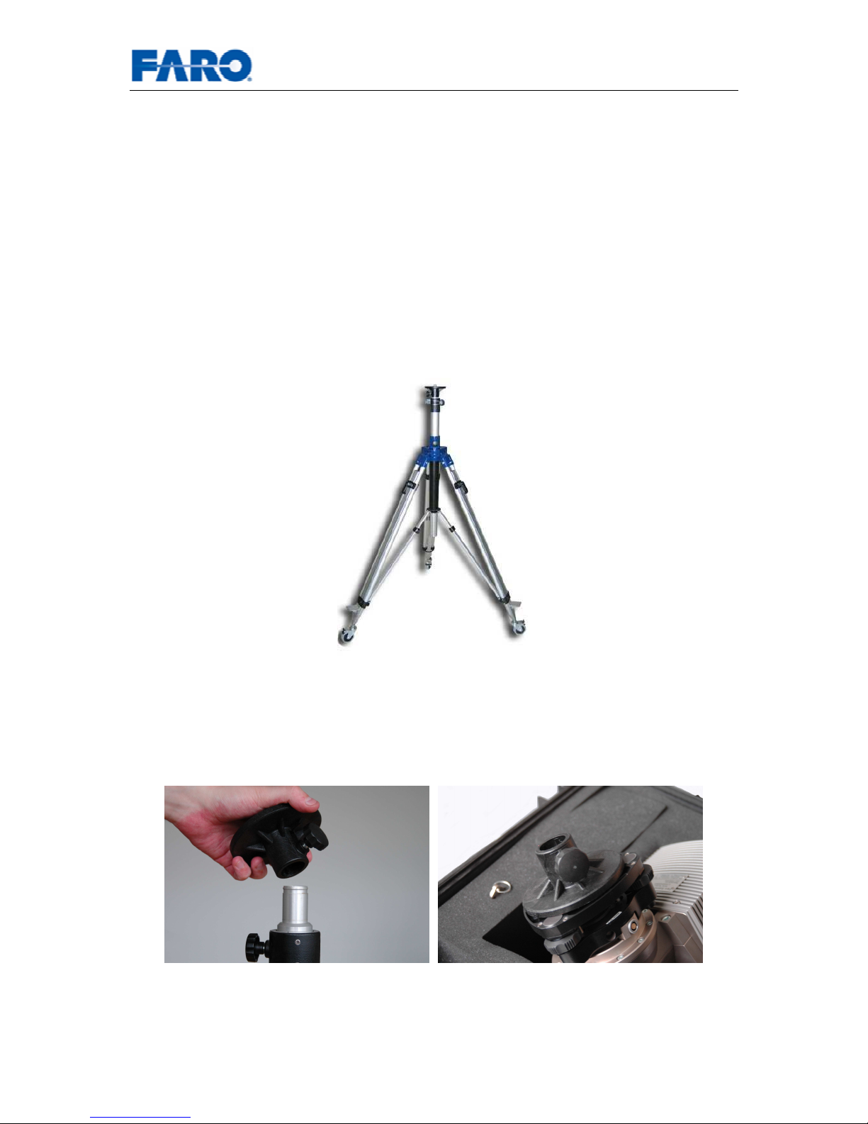
4.1.1 Step 1 - Setting up the tripod
Extend and lock all legs of the tripod. Check that the tripod adjustment arrangements
have been locked and that the legs are of even length. Ensure that the surface is
stable, that the tripod feet are secured and that the tripod is firm in its position.
Fig.4 Tripod
4.1.2 Step 2 – Attaching the Tripod Head
Open the locking screw of the tripod head and remove it from the tripod. Screw the
tripod head to the base of the tribrach. Make sure that it is firmly tightened.
Fig.5 Attaching the tripod head
Page 12
User’s manual FARO Laser Scanner LS 12
© 2007 FARO Scanner Production
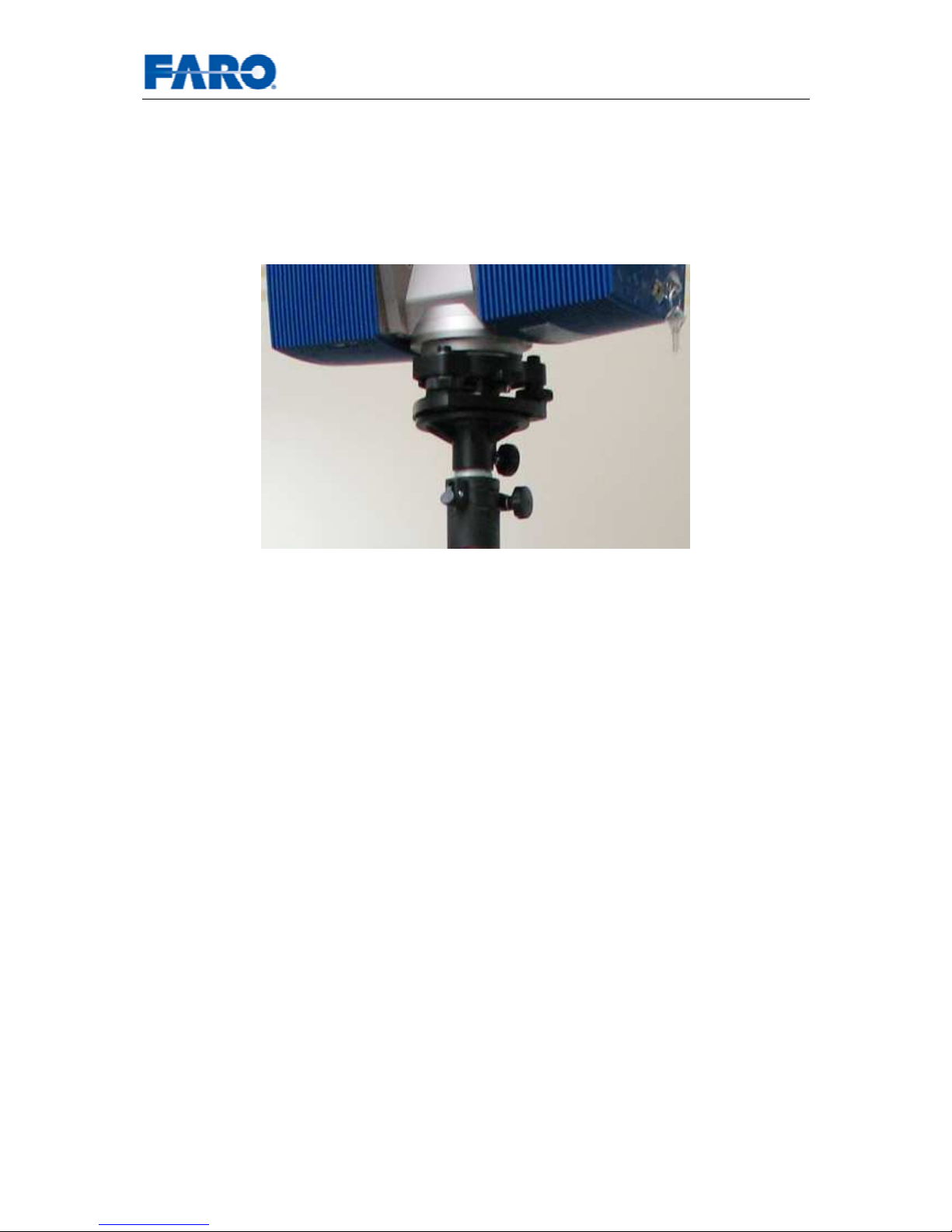
4.1.3 Step 3 – Fixing the FARO Laser Scanner LS
Remove scanner from case, check outer casing for any signs of damage or
distortion. Check mirror for damage due to scratches, cracks, distortion and inspect
for cleanliness.
Place the scanner on the tripod. Once in position lock the scanner into place by using
the tripod’s head locking screw. Test that the scanner is correctly locked in place by
gently attempting to lift it from the tripod.
Fig.6 Scanner on tripod
Page 13
User’s manual FARO Laser Scanner LS 13
© 2007 FARO Scanner Production
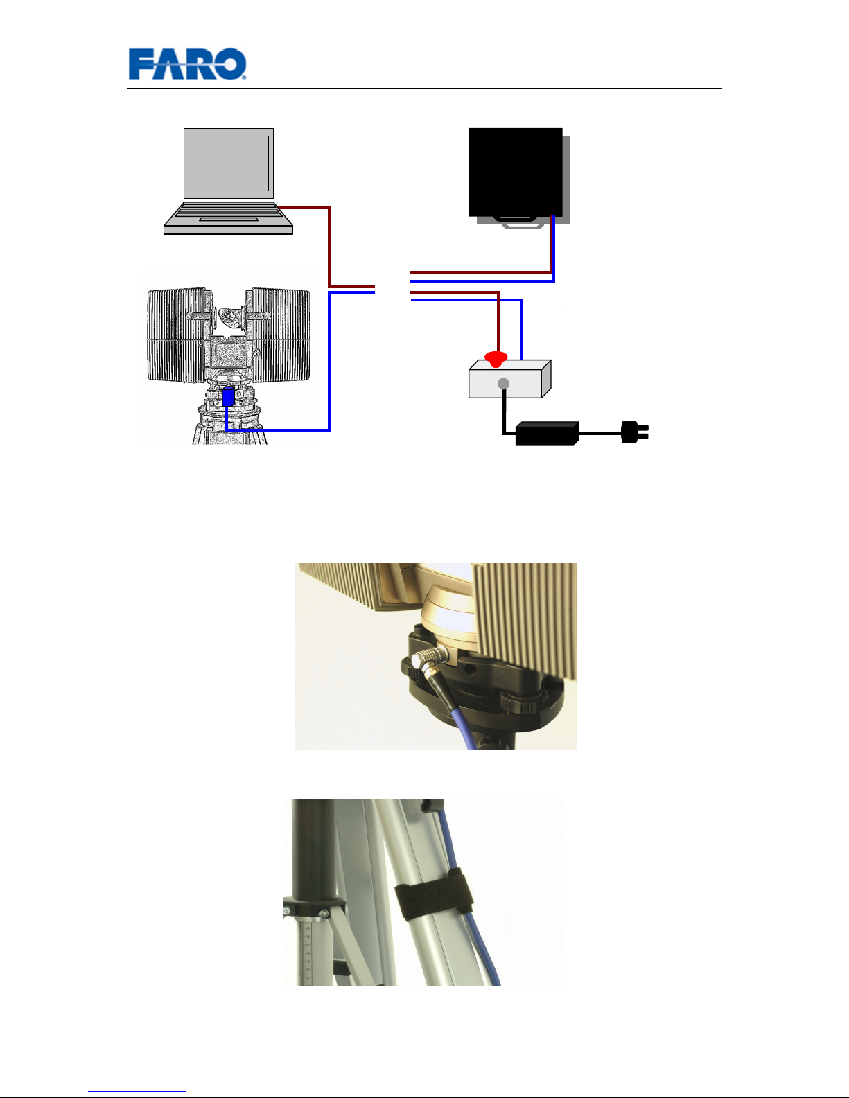
4.1.4 Step 4 – Connecting the FARO Laser Scanner LS
Fig.7 Connection scheme
• Insert the 90° bend connector of the blue data and power cable into the
scanner.
Fig.8 Insert 90° bend connector into scanner
• Attach the blue data and power cable to one of the legs of the tripod.
Fig.9 Blue data and power cable at tripod leg
Connector
box
Power
supply
Data and power cable
or
Ethernet cable
Battery
pack
Page 14

User’s manual FARO Laser Scanner LS 14
© 2007 FARO Scanner Production
Without battery pack
• Ensure that the connector box is switched off (red button pressed).
• Insert the straight connector of the blue data and power cable into the
connector box.
• Insert Ethernet cable into PC port as specified by PC manufacturer and into
the connector box. If the Ethernet connection does not work, an Ethernet
switch and two ordinary Ethernet cables might have to be put between PC and
connector box.
• Check that the power supply unit is switched off and unplugged. Connect
power supply cable to the connector box; connect power cable into an
approved power supply source.
With battery pack
• Ensure that the Battery pack is switched off.
• Insert the straight connector of the blue data and power cable into the battery
pack.
• Insert Ethernet cable into PC port as specified by PC manufacturer and into
the battery pack. If the Ethernet connection does not work, an Ethernet switch
and two ordinary Ethernet cables might have to be put between PC and
battery pack.
Page 15
User’s manual FARO Laser Scanner LS 15
© 2007 FARO Scanner Production
4.1.5 Step 5 - Switching on the scanner
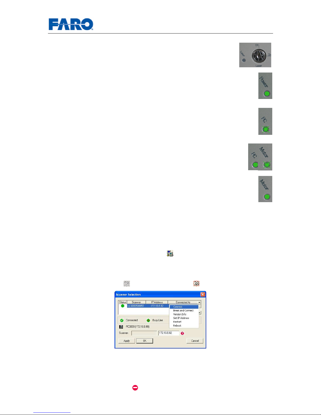
• Check that the laser lock is in Off position.
• Switch on the external operating PC and when the PC is ready, switch
on the power for the scanner by turning the red button on the connector
box or, if you have a battery pack, by using the switch on the battery
pack. The scanner’s Power LED will be on.
• Start the scanner by pushing the On/Off button. This will start the boot
procedure of the internal PC, which will be indicated by the PC LED
turning to red for a moment and then flashing in green.
• When the PC is ready, the PC LED will remain green, while the
Motor LED will be flashing in green till the initial parameter transfer
is finished.
• When the base unit and the mirror unit are ready, the Motor LED will
stop flashing and remain green.
4.2 Installing and using the software
4.2.1 Step 6 – (Software installation)
If FARO Record is not already installed on your PC, insert the CD supplied with the
scanner and follow the installation instructions on the screen.
4.2.2 Step 7 – Establishing an Ethernet connection to the scanner
Run FARO Record and click on the symbol
to select your scanner by a left-click
on the scanner’s name. Open the context menu with a right-click to connect to the
scanner.
The status icon will change to “Connected” after the connection has been established
and the “start scan”-symbol ( ) will become activated ( ).
Fig.10 FARO Record – scanner selection
4.2.2.1 Connection problems
A connection can only established if the scanner and the operating PC have
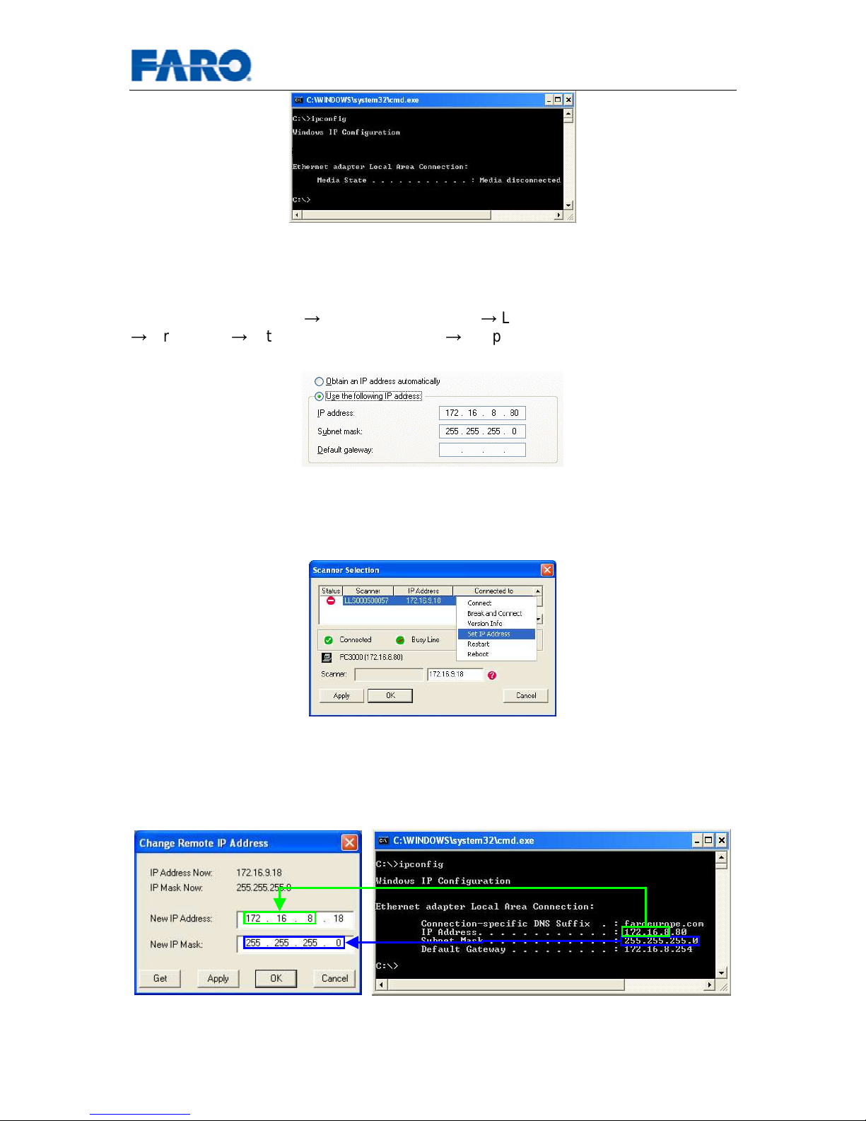
compatible IP addresses and compatible subnet masks. If they don't, this is indicated
by the Net incompatibility icon . You can check the parameters on the operating
PC using the command ipconfig in the windows command prompt.
Page 16
User’s manual FARO Laser Scanner LS 16
© 2007 FARO Scanner Production
Fig.11 Checking IP address with ipconfig
If the operating PC has no valid IP address (like in Fig.11) you might have to assign a
static IP address to the PC. If the operating PC is part of a LAN, ask your system
administration to do this. Else you can configure the operating PC's IP address in
Windows' Control Panel Network Connections Local Network Connection (LAN)
Properties Internet Protocol (TCP/IP) Properties, using the option "Use the
following IP address" and providing a valid IP address and subnet mask.
Fig.12 TCP/IP Properties
If the scanner selection dialog shows a net incompatibility you have to change the IP
address of the scanner remotely. Select the command Set IP address form the
scanner's context menu as shown in Fig.13.
Fig.13 Net incompatibility problems
Change the IP address of the scanner to an address that only differs from the
operating PC's IP address by the last number. The subnet mask of PC and scanner
should be identical. If you sometimes have the scanner connected to your LAN, ask
your system administrator for a yet unused IP address.
Fig.14 Changing the Scanner's IP address
Page 17
User’s manual FARO Laser Scanner LS 17
© 2007 FARO Scanner Production
4.3 Starting a scan
4.3.1 Step 8 – Unlocking the laser
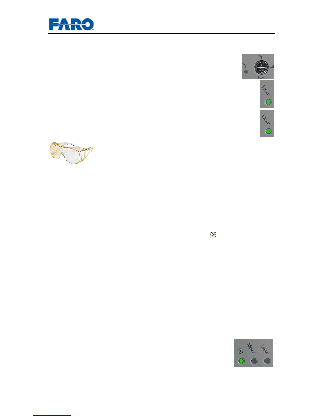
• Insert the key into the lock and turn it to the On position.
• The Laser LED will flash green while exchanging parameters with the
PC unit.
• A red light on the upper part of the scanner and the green Laser LED
will indicate that the laser is unlocked and ready for scanning.
If you are in a distance less than the eye safety distance, wear
your laser safety glasses now and take care that there are no
people in the potentially dangerous area unless they are wearing
laser safety glasses.
Remember that the scanner is turning and the mirror unit is rotating with a high
speed. Ensure that the scanner can move freely and that no objects can touch the
mirror unit.
4.3.2 Step 9 – Scanning
You can start your first scan either by clicking on the symbol
(Start Scan) in FARO
Record, or by pressing the Start button on the scanner. The software might ask for a
name and a place for saving the scan. After this, the scan starts and a progress bar
will be displayed.
In the very first scan after the scanner has been switched on, the scanner starts
turning counterclockwise for a brief moment. Then it stops and starts scanning in
clockwise motion. All consecutive scans are then taken without the initial
counterclockwise motion. On completion of the scan the scanner rotates
counterclockwise back into its initial position.
The result of the scan will be displayed on the screen.
4.3.3 Step 10 – Shutting down the scanner
Lock the laser by turning the key to the Off position. Use the On/Off button on the
scanner (pressing it for at least 5 seconds) or the FARO Record Software to shut
down the scanner.
The PC LED will be flashing green during the shutdown and the
Laser and the Motor LED will be switched off.
After the shutdown is finished, the PC LED will be off and you can
switch off the power supply of the scanner.
Page 18
User’s manual FARO Laser Scanner LS 18
© 2007 FARO Scanner Production
5 Shutdown of the FARO Laser Scanner LS
The FARO Laser Scanner LS has a PC with a hard drive integrated. This internal PC
must be shut down before turning off the power supply. If the power supply is
disconnected or switched off without the scanner being previously shut down, it may
damage the internal PC and might lead to a loss of data.
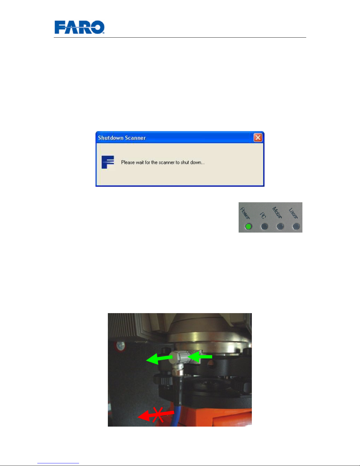
To shut down the FARO Laser Scanner LS, select “Shutdown Scanner” in the
Scanner menu of the FARO Record software. While the scanner is shutting down a
dialog will appear showing the shut down status. DO NOT turn off the power of the
scanner until this dialog has disappeared and the shut down cycle is complete.
Fig.15 FARO Record – shutdown message
Alternatively you can use the button on the scanner to shut
down the scanner. Press the On/Off button on the scanner
for at least 5 seconds. Wait until the shutdown cycle is
complete and the green Motor and PC LEDs are switched
off.
Once the scanner has been completely shut down, the external PC may be shut
down and all power then turned off. When switching off the power, the scanner’s
Power LED will change to red for a short moment and will then be switched off.
Disconnect all cables and secure the equipment in protective cases.
Take care to unplug the bend connector from the scanner by pulling at the
connector only! Do not pull at the combined data and power cable. Else the
connector and the internal PC of the scanner can be damaged!
Fig.16 Unplugging the bend connector
Page 19
User’s manual FARO Laser Scanner LS 19
© 2007 FARO Scanner Production
6 The Software FARO Record
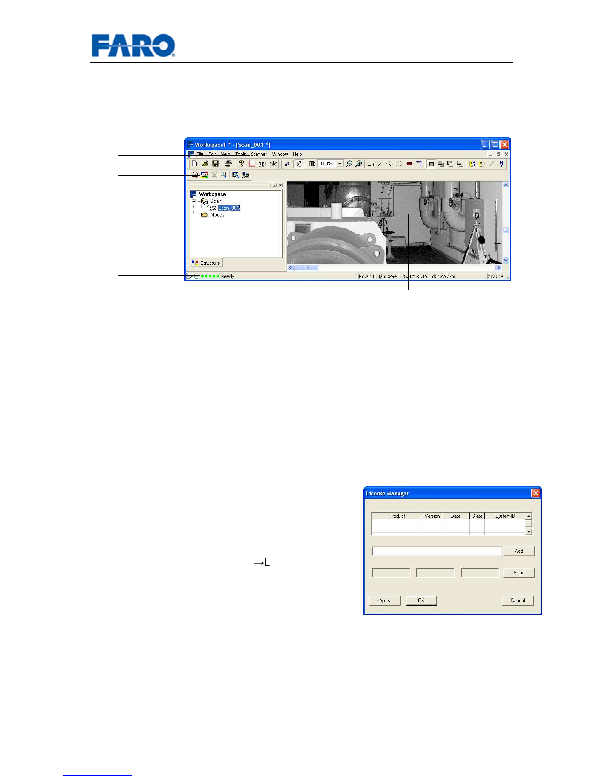
Using FARO Record you can connect to the FARO Laser Scanner LS, configure
parameters, start scans, view the results of your scans and shutdown the scanner.
Fig.17 FARO Record
In this manual only the features which are directly linked to performing a scan will be
addressed. Please refer to the FARO Record user’s manual for the many other
features of the software (like viewing or measuring objects).
6.1 Installation
Insert the Installation CD supplied with the scanner, select the product and follow the
installation instructions on the screen. An installation wizard will guide you during
installation. You must belong to the group of administrators or power users to install
the software.
6.2 License
After the trial period, you need a license to use FARO
Record. If you change your hardware or if you want
to use FARO Record on a different computer, you
will also need a new license, as the license is bound
to a system ID.
With the license manager (HelpLicense Manager)
you can view your licenses, send an e-mail to FARO
requesting a license (Send) and add the licenses that
you have received from FARO (Add). After adding a
license, press OK or Apply.
Scan bar
Scan view
Status bar
Scanner menu
Page 20
User’s manual FARO Laser Scanner LS 20
© 2007 FARO Scanner Production
6.3 The scan bar
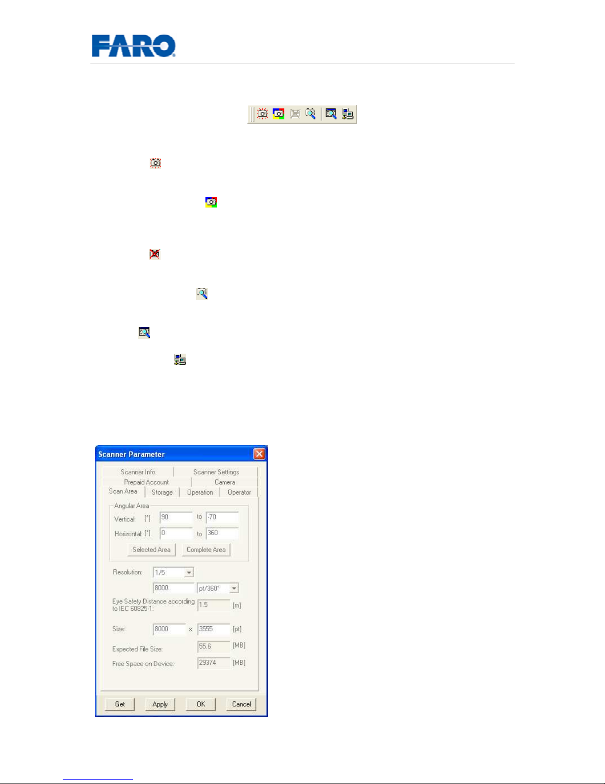
Fig.18 Scan bar
Start Scan : Starts a new scan, if a connection to the scanner has been
established and the scanner is ready.
Start Scan with color : Starts a color scan if the color option is installed. The
scanner will first take an ordinary scan followed by taking a series of color pictures
with the camera. See chapter 7 for details.
Stop Scan
: Stops the scanner during a scan. There might be a short delay till the
scanner stops scanning.
Scanner Parameter : Adjustment of scanner parameters and display of scanner
information.
Settings
: Opens a dialog box for visualization and memory parameters.
Select Scanner : Opens a dialog box for setting the connection with the scanner.
6.3.1 Scanner Parameter
6.3.1.1 General
Get: Updates the values of the scanner
parameter window by getting the actual
values from the scanner.
Apply: Sends the values specified in the
scanner parameter dialog to the scanner.
The scanner checks, if the parameter values
given are applicable. If not, the scanner
changes the parameters according to the
limits of the hardware before setting them. A
notice will be displayed in this case.
OK
: Closes the scanner parameter window.
Uses “Apply” before closing the window if
parameters have been changed.
Cancel: Closes the scanner parameter
window without setting new parameters.
Page 21
User’s manual FARO Laser Scanner LS 21
© 2007 FARO Scanner Production
6.3.1.2 Scan Area
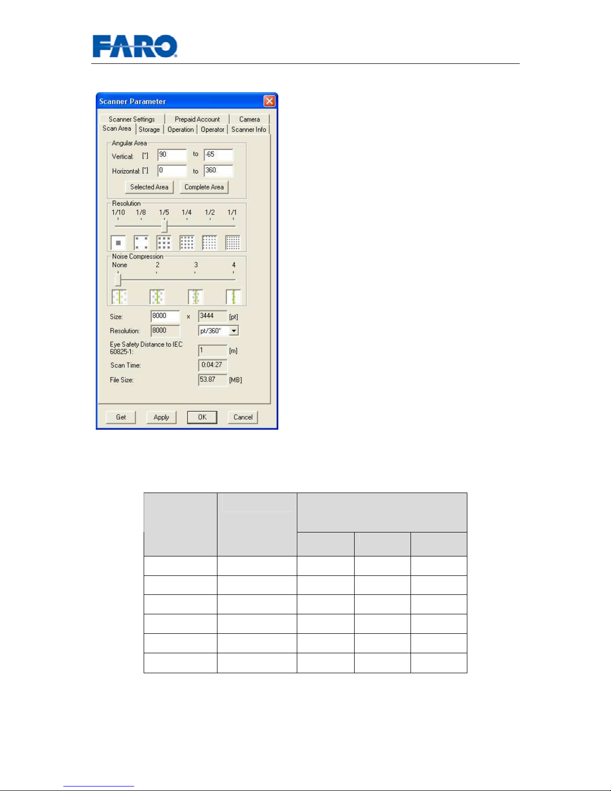
Angular area: The size of the area to be
scanned, both horizontally and vertically.
Scan angle areas may be changed by keying
in the required scan range.
Resolution: The requested resolution. Can
be one of 1/1, 1/2, 1/4, 1/5, 1/8 or 1/10
Noise Compression: The requested
compression ratio. For example, a scan
taken in ¼ resolution with 2x compression
will have the same amount of data as a scan
in 1/8 resolution, but with reduced noise
level.
Size: Shows the size of the scan in points.
Horizontal x Vertical. The vertical size may
only be changed by setting a new resolution
or by changing the scan area angle. It is
recommended to leave the horizontal s
ize
untouched, in order to get a 1:1 points'
ratio.
Dependent on the resolution selected and on the laser power, a minimum distance
has to be observed to prevent eye damage, if the laser beam is observed directly
without laser safety glasses.
Eye safety distance [m]
(nominal ocular hazard distance
NOHD)
Resolution [pt/360°]
420HE 840HE 880HE
1/1 40,000 16.1 4.9 16.1
1/2 20,000 16.1 2.5 16.1
1/4 10,000 9.4 1.3 9.4
1/5 8,000 7.5 1.0 7.5
1/8 5,000 4.7 0.7 4.7
1/10 4,000 3.8 0.5 3.8
Tab.1 Eye safety distance
Page 22
User’s manual FARO Laser Scanner LS 22
© 2007 FARO Scanner Production
6.3.1.3 Storage
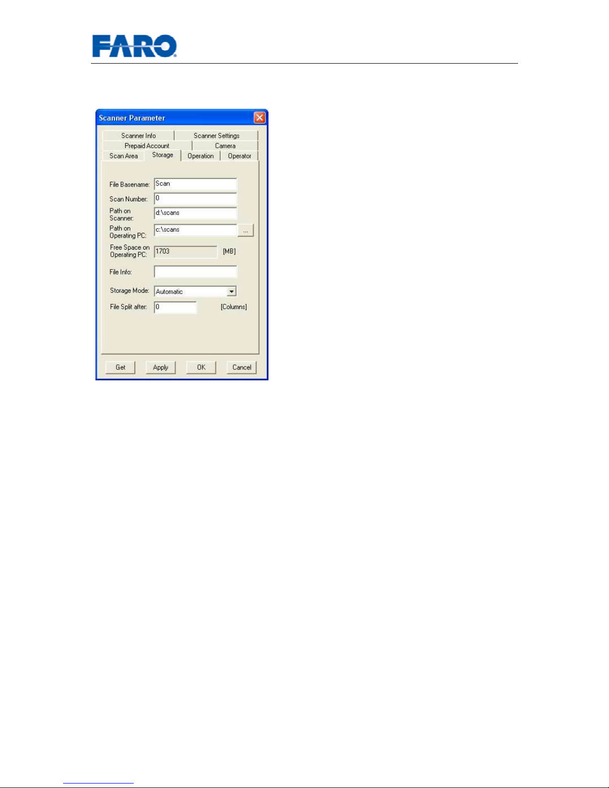
File Basename:
The scan will be saved with
a file name consisting of this base name
followed by the current scan number, e.g.
Scan000.
Scan Number:
Automatically increments
with each successive scan. Can be reset
and may be used
to indicate the number of
scans per scan session.
Path on Scanner:
This is the file path to
store the scans directly on the scanner.
Path on Operating PC:
The file path to
store scans on the Operating PC.
Free Space on Operating PC:
the free disk
space on the Operating PC.
File Info: Additional file info.
Storage Mode:
There are three storage
modes:
• Automatic:
The scan is saved to the
device where the scan was started.
• Scanner:
The scan is saved to “Path
On Scanner”.
• Remote: The scan is saved to “Pat
h
On Operating PC”.
File Split After
: Split the scan files after a
certain amount of columns.
Page 23
User’s manual FARO Laser Scanner LS 23
© 2007 FARO Scanner Production
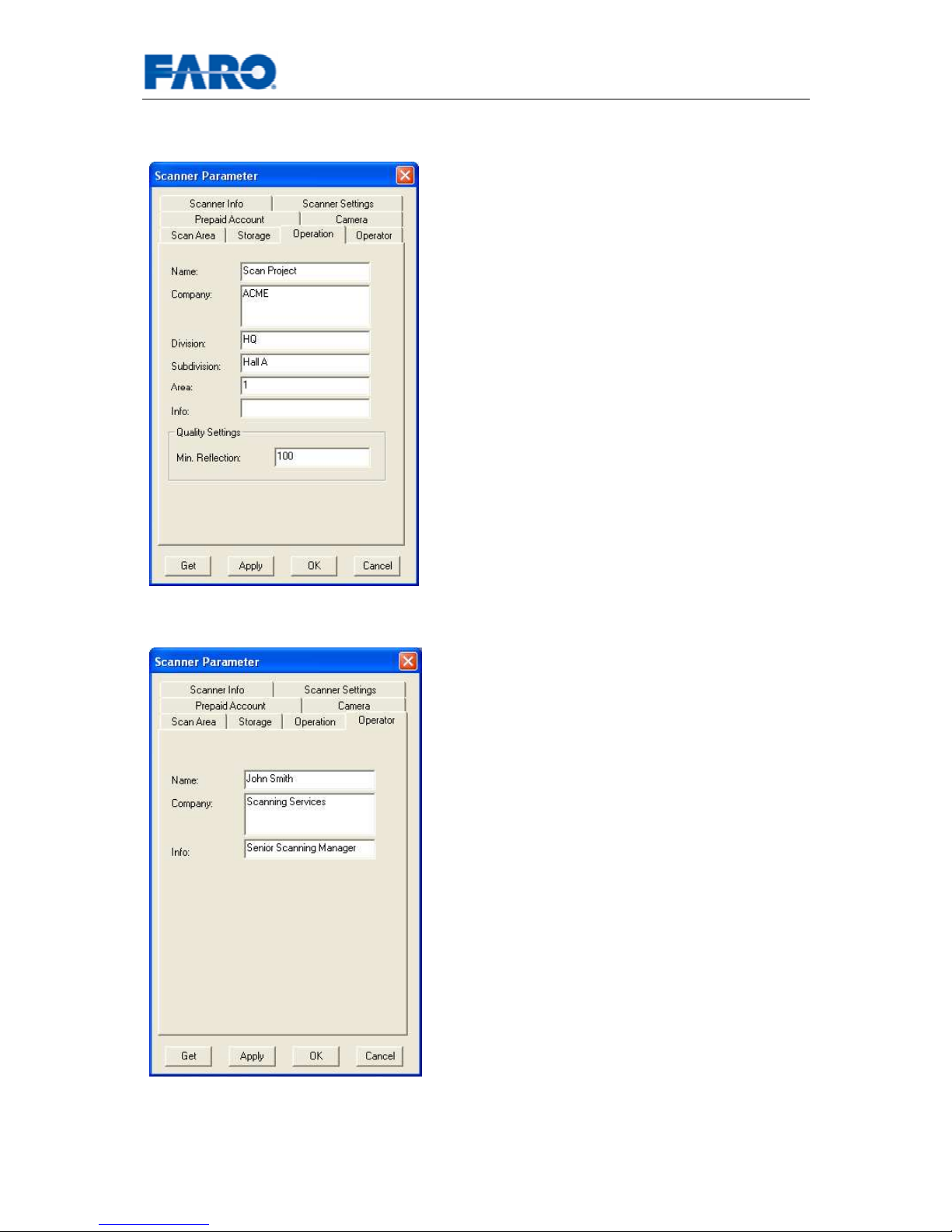
6.3.1.4 Operation
Name: Provides information about the
project name.
Company: Project company’s name.
Division/Subdivision: The
divis
ion/subdivision of the project company
requiring scanning services.
Area: The area within the factory/project to
be scanned.
Info: Any additional information required for
the project, e.g. contact person or areas of
focus in the project.
Min. Reflection: the minimum reflection
value. Only brighter scan points are
recorded.
6.3.1.5 Operator
Name: Contains the name of the scanner
operator.
Company:
The name of the company
providing the scanning service.
Info: Any additional information required by
the service provider. This may be shift
leaders, project managers etc.
Page 24
User’s manual FARO Laser Scanner LS 24
© 2007 FARO Scanner Production
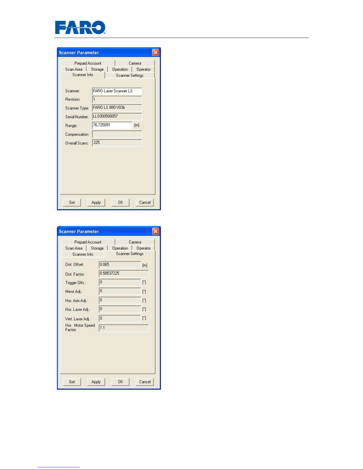
6.3.1.6 Scanner Info
Scanner: Provides the name of the scanner.
Revision:
The revision number of the
scanner.
Scanner Type: The type of scanner.
Serial Number: The scanner's serial
number. This will be individual for each
scanner.
Range: The theoretical unambiguity range of
the scanner. The actual distance range is
dependant on the scanner type.
Compensation: The name of the current
compensation file used.
Overall scans: Shows the number of overall
scans made by this scanner.
6.3.1.7 Scanner Settings
Dist. Offset: Contains the distance offset
value. This value is applied to the distance
measurement to adjust for the scanner’s
physical characteristics.
Dist. Factor: This value is applied to the
distance measurement to adjust for the
environments physical characteristics.
Trigger Offs.: Synchronizes the firing of the
laser with the mirror motor.
Mirror Adj.: An angular measure for the
alignment of the scan half’s.
Hor. Axis Adj.: An angular measure for the
relative sizes of the scan halves.
Hor. Laser Adj.: An angular measure for the
relative sizes of the scan halves.
Vert. Laser Adj.: An angular measure for
the relative sizes of the scan halves.
Hor. Motor Speed Factor: The speed ratio
of the horizontal motor.
Page 25
User’s manual FARO Laser Scanner LS 25
© 2007 FARO Scanner Production
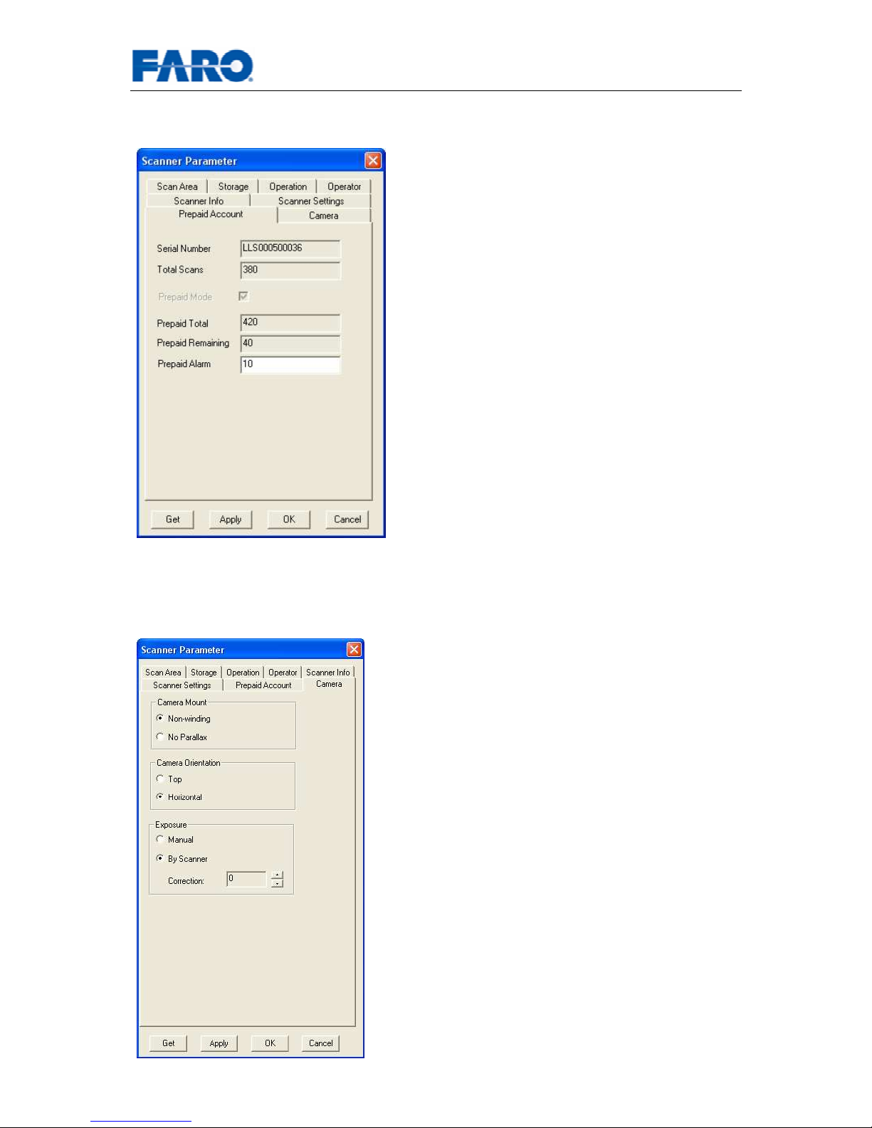
6.3.1.8 Prepaid Account
(Only applicable for prepaid scanners)
Serial Number: The scanner's serial
number. This number is individual for each
scanner.
Total Scans Shows the total number of
scans made by this scanner.
Prepaid Mode: Indicates if the scanner is
running in prepaid mode.
Prepaid Total:
Total number of scans made
by this scanner in prepaid mode.
Prepaid Remaining: Number of remaining
scans available.
Prepaid Alarm:
Allows setting a minimum
number of remaining scans. When this
number is reached, the user will be reminded
to recharge the prepaid account.
Recharging your prepaid account: see
chapter 6.4.
6.3.1.9 Camera
(Only applicable with camera/color option installed)
Camera Mount - selec
t the camera mount
that you have. Non-winding
is the old, fixed
type. No parallax is the new mount with the
sliding mechanism.
Camera Orientation
: select the camera
orientation that you have chosen when
hooking the camera to the camera mount.
Exposure
• Manual
: You can set exposure time,
exposure index, and f-number directly
at the camera. The scanner will not
change your settings.
• By Scanner: The scanner will first
turn around to determine a balanced
exposure setting. Then it will turn
backwards and take all pictures with
that same setting. You can alter the
exposure from the value suggested by
the scanner. A positive correction of
1-2 is appropriate for scans taken in a
dark room with light coming in from
windows.
Page 26
User’s manual FARO Laser Scanner LS 26
© 2007 FARO Scanner Production
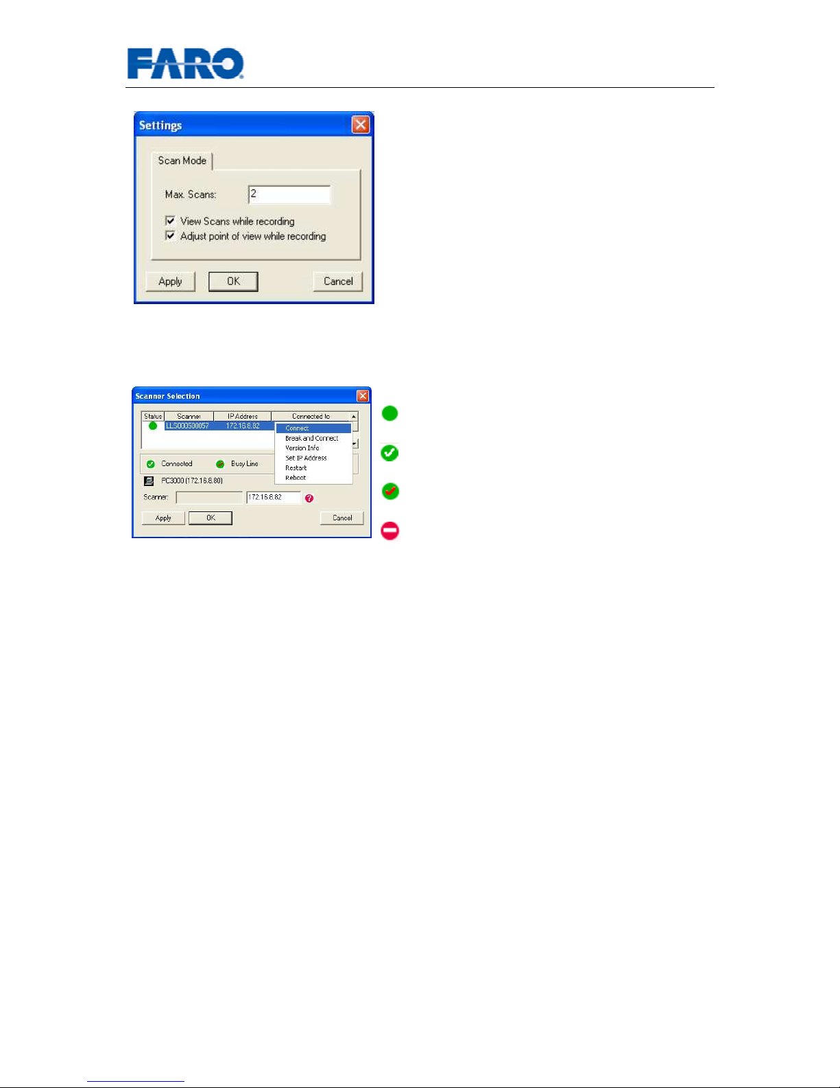
6.3.2 Scanner Settings
Max Scans: Specifies the maximum number of
scans that are kept in the memory of the
operating PC.
View Scans while recording: If checked, the
scan will be displayed online during scanning.
For this option, the operating PC needs
enough main memory to hold a full scan and
must be fast enough to display the scan online.
Adjust point of view while recording: If
checked, the online display of the scan will be
re-centered constantly.
6.3.3 Scanner Selection
Status: There are four possible states
Not Connected: No PC is connected
to the
scanner.
Connected:
The scanner is connected to
the operating PC.
Busy Line: The scanner is connected to a
different PC.
Net Incompatibility: The scanner is
located in a different network. The IP-
address
of the scanner has to be changed in order to be
able to connect to the scanner.
Actions: (right click on the scanner’s name will
open the context menu)
• Connect: Establish a connection with the
scanner.
• Break and Connect: Allows breaking an
established connection between scanner
and a PC different from the operating PC.
After the connection has been ended, a
new connection will be established
between scanner and operating PC.
• Version Info: Displays the version of the
scan server running on the scanner.
• Set IP Address: Allows changing the IP
Address of the scanner.
• Restart: Restarts the scan server
running on the scanner.
• Reboot: Reboots the internal PC of the
scanner.
Page 27
User’s manual FARO Laser Scanner LS 27
© 2007 FARO Scanner Production
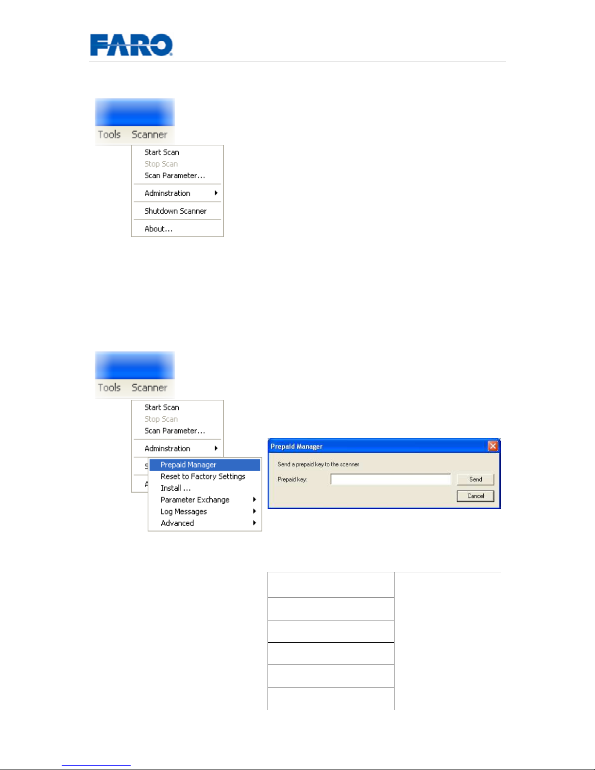
6.4 The Scanner menu
Start Scan: Starts a new scan, if a connection to the
scanner has been established and the scanner is
ready.
Stop Scan: Stops the scanner during a scan. There
might be a short delay till the scanner stops scanning.
Scan Parameter: Opens the Scanner Parameter
dialog.
Administration: Offers functions for administration of
the scanner.
Shutdown Scanner: Shuts down the scanner (see
chapter 5).
About...: Displays the version of the FARO Scanner
Control.
Recharging your prepaid account.
Prepaid Manager: Opens the dialog box to
send a prepaid key to the scanner. If the key is
valid, and the scanner is a prepaid scanner, the
number of remaining scans will be incremented.
You can check the number of remaining scans
in the Scanner Parameter – Prepaid Account
information (see chapter 6.3.1.8)
Reset to Factory
Settings
Install ...
Inclinometer…
Parameter Exchange
Log Messages
Advanced
These functions are
for service
purposes only and
implement basic
diagnosis and
service procedures.
Consult the
customer service
before using these
functions.
Page 28
User’s manual FARO Laser Scanner LS 28
© 2007 FARO Scanner Production
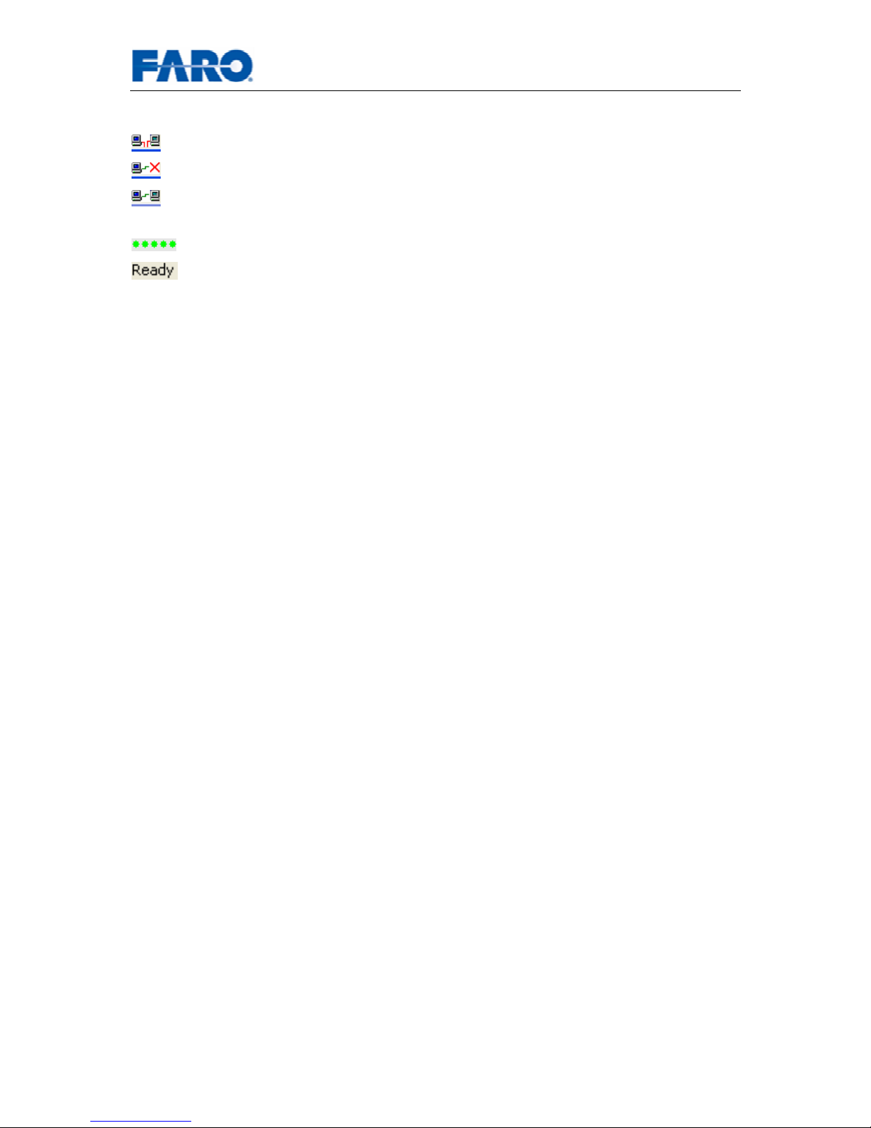
6.5 Status bar
The operating PC is not connected to a scanner.
A connection is being established or is currently interrupted.
A connection between operating PC and scanner is established. The
connection can be ended by double-clicking on this icon.
The scanner is ready for a scan.
Status messages
Page 29
User’s manual FARO Laser Scanner LS 29
© 2007 FARO Scanner Production
7 Color Option
With the color option, you can take scans in which each scan point has not only its
3D information, but also color value associated with it.
Fig.19 Scans with color
This is done by a combining the ordinary scanner with a digital camera. The digital
camera is hooked onto the scanner and controlled by the scanner software.
When a color scan is taken, the scanner first performs a normal scan. Then it takes a
turn to determine a balanced exposure setting. Finally in a third turn the digital
pictures are taken.
7.1 Initial Setup of the camera
Before you can use the digital camera, you have to ready the camera. Have a look at
the Nikon D200 quick start guide and perform the following steps:
• Charge the battery.
• Insert the battery.
• Choose a language and set the clock.
• Attach the lens.
• Insert the memory card.
• Format the memory card.
Be sure to do this at least 2 hours before you want to use the camera, as charging an
exhausted battery takes some time.
7.2 Setup before scanning
The first time you want to use the camera for scanning, you have to change certain
settings of the camera. It is recommended to check these settings each time before
you use the camera again.
Please have a look at the Nikon D200 Quick Start Guide to see how to perform the
following steps:
Page 30
User’s manual FARO Laser Scanner LS 30
© 2007 FARO Scanner Production
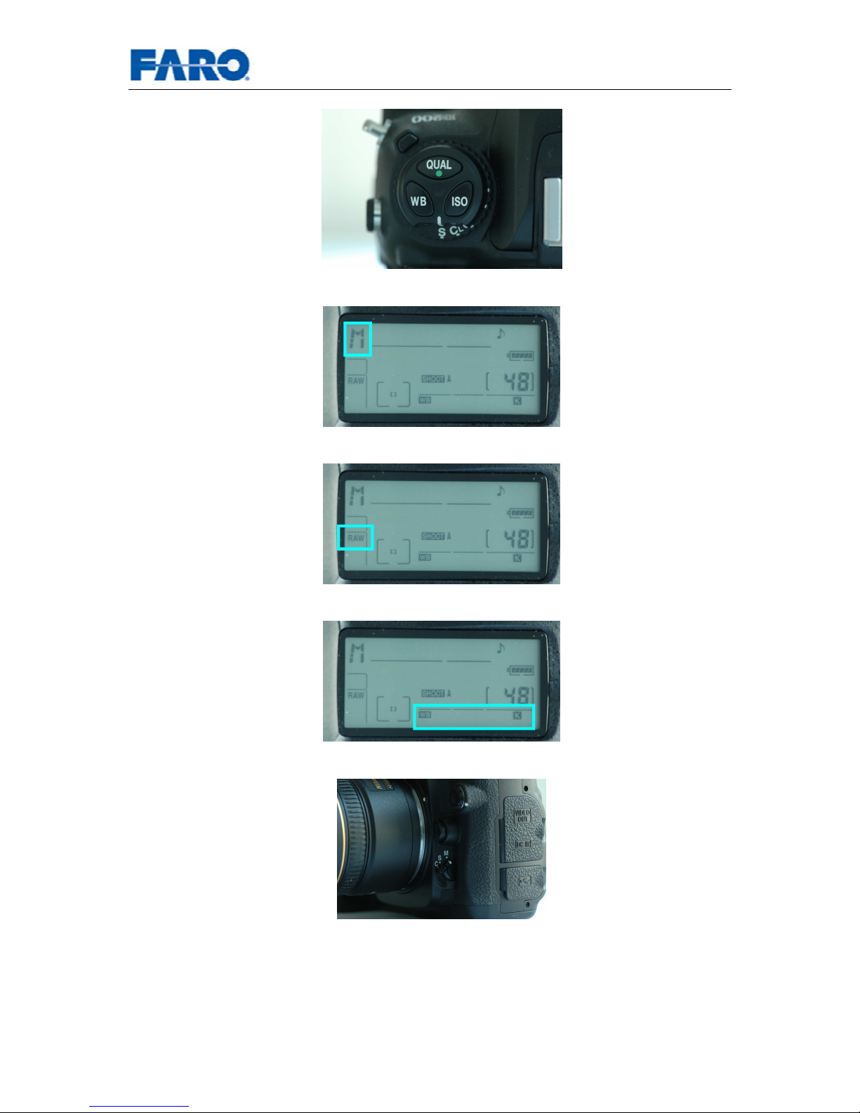
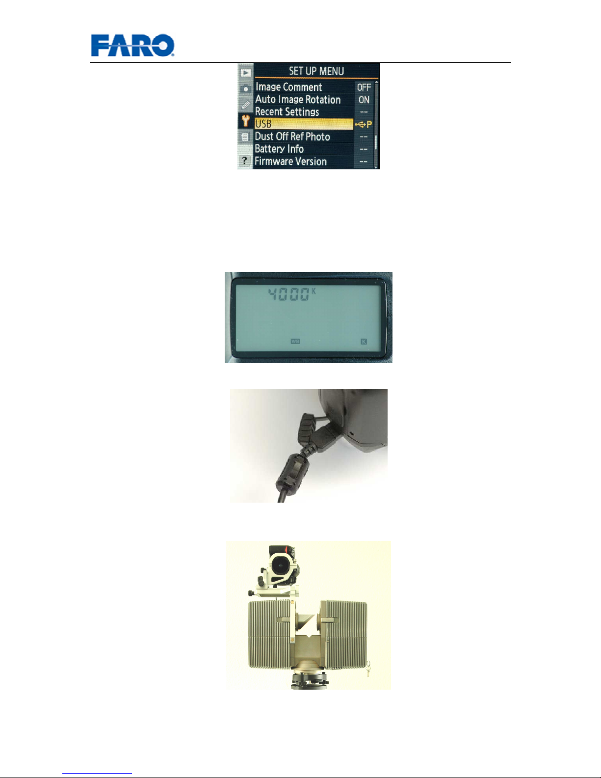
• Set the shooting mode to S
• Select M mode
• Set image quality to RAW
• Set white balancing to K
• Rotate the focus-mode selector to M
Have a look at The Nikon Guide to Digital Photography with the D200 to perform the
following:
• Set the USB option to PTP.
Page 31
User’s manual FARO Laser Scanner LS 31
© 2007 FARO Scanner Production
The following steps have to be done each time before scanning:
• Select an appropriate white balance temperature. Auto white balance is not
recommended, as your panoramic environment probably contains a lot of
different light sources which would cause a different white balance on each
picture.
Make some test images to check the white balance setting.
• Turn the camera off and connect the USB cable to the camera.
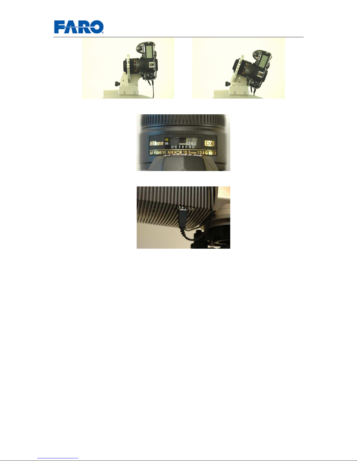
Now prepare the scanner and hook up the camera:
• Put the camera mount on the mirror module of the scanner.
• Either use horizontal orientation of the camera or top orientation.
Page 32
User’s manual FARO Laser Scanner LS 32
© 2007 FARO Scanner Production
• Adjust the focus manually to ∞ using the lens focusing ring.
• Connect the USB cable to the scanner.
• Turn the camera on.
7.3 Scanning with color
• Start FARO Record and connect to the scanner as usual.
• Open the camera tab of the scanner parameter dialog and adjust the camera
parameters according to chapter 6.3.1.9.
Make sure that the correct camera mount and camera orientation is selected.
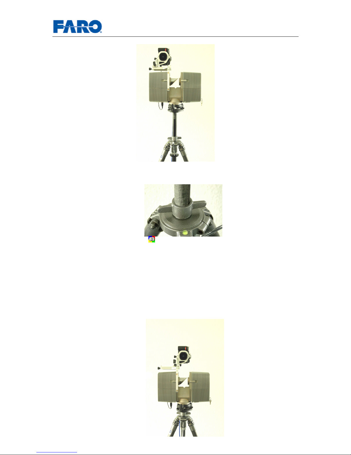
• If you are using the new non-parallax camera mount with the sliding
mechanism, make sure that the camera is now in its parking position over the
mirror module and the scanner is wound up.
Page 33
User’s manual FARO Laser Scanner LS 33
© 2007 FARO Scanner Production
• The gear column may have some rotational degree of freedom. When
tightening the fastener, please make sure that the gear column is at one of its
end positions within this freedom.
• Start scanning by pressing
The scanner will now first take an ordinary scan and will turn 180°. Then it will
continue to turn to 360° and determine additional exposure settings. At the end
of the full turn, it will calculate a balanced exposure setting.
• If you are using the new non-parallax camera mount with the sliding
mechanism, you are now asked to move the camera into its operating position
over the mirror itself, and to wind down the scanner.
If you are using the new FARO carbon fibre tripod set as shown in the pictures
wind down the scanner the whole distance of the gear column (20
centimeters). If you are using other tripods wind down the scanner for exactly
20 centimeters.
Page 34
User’s manual FARO Laser Scanner LS 34
© 2007 FARO Scanner Production
Please make sure that the gear column is at the same end position in its
rotational freedom as before.
• The scanner will now turn backwards and will stop several times to take a
picture on each stop.
• The pictures are automatically transferred to the controlling computer and put
into the scan file.
7.4 Applying the pictures to the scan
The scan points aren’t colorized automatically after the scan has been taken. This
process has to be started manually.
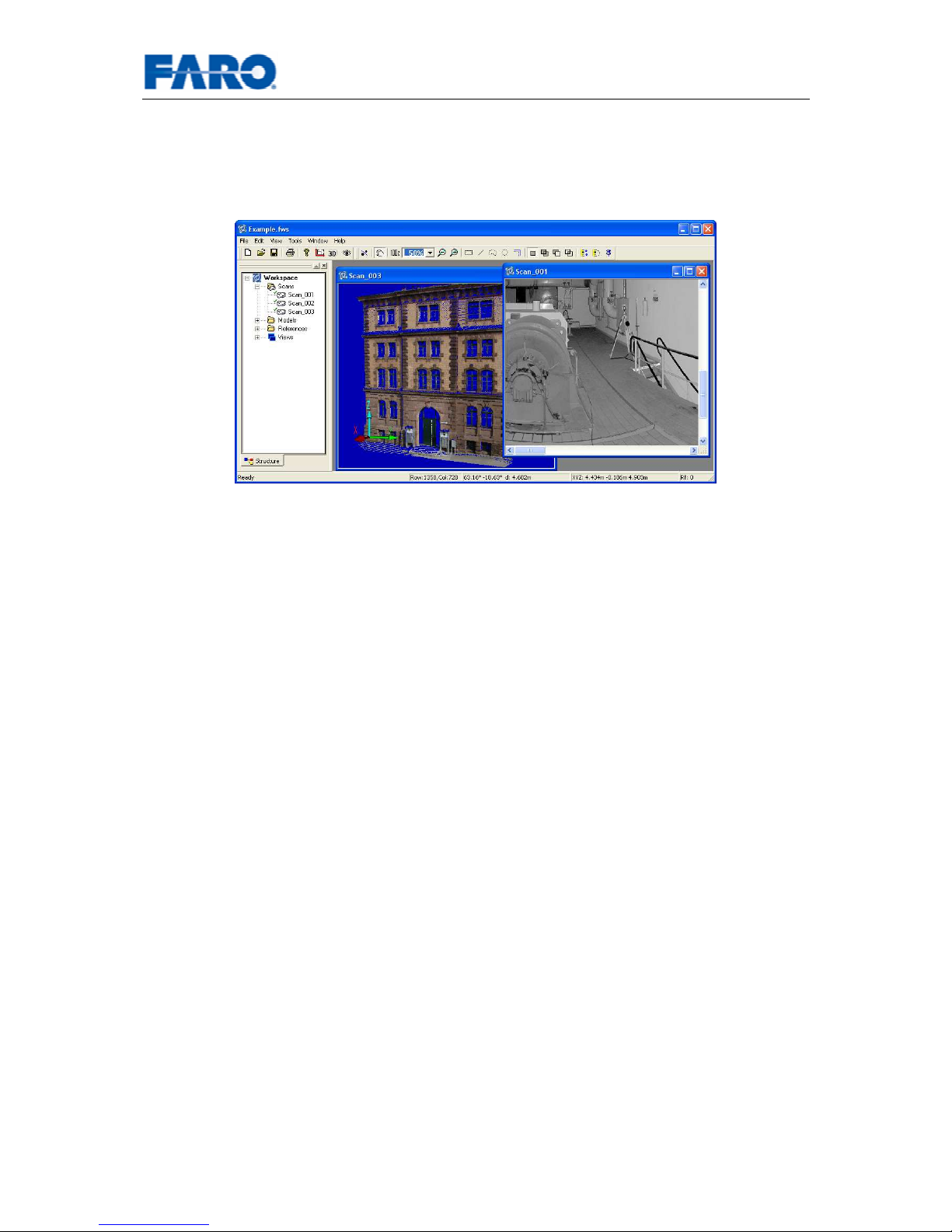
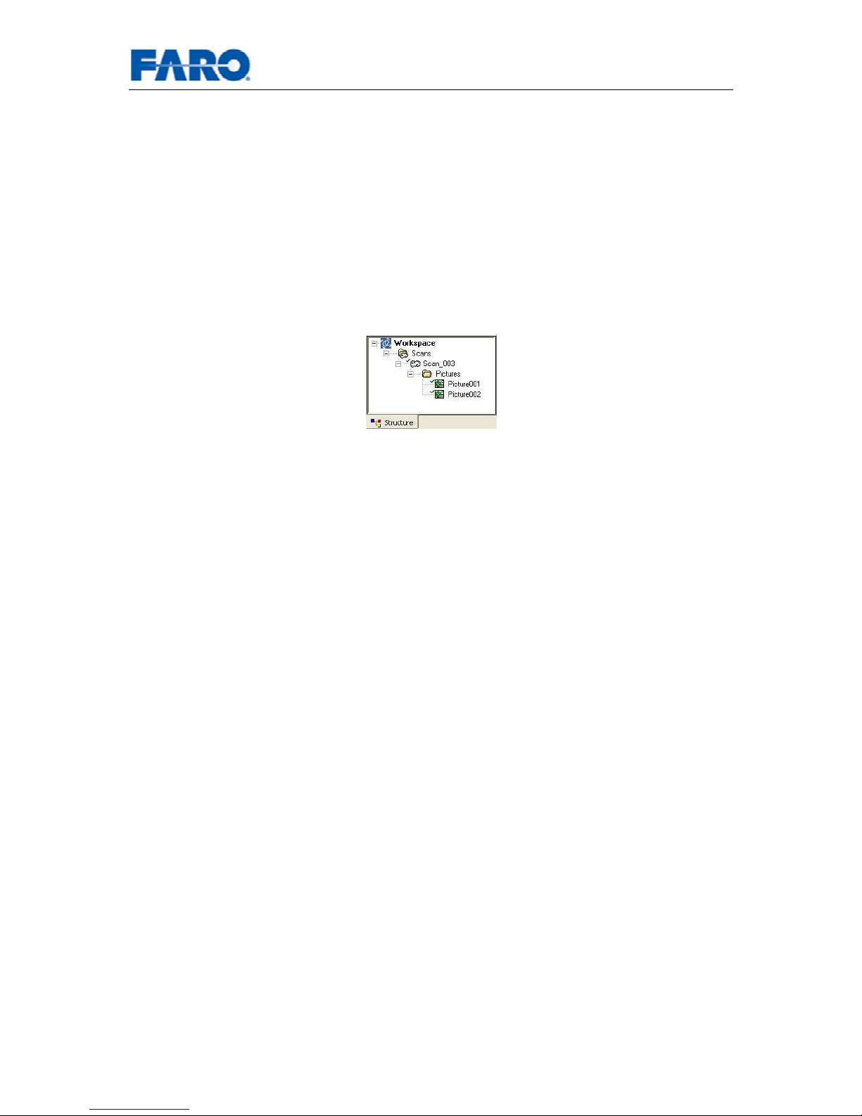
The scanner based pictures are stored within the scan and can be seen in the
structure view.
Fig.20 Scan with pictures
Select the command Apply Pictures in the context menu of the scan. This will first
load the scan and all its pictures. Then it will remove any distortions from the
pictures. Finally it will add the color information to the scan points. Please don’t forget
to check the setting of Save modified scan points in the options and to save the scan
afterwards, this is not done automatically.
If you want to treat every scan in your scan folder that way, you can select the
command Apply Pictures in the context menu of the scan folder. In this case, the
scans are saved automatically afterwards if you have the correct setting of Save
modified scan points in the options.
Page 35
User’s manual FARO Laser Scanner LS 35
© 2007 FARO Scanner Production
8 Using FARO Record Mobile with a PDA
FARO Record mobile offers a web interface to control the scanner. In combination
with WLAN and a PDA, this is a very comfortable way to operate the Laser Scanner
LS. Please note that old scanners need a special software upgrade for FARO Record
mobile.
As the scanner will now offer to different connection types (LAN and WLAN), a
conflict may arise when both a laptop and a PDA are used at the time. In this case,
the scanner is not operable with the PDA.
Please note: Although any web browser can be used on the PDA, some of them
show problems with image manipulation like zooming. It is recommended to use
Opera Mobile (
http://www.opera.com/) for smooth operation.
8.1 Setting up the WLAN connection
8.1.1 FARO LaserScanner LS
Attention: Use the blue data and power cable with the bend connector!
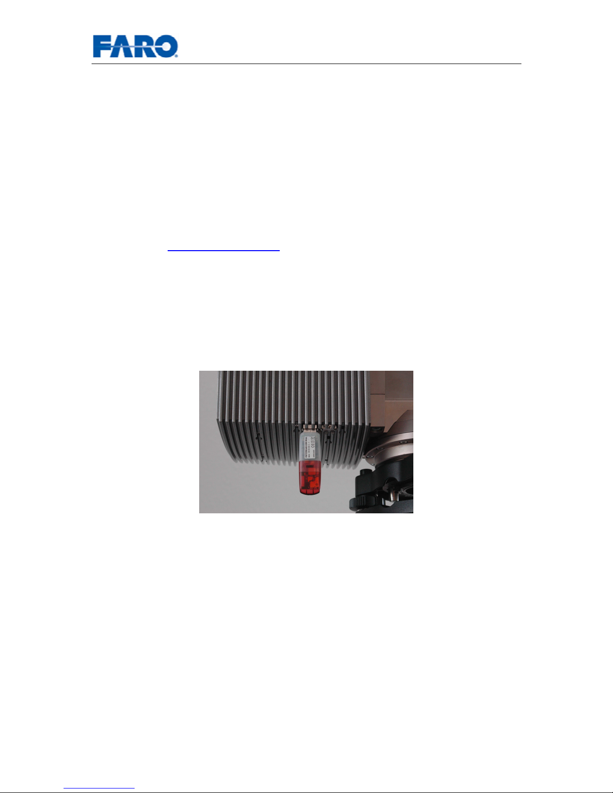
Plug the Fritz!WLAN USB stick into one of the USB ports of the scanner. Please note
that you can only use the Fritz!WLAN USB stick to establish a WLAN connection to
the scanner.
Fig.21 WLAN Stick in the USB port
The WLAN of the scanner is automatically configured to be in Adhoc mode with WEP
encryption. The IP address and subnet mask of the WLAN connection are derived
from the scanner’s ordinary LAN connection. In order to get the actual WLAN
settings, you should use your laptop and the ordinary LAN connection. Start your
favorite web browser on your laptop and connect to FARO Record mobile on the
scanner by entering the LAN IP address. Make sure that no FARO Scene is currently
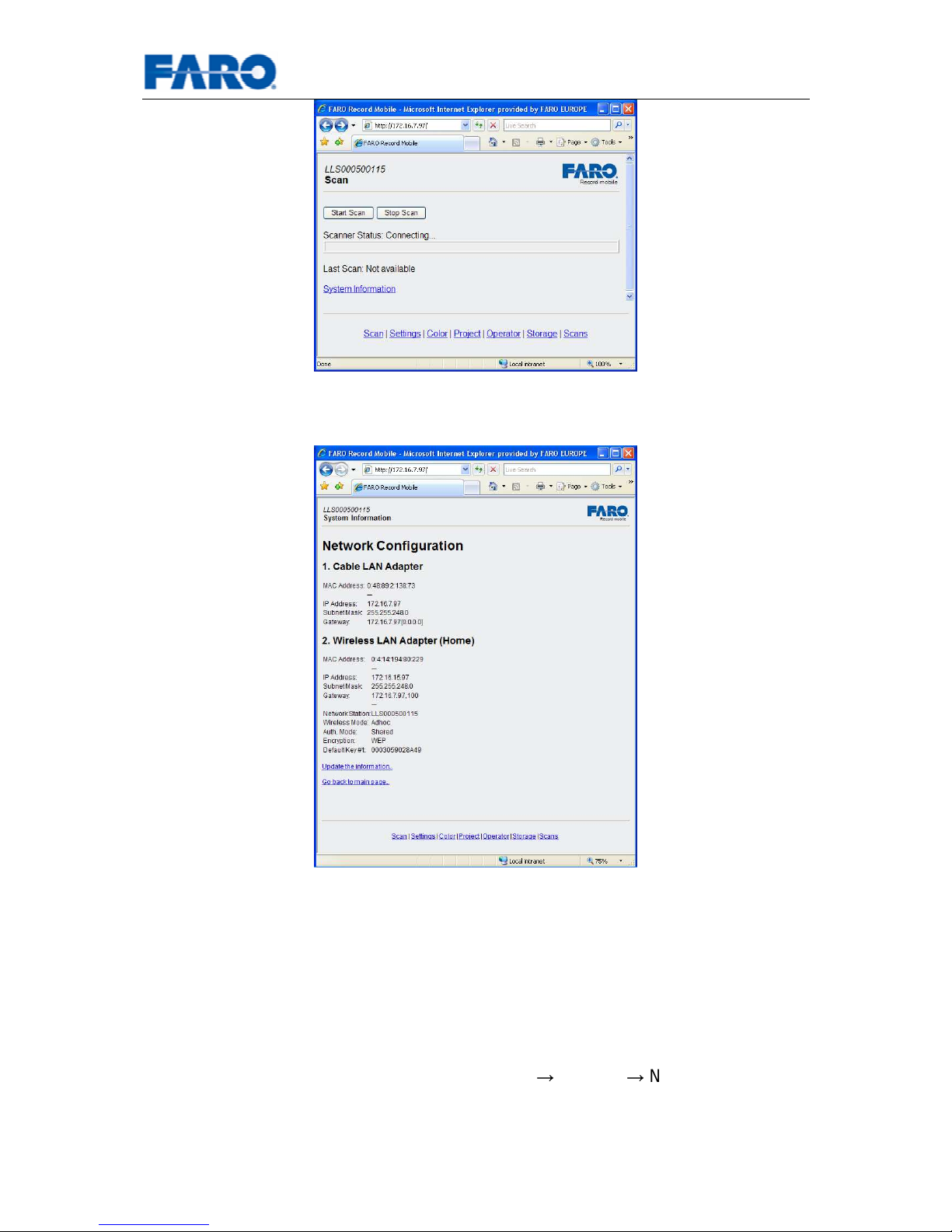
connected to the scanner. You should now see the start page of FARO Record
mobile.
Page 36
User’s manual FARO Laser Scanner LS 36
© 2007 FARO Scanner Production
Fig.22 Start page of FARO Record mobile
Follow the link System Information, and you will see the WLAN connection settings.
Fig.23 System information of the scanner’s networks
You’ll need the WLAN IP address, the WLAN subnet mask, and the WEP key when
setting up your PDA.
8.1.2 PDA
Please consult the user manual of your PDA on how to setup its WLAN connection.
In general, in order to configure the WLAN connection, you have to open the
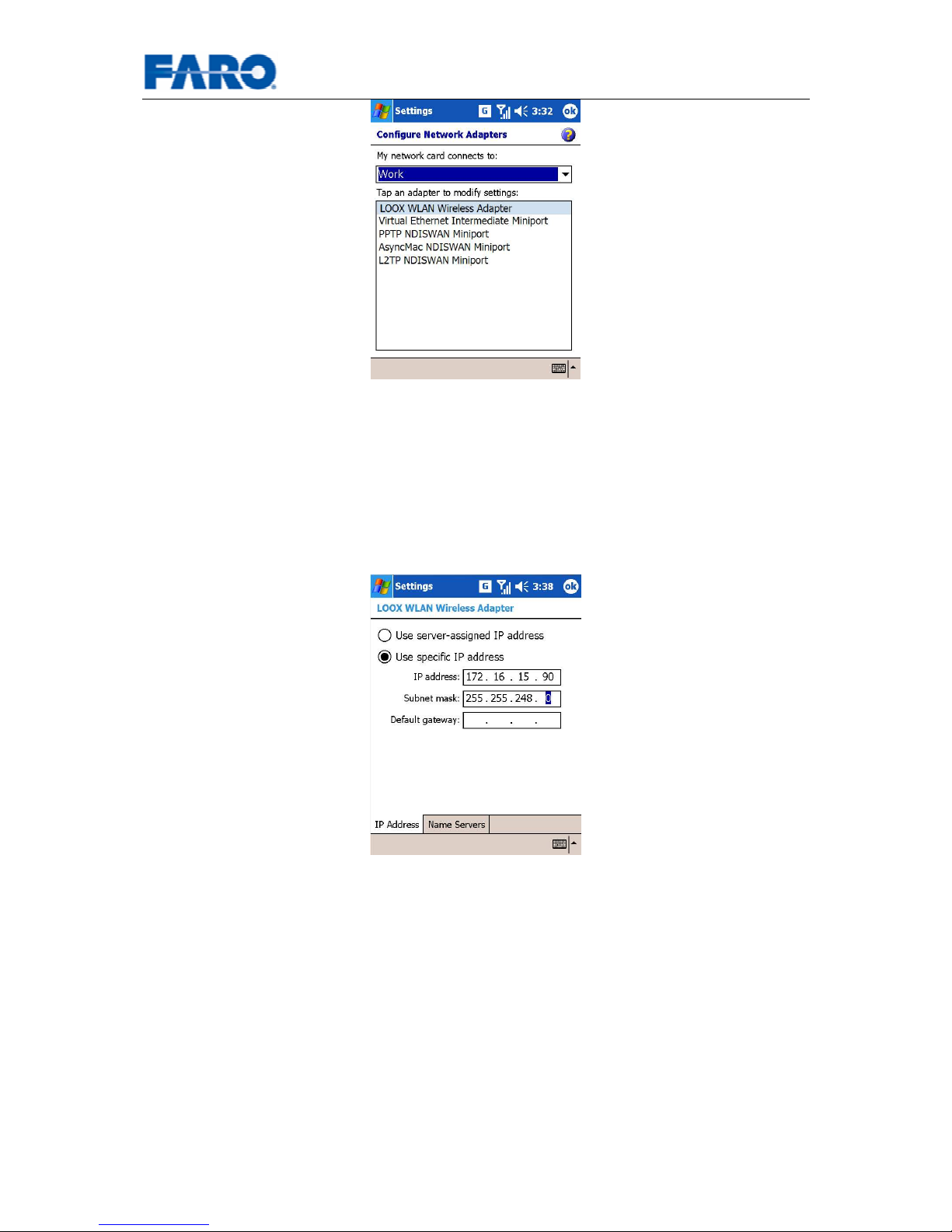
configuration dialog of the network adapters: Start Settings Network Cards
Page 37
User’s manual FARO Laser Scanner LS 37
© 2007 FARO Scanner Production
Fig.24 Select WLAN adapter
Select the WLAN adapter, and enter a WLAN IP address and WLAN subnet mask.
The WLAN IP address should be compatible with the one of the scanner (see
chapter 8.1.1). If you like, you can take the WLAN IP address of the scanner and
simply change the last number. For example, if the scanner has 172.16.15.97, you
can enter 172.16.15.90 here.
The WLAN subnet mask should be the same as the one of the Laser Scanner LS
Fig.25 WLAN IP address
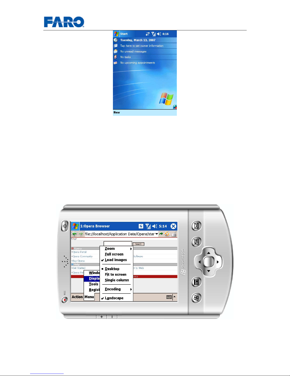
On some PDA’s, you may have to explicitly switch on the WLAN connection (for
example by clicking on the earth globe as seen in the lower right corner in the
following figure). In addition, some PDA’s may require a reboot after the WLAN
address has been changed. Most often, this reboot is performed by pressing a tiny
button with a pencil.
Page 38
User’s manual FARO Laser Scanner LS 38
© 2007 FARO Scanner Production
Fig.26 Switch WLAN connection on
It should then show you the available network of the scanner, to which you can
connect to. You will then be asked for the security key, which you have retrieved
before (see chapter 8.1.1).
8.2 Setting up Opera
When using Opera it is recommended to change some default settings of Opera as
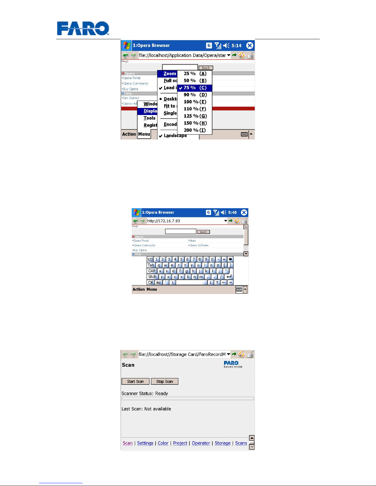
described below. Open Opera on your PDA, select Menu, then Display, and activate
Desktop. It is also recommended to change the orientation to the Landscape. Please
also notice the option Full Screen which you can activate to maximize the usable
screen area for FARO Record mobile. To return from Full Screen hold the pen down
on the screen until a context menu appears and click on Full Screen again.
Fig.27 Recommended display settings for Opera
The built-in zoom function of Opera is also very useful. Setting it to 75% will ensure
that all web pages will fit on the small PDA.
Page 39
User’s manual FARO Laser Scanner LS 39
© 2007 FARO Scanner Production
Fig.28 Recommended zoom settings
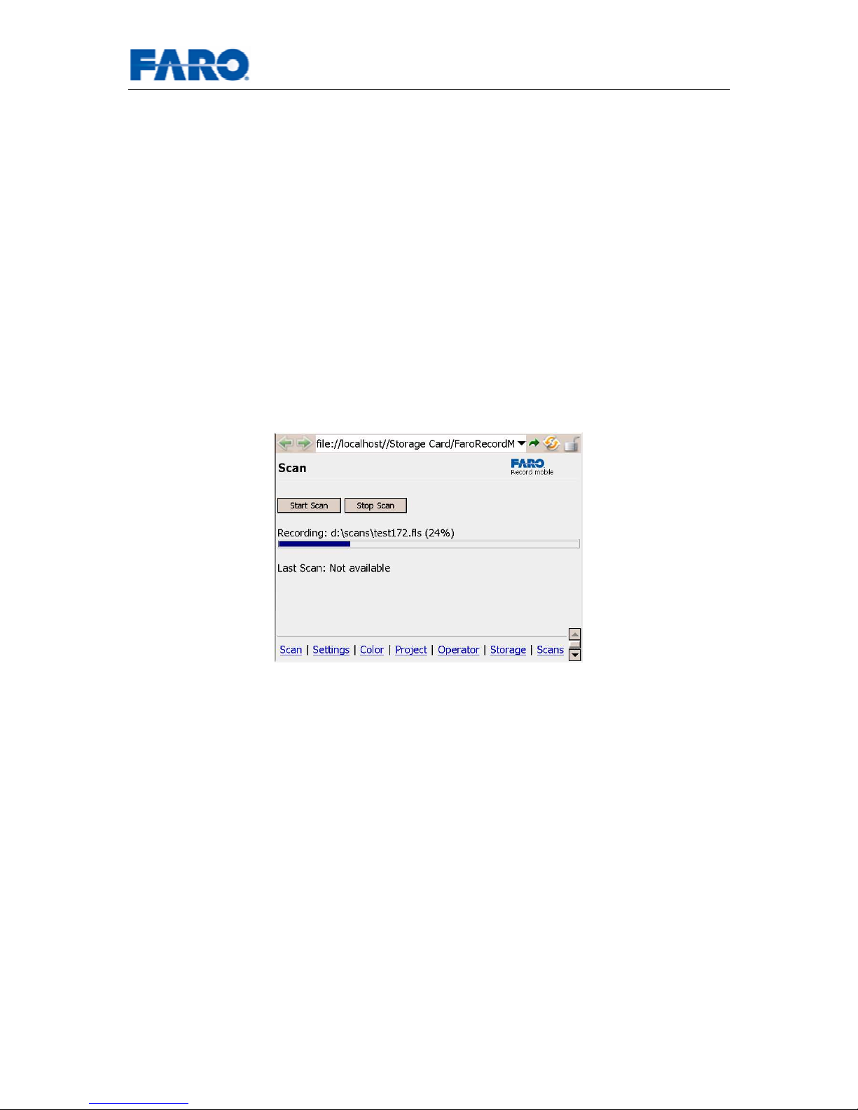
8.3 Connecting to the Scanner
In order to connect to the scanner type the scanner’s WLAN IP address into the
address bar.
Fig.29 Connecting to a scanner by its WLAN IP address
If you set up WLAN connection properly and the scanner has FARO Record mobile
installed, you should now see the Scan page of FARO Record mobile (Please notice
that the Full Screen mode was turned on as described in the beginning of this
chapter).
Fig.30 FAR Record mobile Scan page
Page 40
User’s manual FARO Laser Scanner LS 40
© 2007 FARO Scanner Production
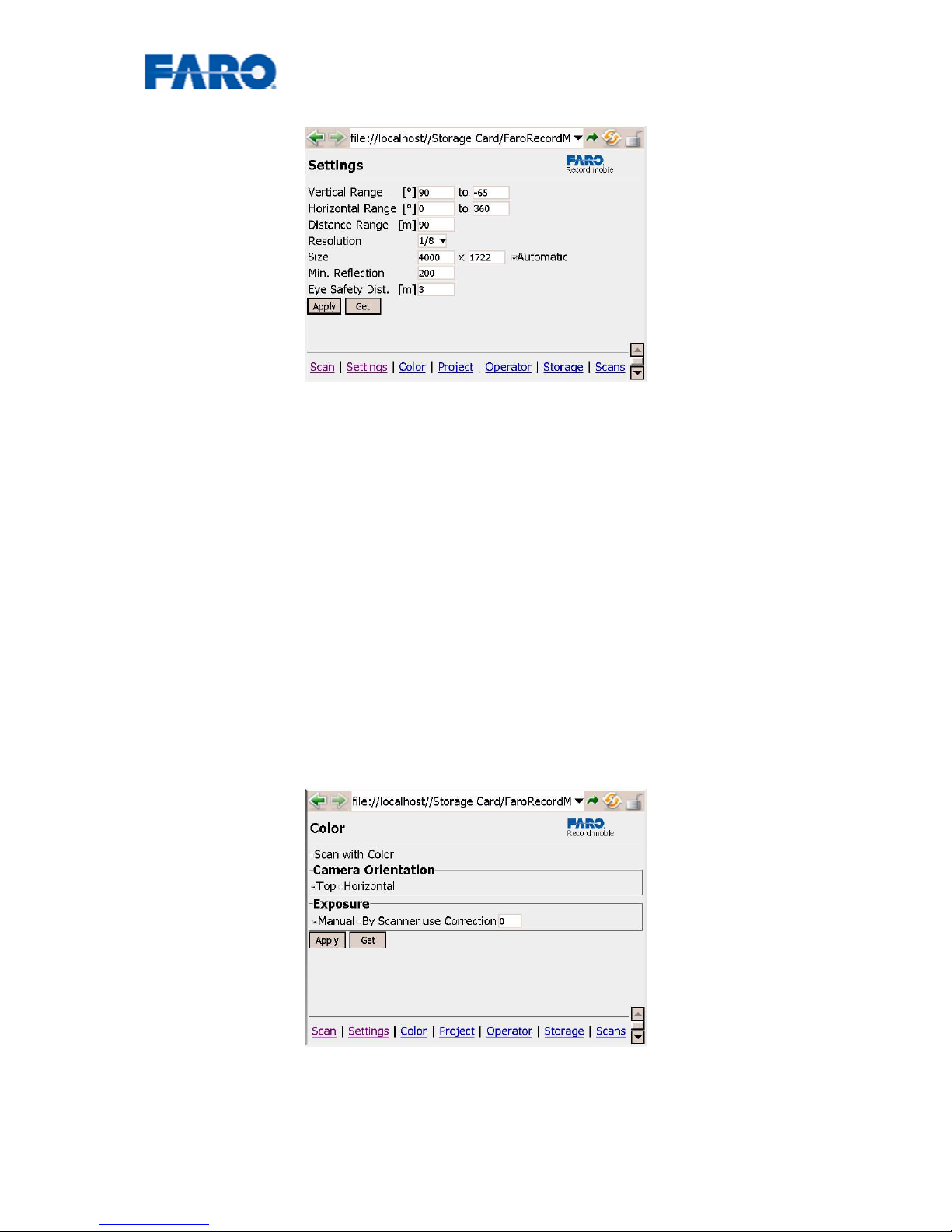
The Scan page is the default page which is displayed if you connect to the scanner.
At the bottom you see the navigating area with links to all FARO Record mobile
pages: Scan, Settings, Color, Project, Operator, Storage, Scans. These pages are
described in the following sections
8.4 FARO Record Mobile Pages Description
Typically you want to check various scanner parameters before scanning, so in the
next sections all the pages are described in their displayed order.
8.4.1 Scan Page
On the Scan page you can actually start the scanning process, stop it, observe
scanning progress and see status messages. If the scanner is ready to scan its
status is Ready. You can start scanning by pressing the Start Scan button. While
scanning you can observe the scan progress bar.
Fig.31 Observing scan progress
When the scan is completed the status of the scanner goes back to Ready and the
entry Last Scan will show a link to the scan image. If you follow this link you should
see the image of the just recorded scan. For further details about viewing scans
consult the chapter 8.5.
You can stop scanning at any time by pressing the Stop Scan button.
Page 41
User’s manual FARO Laser Scanner LS 41
© 2007 FARO Scanner Production
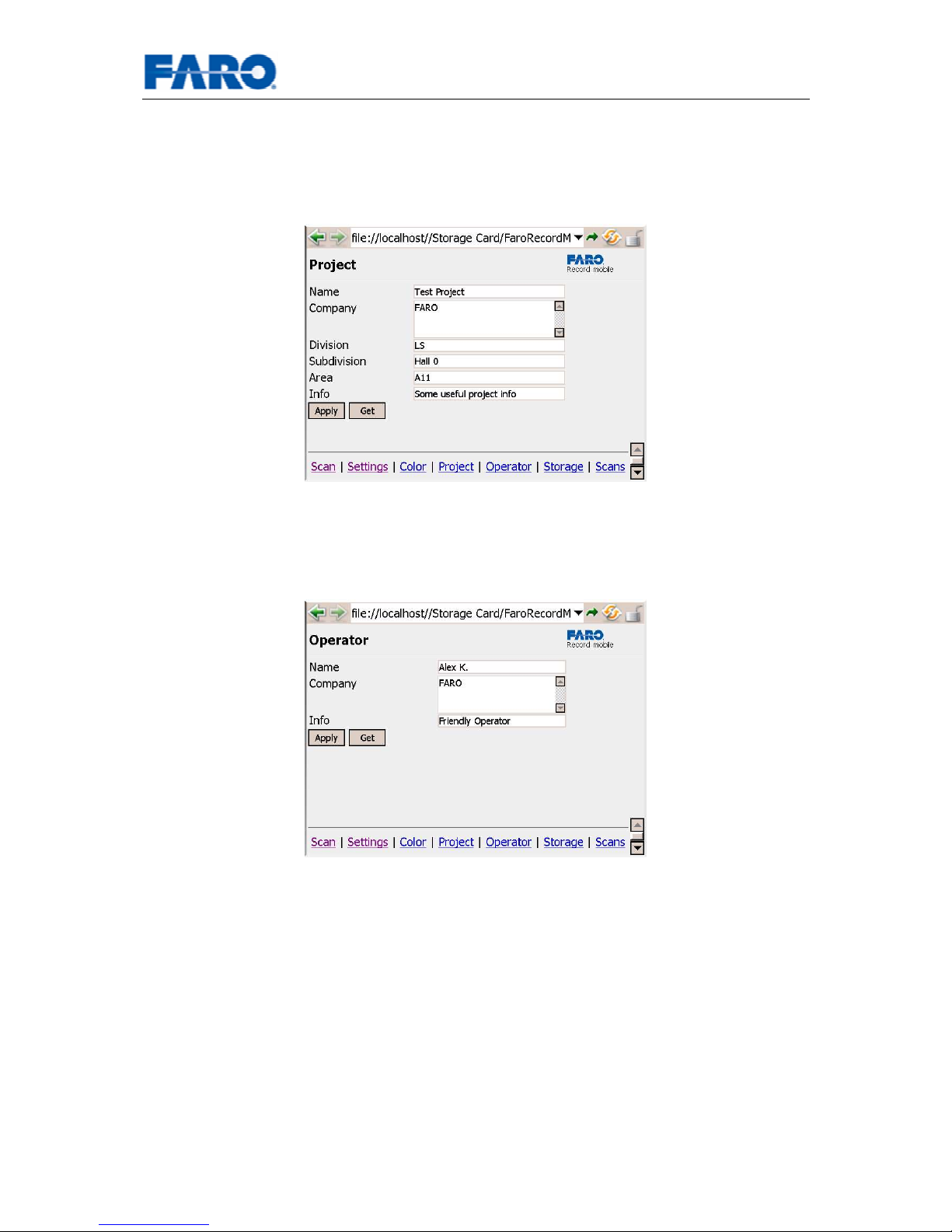
8.4.2 Settings Page
Fig.32 Settings Page
The vertical and horizontal ranges are the same as in FARO Record.
• Distance Range: is the maximum distance range of points which will be
taken.
• Resolution: Resolution of the scanner.
• Size: The number of rows and columns will be recalculated automatically
when pressing Apply and Automatic mode is enabled. If you want to change
the number of columns manually you should disable Automatic mode. Please
note that changing the number of columns manually results in scans which
have no 1:1 ratio between rows and columns. It is recommended to use this
only in special circumstances.
• Min. Reflection: Will filter out scan points with reflection value lower than
given here.
• Eye Safety Dist.: This eye safety distance gives the radius of safe operating
area known from FARO Record. Please note that the eye safety distance is
calculated only after pressing the Apply button!
8.4.3 Color Page
Fig.33 Color Page
If the scanner is equipped with the color option, you can checkmark the option Scan
with Color in order to get a colored scan. Using this checkbox corresponds to clicking
the button Start scan with color in FARO Record.
Before you start you have to choose the right camera mount (Non-winding or no
parallax) on tab Camera in the Scanner Parameter dialog using FARO Record (see
Page 42
User’s manual FARO Laser Scanner LS 42
© 2007 FARO Scanner Production
chapter 6.3.1.9). This setting will be stored on the scanner and normally only has to
be done once.
Other settings on this page correspond to the settings on tab Camera in the Scanner
Parameter dialog in FARO Record.
8.4.4 Project Page
Fig.34 Project Page
Settings on this page correspond to settings on tab Operation in the Scanner
Parameter dialog in FARO Record (see chapter 6.3.1.4).
8.4.5 Operator Page
Fig.35 Operator Page
Settings on this page correspond to settings on tab Operator in the Scanner
Parameter dialog in FARO Record (see chapter 6.3.1.5).
Page 43
User’s manual FARO Laser Scanner LS 43
© 2007 FARO Scanner Production
8.4.6 Storage Page
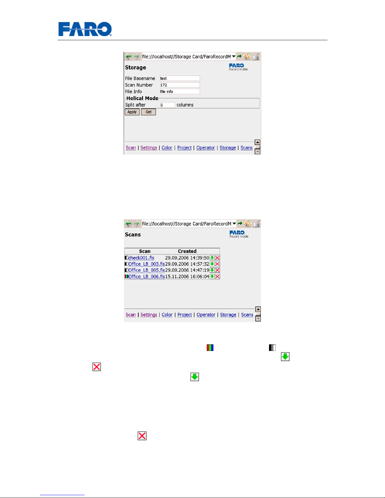
Fig.36 Storage Page
Settings on this page correspond to settings on tab Storage in the Scanner
Parameter dialog in FARO Record (see chapter 6.3.1.3). Notice that scans with
FARO Record mobile are always stored on the scanner.
8.4.7 Scans Page
Fig.37 Scans Page
On the Scans page all scans of the scans network drive of the scanner are shown.
For each scan there is an icon indicating color ( ) or regular scan ( ) followed by
scan name (e.g. test172.fls), date and time of creation a download link and a
delete link . By clicking on scan’s name you will see the scan image (see also
chapter 8.5). By clicking on download link you will be prompted to save the actual
scan file. Avoid saving scan files on the PDA’s own memory, because this would
consume most of PDA’s memory and you would get unexpected failures. But if you
have a CF (Compact Flash) or a SD (Secure Digital) or a similar card installed in your
PDA, you can easily save scan file on those cards. Of course you can also download
the scan files on a laptop or desktop computer.
By clicking on delete link you will be asked to confirm the deletion of this scan.
8.5 Viewing scans
There are two possibilities to open and see a scan’s image.
Page 44
User’s manual FARO Laser Scanner LS 44
© 2007 FARO Scanner Production
• By clicking on scan’s name shown as Last Scan on the Scan page just after
the scan was recorded, or
• By clicking on scan’s name on the Scans page as described in section
8.4.7.
Other links at the bottom are:
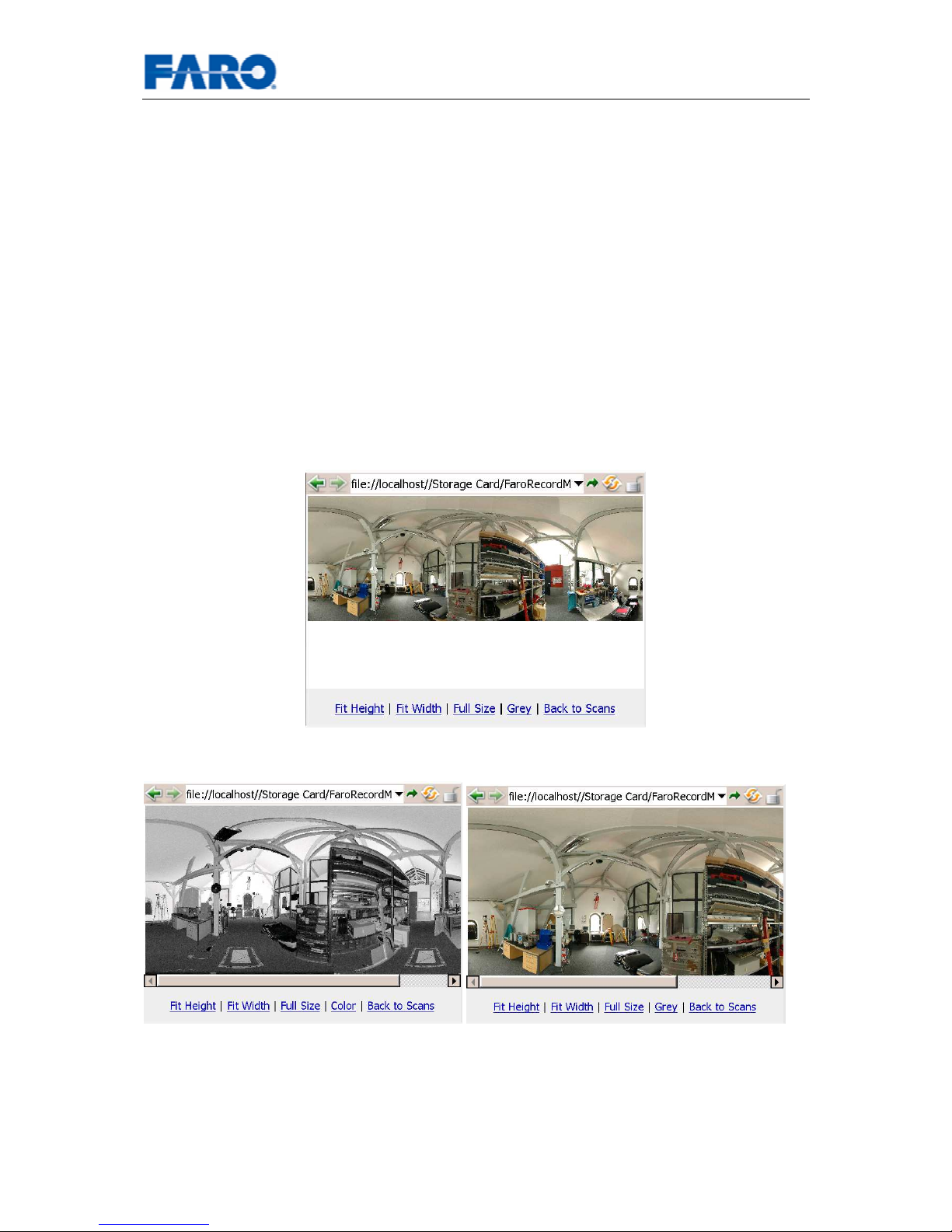
• Fit Height: This will resize the scan image so that the height is fit to the
screen.
• Fit Width: This will fit the width of the scan image to the screen, so you can
see the whole scan at once.
• Full Size: This will display the whole scan image without special screen
fitting. The navigation links are not displayed in this mode to maximize
viewing area. To get back from this mode use the Back button of your web
browser. The back button of Opera is the green arrow in the left top corner.
• Grey and Color links: These links switch between regular scan image and
colored image taken with the digital camera. If the scan has no color
information these links are not shown.
Fig.38 Viewing a scan in Fit Width mode
Fig.39 Regular scan image and colored image (in Fit Height mode)
Page 45
User’s manual FARO Laser Scanner LS 45
© 2007 FARO Scanner Production
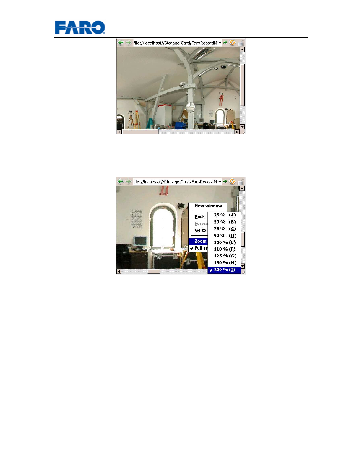
Fig.40 Color image in Full Size mode
When in Full Size viewing mode of Opera, you can use the built-in zoom features.
(Please note that this feature is not available with Internet Explorer Mobile from
Microsoft yet)
Fig.41 Zoom factors
Hold the pen on the PDA’s screen until a menu appears. Select Zoom and then the
zoom factor. Remember that this feature is a general zoom for any web content. If
switching back from Full Size mode this zoom factor will still be applied to the whole
web page. Please set it back manually to 75% as suggested before.
8.6 Auxiliary Files in the Scans Network Drive
There are auxiliary files in the scans network drive of the scanner for each scan.
These files are needed for FARO Record mobile in order to display the scan images.
They are not needed for processing the scans with FARO Scene!
If you want to delete scan files from the scans network drive with the help of the
Windows Explorer, please make sure to delete these auxiliary files also. The files are
named consistently with the scan file name, and have a suffix grey.jpg or color.jpg.
On the other hand, if you delete the auxiliary files accidentally the scan will not show
up in the scan listing of FARO Record mobile, even if the scan file itself still exists.
If you delete a scan file through the web interface like shown in previous section the
auxiliary files will be deleted automatically.
Page 46
User’s manual FARO Laser Scanner LS 46
© 2007 FARO Scanner Production
9 Cleaning Instructions for optics
ATTENTION: To avoid unnecessary damage or wear, only clean optics when
the degree of contamination requires cleaning for proper function.
Major contamination and improper handling to clean optics may impact the scanning
quality. Self-caused damages can result in a complete replacement of the part
at the expense of the customer.
• We recommend using latex gloves (acetone-proof). People suffering from
latex allergies should use other acetone-proof gloves. Lightly rub the gloves
after taking them off with laboratory cloths and acetone to remove grease and
dirt.
• Never touch the optical surfaces with bare hands;
if possible, do not touch with laboratory gloves either.
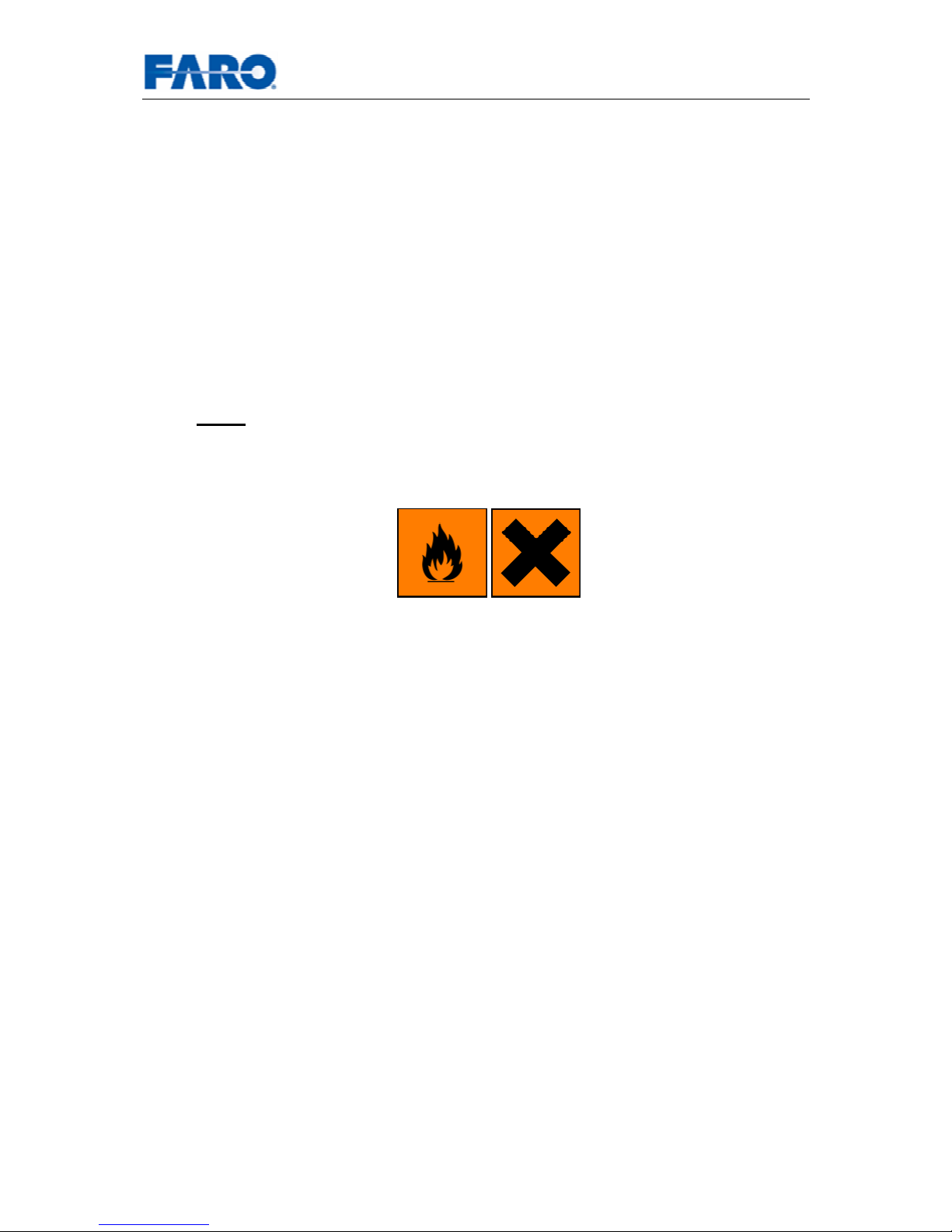
• Because of the hazardous materials, acetone and isopropanol, the optics
should be cleaned in a cleaning box with air exhaust, flowbox, or mask.
• ATTENTION: Before cleaning the mirror optics, cover the lens with a cap
and avoid any contact with the lens.
• Even small amounts of acetone on the lens may result in dullness of the
lens surface or cracks in the lens body.
• In the event acetone accidentally comes in contact with the lens,
IMMEDIATELY rinse with isopropanol or water (distilled, if possible).
What’s needed:
• Compressed air spray (oil-free - optical supply store)
• Acetone, isopropanol in spray bottle / dropping bottle
Other types of alcohol (methanol, ethanol) may be used instead of isopropanol
(pharmacy, laboratory supply store, chemical supply store)
• 1 Package lens tissue (optical supply store)
• 1 Package laboratory cloths (lint-free)
• 1 Pair of tweezers or forceps
• 1 Pair of non-powdered gloves (acetone-proof – latex)
Additionally for a greatly contaminated mirror:
• Mild neutral soap (optical supply store)
Page 47
User’s manual FARO Laser Scanner LS 47
© 2007 FARO Scanner Production
9.1 Slightly contaminated mirror
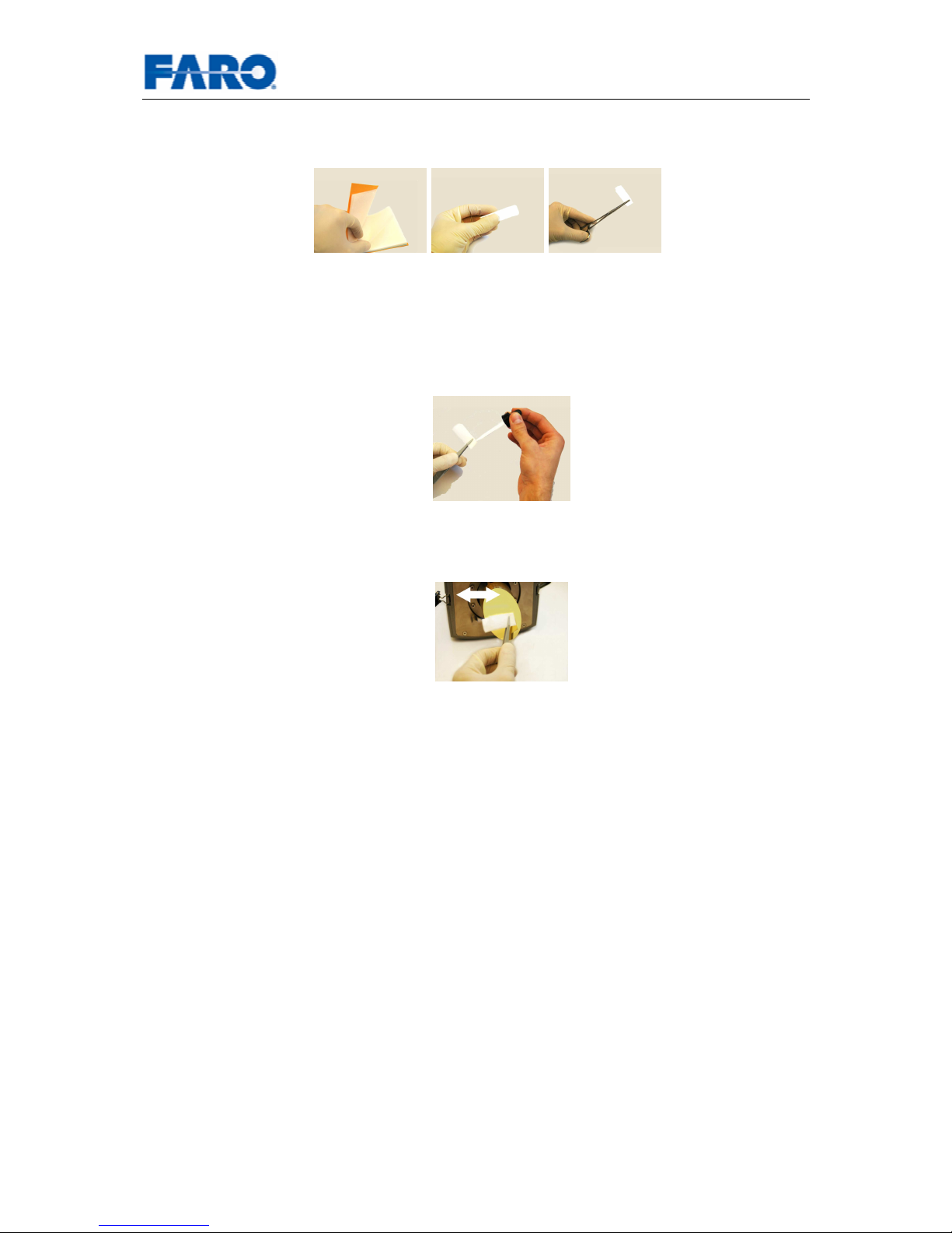
Handling lens tissue: Fold one piece of lens tissue and clamp it in the tweezers or
forceps.
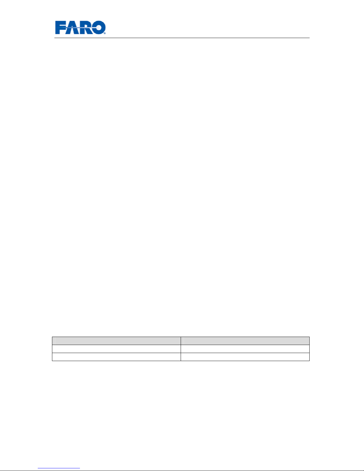
• First, use a little compressed air spray (oil-free) to clean the surface of the
optics.
• Mist the clamped lens tissue with a mixture of acetone and isopropanol (do not
soak). If necessary, wait a few seconds until some of the solution has
evaporated.
• Carefully clean the edge of the mirror. Avoid touching the mirror surface with
gloves.
• Mist another folded, clamped lens tissue with acetone / isopropanol. Starting
at the edge of the mirror apply light pressure and wipe across the mirror into
one direction. Repeat until the mirror surface is clean. Use a clean area of the
lens tissue (fold used lens tissue accordingly) or new lens tissue for each
wipe.
9.2 Greatly contaminated mirror
Folding laboratory cloths: Take several individual laboratory cloths out of the
package and fold twice. Set onto an oil-free surface.
• Fold the laboratory cloth and soak the edge in acetone. Carefully clean the
edge of the mirror.
• Completely mist a fresh folded laboratory cloth with mild neutral soap along
the edge.
• Starting at the edge of the mirror, apply light pressure and wipe across the
mirror. Repeat multiple times in linear direction.
• Then clean with acetone / isopropanol as described under 9.1.
Page 48

User’s manual FARO Laser Scanner LS 48
© 2007 FARO Scanner Production
9.3 Cleaning the receiver lens
Clean receiving lens as described under 9.1, BUT USE ONLY ISOPROPANOL! NO
ACETONE!
• Even small amounts of acetone on the lens may result in dullness of the
lens surface or cracks in the lens body.
• ATTENTION: To avoid unnecessary damage or wear, only clean optics
when the degree of contamination requires cleaning for proper function.
• Major contamination and improper handling to clean optics may impact the
scanning quality. Self-caused damages can result in a complete
replacement of the part at the expense of the customer.
9.4 Suppliers
Thorlabs, Inc. (http://www.thorlabs.com)
Edmund Optics (http://www.edmundoptics.com)
Gloves, lens tissues, laboratory cloths, tweezers, forceps
Kugler GmbH (http://www.kugler-precision.com)
Cleaning set
Page 49
User’s manual FARO Laser Scanner LS 49
© 2007 FARO Scanner Production
10 Appendix
10.1 FARO Laser Scanner LS error messages
- Scan data buffer overflow
Please check the connection between the operating PC and the scanner.
Make sure there is a functional communication with at least 100Mb/s.
If you get one of the following error messages, please contact you local
customer service team for assistance:
- Failure message received from motor controllers
One of the horizontal or vertical motors issued an error.
- Timeout: Motor home position
The horizontal motor couldn’t find its zero index.
- Internal Error: Invalid parameter
The scanner parameters are inconsistent.
- Failed to open communication line to scanner
The communication with the sensor module couldn’t be established
- Distance measurement tolerance exceeded
The white reference area on the base gave inconsistent measurements.
Please check cleanliness of reference area, mirror, and lenses.
- Timeout: Line sync signal
The mirror motor couldn’t find its zero index.
- Motor speed tolerance exceeded
The speed of the mirror motor isn’t uniform
10.2 FARO Laser Scanner LS data and power cable
The scanner is connected by a combined data and power cable from LEMO®.
Plugs -Part-No. Receptacles - Part-No.
FHG.1B.308.CLAD (90° bend) EGG.1B.308.CLL
FEG.2B.308.CLAD (straight) HGG.2B.308.CLL
Page 50

User’s manual FARO Laser Scanner LS 50
© 2007 FARO Scanner Production
Fig.42 Data and power cable - pin assignment
1
3
45
6
8
7 2
Soldering Side View
(1) +24 V
(2) +24 V
(3) GND
(4) GND
(5) LAN1 (orange/white)
(6) LAN2 (orange)
(7) LAN3 (green/white)
(8) LAN4 (green)
Page 51
User’s manual FARO Laser Scanner LS 51
© 2007 FARO Scanner Production
11 Product Environmental Information
Legislation is now in place within the European Union (EU) that regulates waste from
electrical and electronic equipment (WEEE). European Directive 2002/96/EC on
Waste Electrical and Electronic Equipment (the WEEE Directive) stipulates that
WEEE is now subject to regulations designed to prevent the disposal of such waste
and to encourage design and treatment measures to minimize the amount of waste
that is placed into the waste stream. The objective of the WEEE Directive is to
preserve, protect and improve the quality of the environment, protect human health,
and stimulate the practical use of natural resources. Specifically, the WEEE
Directive requires that producers of electrical and electronic equipment be
responsible for the collection, reuse, recycling and treatment of WEEE which the
Producer places on the EU market after August 13, 2005.
FARO Technologies, Inc., as a producer of electrical and electronic equipment, has
endeavored to meet these environmental responsibilities for managing WEEE. In so
doing, FARO is providing the following to inform its customers about the WEEE
collection process:
In order to avoid any potential dissemination of hazardous substances into the
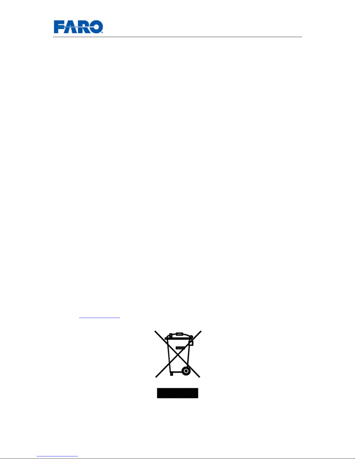
environment, FARO has labeled this product with the WEEE symbol (see below) in
order to alert the end-user that it should be disposed of within the proper waste
management system. That system will recycle, reuse, and dispose of materials from
this product in an environmentally sound way.
The symbol represented below, and found on this FARO Technologies product,
indicates that this product meets the European Directive 2002/96/EC on Waste
Electrical and Electronic Equipment. This symbol, only applicable in European Union
countries, indicates that when this product reaches the end of its useful life it should
not be disposed of with normal household or municipal waste, but in an established
waste stream for WEEE.
Each EU Member State country has established a system for the collection, disposal,
and recycling of WEEE. End-users in the EU should contact their local waste
administration system for collection instructions concerning this product.
Refer to
www.faro.com for further environmental information concerning this product.
Fig.43 WEEE Symbol
 Loading...