

FarmTek Polaris Operating Instructions Manual
FarmTek
Sport Timing Specialists
Polaris
Multi-Event Timer
Operating
Instructions
FarmTek, Inc.
1000 N Hwy 78, Ste D (972) 429-0947
Wylie, TX 75098 (800) 755-6529

©
FarmTek, Inc.
POLARIS TIMER CONSOLE
Timer Console Power
Batteries
The new Polaris timer is powered by four AA alkaline batteries instead of an AC adapter as in the past.
The timer runs 50 to 60 hours on a new set of batteries. Always turn the timer off before changing the
batteries and always replace all four batteries at the
same time – do not mix old and new batteries.
To check the battery level, follow these steps:
1) Press SETUP to access setup functions.
2) Press NEXT CHOICE until Check Battery is
displayed (just one or two presses).
3) Press ENTER to show remaining battery life.
4) Press SETUP to return to normal operation.
Keep in mind that when the console is first turned on
after being off for a while (e.g., overnight), the re-
ported battery level is artificially high for the first
half-hour or so of use.
When storing the timer console for an extended period, it is best to remove the batteries.
Low Battery Warning
A low battery icon is flashed in the upper right corner of the Status display when about 2 to 4 hours of
console battery life are left. Note that the battery
icon is also displayed whenever an electric eye in
the arena has a low battery. Check the console’s
battery level as described previously to see if it is
the reason the icon is flashing.
Power On/Off
Turn the Polaris timer on and off using the slide
switch located at the upper right corner of the timer
console.
Timer Connections
Connections on the rear of the timer console have
changed with the introduction of the new Polaris
timer. The
Power
jack is gone and in its position is
the
Input
jack. The
Input
jack is for connection of
optional input devices such as a bar code reader and
numeric keypad to be offered in the future. Do not
plug an AC adapter from an older FarmTek timer
into the
Input
jack on the new Polaris. It can cause
serious damage!
The
Display
jack is now called the
Output
jack,
however, its functions are the same: Output of scoreboard data and output of computer/printer data.
The functions of the
Horn
jack are unchanged from
the previous version of the Polaris timer: It provides
audio output of the horn sound to a PA system and
also connects to our stand-alone horn.
©
FarmTek, Inc.
WIRELESS ELECTRIC EYES
Operation
Batteries
The electric eyes operate over 70 hours from a 9 volt
alkaline battery (use only alkaline batteries). The
Power
lamp on the unit glows steadily while the bat-
tery is good and flashes when the battery is low.
To help detect an eye with a low battery, the Polaris
timer in the announcer’s booth flashes a low battery
icon in the upper right corner of its Status Display
when any electric eye in use has a low battery.
The electric eyes operate at least two hours after the
first indication of low battery. Note: The two hour
period is from the first time the low battery light begins flashing. If a unit with a low battery is turned off
and then later turned back on, the lamp may glow
steadily for some time before it starts flashing again.
This does not mean there are two more hours of operation remaining at this point.
Once the
Power
lamp begins flashing, it is simplest to
just replace the battery during the next break in your
event – don’t worry about trying to use the last few
hours of the battery.
When storing the electric eyes for an extended period
of time, always remove the batteries.
Helpful Hints
Even though the antennas
can be unscrewed, doing so
can cause problems: Do Not Remove the Antennas!
Placement of the electric eyes and the timer console
in the arena and the announcer’s stand can affect performance of the radio link. Note these guidelines:
1) Ensure an unobstructed line-of-sight between the
antenna on the electric eye and the antenna on the
timer console in the announcer’s booth. Verify
clear line-of-sight from down at the antenna’s
level – not from your standing eye level.
2) Position the timer console at least 2-3 feet from
major electronic equipment such as computers,
monitors, and the PA system.
Optical Interference from the Sun
When the electric eyes are setup with more than 100
feet between them, a late afternoon sun shining directly into the Photo-Receiver (the electric eye with
the antenna) can cause problems. A simple remedy is
to swap the electric eyes with each other so that the
sun shines into the face of the Photo-Transmitter instead (the electric eye without the antenna). Or, you
can construct a shade for the Photo-Receiver – see a
sample sun-shield to print and cut out on the web at:
farmtek.net/sunshield.htm.
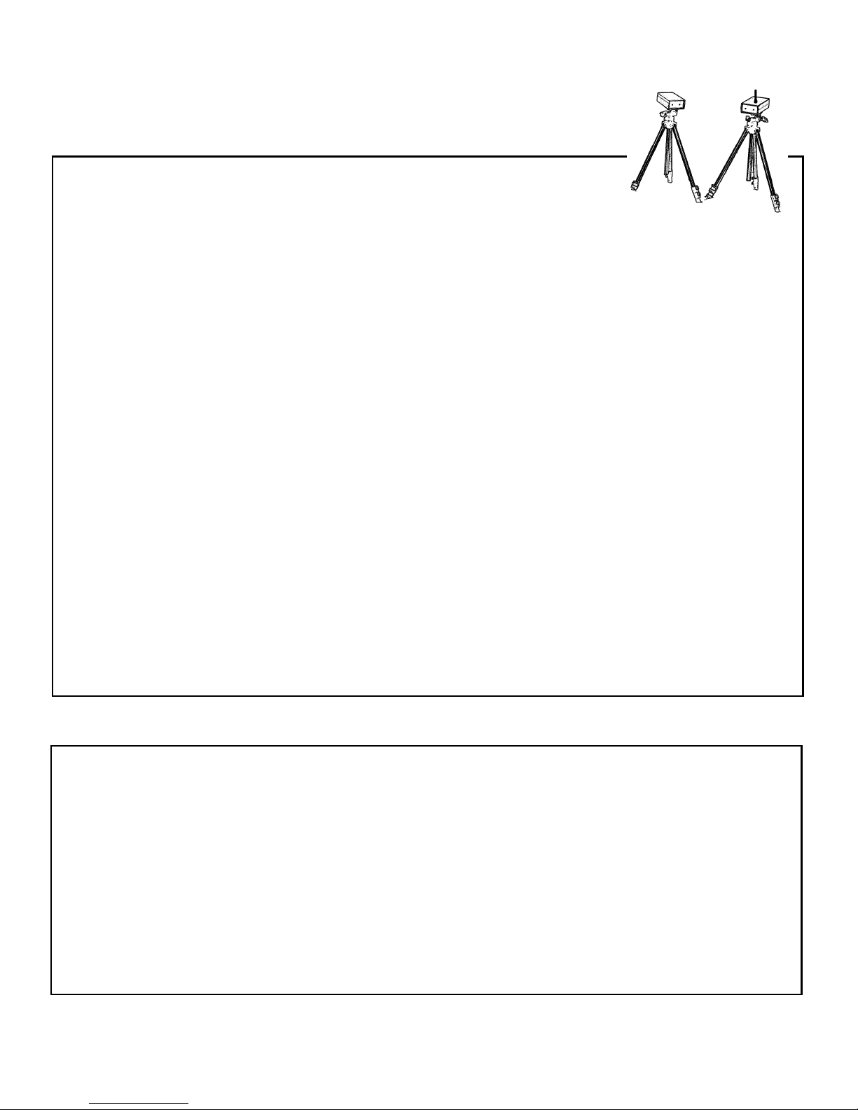
Two Timers At Once
Two complete timers can be used at the same time to
provide back-up for each other. However, when two
Photo-Transmitters (the infrared light source) are on
at the same time, they interfere with each other at the
Photo-Receiver. To prevent problems, set up both
complete timers, stacking the electric eyes on top of
each other. However, only turn on one of the PhotoTransmitters. Both Photo-Receivers will “see” the
beam, but since the beam is coming from just one
Photo-Transmitter, there is no interference.
Note: Older wired electric eyes may not “recognize”
the wireless Photo-Transmitter. In this situation, make
sure the one Photo-Transmitter that you turn on is the
older, wired Photo-Transmitter – both the wired and
wireless Photo-Receivers will operate from the older,
wired Photo-Transmitter.
Two Wireless Timers at Once
If the two timers in use are both wireless timers, then
in addition to the requirements already mentioned,
make sure the two Photo-Receivers (the electric eye
with the antenna) operate on different channels. The
channel number used by the Photo-Receiver is
stamped inside the battery compartment.

©
FarmTek, Inc.
Electric Eye ID Codes
WIRELESS ELECTRIC EYES (2)
Each wireless electric eye is permanently programmed with an electronic identification code. No
two units have the same ID code. The ID code is
transmitted along with other information whenever
the electric eye beam is broken or restored. For a set
of wireless electric eyes to work with a particular
timer console, the timer console must “know” the ID
code of the electric eye being used.
If you use a different set of electric eyes or a different
timer console than usual, you must have the timer
console “learn” the ID code of the electric eyes being
used as detailed below.
Note that the Polaris timer supports up to four sets of
electric eyes. These are referred to as Eye #1, Eye #2,
Eye #3 and Eye #4. The table below shows which
eyes are used for each event. If a new ID code is
learned for Eye #1, then all events that use Eye #1
are also affected. The same logic applies when the ID
code for any other eye is update
Event Eye #1 Eye #2 Eye #3 Eye #4
Barrel Racing
Start/Stop
Roping
Steer (Start) Header (Breakout) Heeler (Breakout)
Bull Riding
Team Penning
Start (Optional)
Cutting
Start (Optional)
Power & Speed
Start Stop/Start Stop
Show Jumping
Start/Stop Start/Stop Start/Stop
Lap Timing
Start/Stop
Autocross
Start Stop Split Time Split Time
Sprint/General
Start/Stop Start/Stop Split Time Split Time
Time Stamp
Time Message Time Message Time Message Time Message
Learning a New ID Code
To program a pair of eyes into the Polaris console:
1) Place the eyes at least four feet apart, facing each
other, and arrange them so that the eye with the
antenna is furthest away from you and the Polaris
timer console. Ideally, have the eyes on separate
counters or tables. Make sure all other pairs of
electric eyes are OFF.
2) On the timer console, press the SETUP button to
access the timer Setup options.
3) Press NEXT CHOICE until Set Eye#1 ID is
displayed. (For some events, like Roping and
Show Jumping, you can choose from two or three
different eyes – choose the one you need to set.)
4) When you are ready to break the electric eye
beam, press ENTER. The timer will display
Break Eye#1 Beam Now... (or the appropriate
message for the eye you selected).
5) Walk or pass something large through the beam.
As soon as the beam is broken, the timer momentarily displays the ID code for the eye.
That’s it! For events like Roping or Show Jumping,
repeat the procedure for other eyes, if needed.
Note: If the “Break Eye Beam Now…” message remains on the display, force a beam break by turning
the eye without the antenna off and then back on.
For events which can use more than two sets of eyes,
learning the ID code for Eye 3 or 4 enables those
eyes. Conversely, to disable an electric eye that is not
used, follow steps 2 to 4 for the eye you wish to disable, then abort the programming process by pressing
any button on the keypad. This disables the selected
electric eye.

©
FarmTek, Inc.
Overview of Operation
WIRELESS HANDSWITCH
The wireless handswitch adds flexibility to several
events supported by the Polaris timer. The wireless
handswitch can be used to start and stop the timer for
Bull Riding, Team Penning, Cutting, etc. For Ranch
Sorting, the handswitch is used to mark the split time
at which each cow is sorted. For Team Roping, the
handswitch is carried by the judge in the arena and is
set to stop the timer only. For Show Jumping and
Power & Speed events, the handswitch is used to
stop and start the timer when a jump is dislodged:
Pressing the handswitch while the timer is running
sounds two bursts of the horn and stops the timer.
Pressing the button again sounds the horn and re-
sumes timing. For Lap Timing, the handswitch can
be used in place of the electric eyes to allow manual
timing of laps.
The Average Time event is used for hand timing of
Roping, Steer Wrestling, Goat Tying, etc. This event
averages the times of two timekeepers and requires
at least one wireless handswitch. With a single
handswitch, one timekeeper uses the Start/Stop button on the timer console and the other timekeeper
uses the wireless handswitch. A second wireless
handswitch can be used so that neither timekeeper is
tied to the timer console.
Handswitch Operation
The wireless handswitches are designed for operation within about 100 feet of the timer console. The
handswitch is similar to the wireless electric eyes
and must be turned on by pressing the red power
button on the front panel. Once powered on, the
handswitch is operated by pressing the green button
on top of the handswitch with your thumb.
Two Handswitches Used at the Same Time
If the two handswitches are in use at the same time,
make sure they operate on different channels. The
channel number is between 0 and 3 and is stamped
on a small yellow sticker inside the battery compartment of the handswitch.
Handswitch ID Code
Each handswitch is permanently programmed with a
unique electronic identification code. For a
handswitch to work with a particular timer console,
the timer console must “know” the ID code of the
handswitch being used.
If you use a different handswitch or a different timer
console than usual, or if your handswitch is not
working with your console, have the timer console
“learn” the ID code of the handswitch(es) being by
using the Set HandSwitch ID option in the Setup
menu.
Batteries
The handswitch operates over 70 hours from a 9 volt
alkaline battery (use only alkaline batteries). The
Power
lamp on the unit glows steadily while the
battery is good and flashes when the battery is low.
The handswitch will operate at least two hours after
the first indication of low battery. However, the two
hour period is from the first time the low battery
light begins flashing. If a unit with a low battery is
turned off and then later turned back on, the lamp
may glow steadily for some time before it starts
flashing again. This does not mean there are two
more hours of operation remaining at this point.
Once the
Power
lamp begins flashing, it is simplest
to just replace the battery during the next break in
your event – don’t worry about trying to use the last
few hours of the battery.
When storing the handswitch for an extended period
of time, always remove the battery.

©
FarmTek, Inc.
HORN OPERATION
The wireless Polaris timer supports several different
horn options:
• Stand-alone horn.
• A horn built into some scoreboard models.
• The “PA Horn” (a direct connection between the
timer console and a PA system).
All horns provide the same functionality as described
in the instructions for each event. The primary difference is how each horn connects to the timer.
Note: To check horn operation, you can press the
HORN button on the timer console at any time to
sound the horn.
Mechanical Horns
Stand-Alone Horn
To connect the stand-alone horn, plug the gray cable
which exits from the horn into the
Horn
jack on the
rear of the timer console. Plug the black power cord
from the horn into a standard 120 volt outlet. Do not
hang or mount the horn by the wires which exit from
the horn. In a wet environment, orient the horn so that
the horn’s cables exit downwards.
Scoreboard Horn
The scoreboards which use light bulbs have a horn
built into the scoreboard. Whenever the scoreboard is
connected to the timer console for normal operation
(by connecting the scoreboard’s data cable to the
Output
jack on the timer console), the horn in the
scoreboard is also connected – no additional connection to the scoreboard is required to operate the horn.
PA Horn
Connection
The wireless Polaris console provides for a direct
connection between the timer console and a public
address system (PA system). The timer console contains a digitized recording of our loud, stand-alone
horn. The PA system performs as if a microphone is
in front of a stand-alone horn – except there is no
horn and there is no microphone!
To use the PA Horn, connect the “Timer to PA Cable” provided with the timer (10 foot cable with a
stereo phone plug on one end and an RCA phono
plug on the other end) from the
Horn
jack on the
timer console to a line input jack on your PA system.
(Line input jacks on a PA system are typically labeled
with names like “AUX”, “CD Input”, “Tape In”,
“Mix In”, etc.)
If a spare line input is not available, or you cannot
obtain the desired volume level, a cable to connect
the timer to a microphone input on the PA is also
available. Contact FarmTek for more information.
Disabling the Scoreboard Horn
If you are using one of the two larger scoreboards
which has a built-in horn, and you do not want the
horn in the scoreboard to sound, follow these steps to
disable the horn in the scoreboard:
a) Press SETUP to access setup functions.
b) Press NEXT CHOICE until Disable SB Horn
is displayed.
c) Press ENTER to disable the scoreboard horn.
Note: You can re-enable the scoreboard horn when
needed by picking Enable SB Horn in step (b).
Different Horn Tones
In addition to the standard bull-horn sound, other
horn tones can be selected:
a) Press SETUP to access setup functions.
b) Press NEXT CHOICE until Set Horn Sound
is displayed, then press ENTER.
c) Press NEXT CHOICE to scroll through the
available horn tones. Press ENTER when the
desired tone is displayed.
©
FarmTek, Inc.
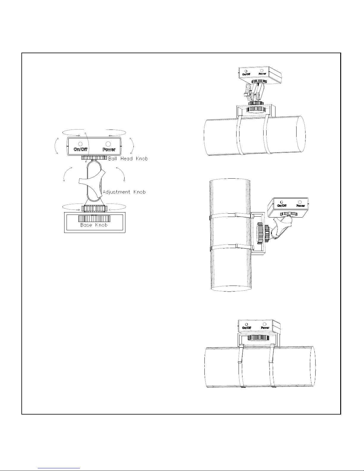
Overview
QUICK-MOUNT
The Quick Mount is a quick and flexible way to
mount the Wireless Electric Eyes to virtually any
fence pipe, cattle panel, etc. It's great for temporary
or permanent installation of electric eyes for roping.
The combination of a ball head, pivoting support
arms, and a rotating base allows numerous positioning adjustments as illustrated below.
The Quick Mount attaches to fences and posts using
plastic tie-wraps. Leave the mount attached for just
the night, or leave it attached for months! Additional
tie-wraps are available at most hardware and autoparts stores.
Loosening the Adjustment Knob allows movement of
the ball head and pivoting of the holding arms. Loosening the knob about 1/2 turn frees the ball head to
rotate and swivel. Loosening the knob slightly more
allows the arms to pivot.
Loosening the Base Knob on the Quick Mount allows
rotation of the Quick Mount on its base. This rotation
can be used to orient the holding arms so they pivot in
the direction you require.
Note: Keeping the eye “flat” as illustrated is only
required when mounting the eye with the antenna.
The electric eye without the antenna can be mounted
in any orientation required.

Event
Instructions
©
FarmTek, Inc.
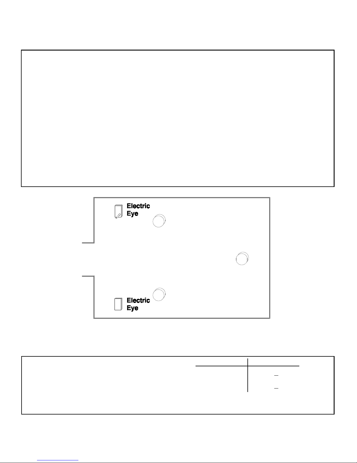
Preparation For Use
BARREL RACING (1)
1) Attach each electric eye to a tripod. Place the eyes
on opposite sides of the arena to form a start/stop
line between them. Extend tripod legs fully to ensure the electric eyes are high enough to be broken
by the horse's body (not its legs).
2) Turn the electric eyes ON. The power indicator
lamp on each unit should glow steadily. If the indicator is blinking, the battery is low and should
be replaced.
3) Align the electric eyes. The electric eye on the
opposite side of the arena should be directly inline when sighting down either line on top of the
electric eye (left to right alignment), and when
sighting down the crack on the side of the electric
eye (up and down alignment).
4) Turn on the timer console in the announcer's
booth. The power switch is located at the upper
right corner of the timer.
5) The current event type (Barrel Racing, Roping,
etc.) is shown on the Status display on the timer
console. If BARREL RACING is not displayed, se-
lect the Barrel Racing event as follows:
a) Press SETUP to access Setup functions.
b) Press ENTER to select a new event.
c) Press ENTER to select Barrel Racing.
6) Walk through the electric eye beam to force the
eyes to send a message to the timer console. This
makes the timer console update its electric eye
alignment indicator (see below).
Typical Barrel Racing Layout
Checking Eye Alignment
The bottom right corner of the Status display shows
the alignment status of the electric eyes. When the
eyes are aligned, the eye number is displayed (“#1”).
If not aligned, or if the beam is broken, “x” is shown.
Alignment Display Shows
Eyes aligned
Eye #
1
Not aligned (or
beam broken)
Eye #
X
Important! When setting up the electric eyes, always take time to align the eyes as outlined above – even if the
timer indicates the eyes are aligned. This ensures a strong alignment instead of a possibly marginal alignment.

©
FarmTek, Inc.
Timer Operation
BARREL RACING (2)
When the rider enters the arena and breaks the beam,
the timer automatically begins timing from zero. The
timer does not need to be reset to zero before the
rider starts! Once broken, the beam is ignored for
about two seconds to allow dust to settle.
As the rider completes the run and breaks the beam
again, the timer stops and shows the final time. The
timer is now ready for the next rider! (As when starting the timer, the beam is ignored for about two seconds after stopping to allow dust to settle.)
Useful Features
Manual Start/Stop
The START/STOP button starts and stops the timer
just as if the electric eye beam had been broken.
Accidental Beam Break
If the timer accidentally stops during the middle of a
run, the rider can still be accurately timed. Pressing
the RESTART button resumes timing as if the timer
had never been stopped. As long as RESTART is
pressed before the rider finishes, the time is not lost.
Locking Out The Electric Eyes
For events which require the rider to pass through the
beam multiple times during a run, you can manually
or automatically disable the eyes during the run, then
re-enable the eyes prior to the final pass.
To manually disable the electric eyes, press the EYES
OFF button. "Off" is flashed over the electric eye
alignment display while the eyes are off. To re-enable
the electric eyes, press the EYES ON button.
To automatically ignore one or more passes in the
middle of a run, choose "Eye Off Setting" in the
setup menu, key in the number of passes to ignore
and then press ENTER. Setting the number of passes
back to zero, or turning the timer off and back on,
restores normal operation.
Previous Time Recall
Use the PREV and NEXT keys to scan back and forth
through previous times. The previous time display is
removed after about ten seconds, or by pressing any
other key. You may view a previous time even while
the timer is running.
Skipping a Rider / No Time
If using the optional printer, pressing the NO TIME
button prints "-- No Time --" on the printer. This ensures a line is present on the printer for each contestant registered to ride.
Penalties
Entering a Penalty
With the timer stopped, press the SCORE/PENALTY
button. Then, key in the penalty, followed by the
ENTER button. Pressing the decimal point button
moves the input cursor to the right of the decimal.
However, zeros to the right of the decimal do not
need to be entered.
After the penalty is entered, the Time display is updated to include the penalty. The Status display shows
the original time and the penalty value. If a scoreboard is connected, it shows the time including
penalty. If a printer is connected, an additional line is
printed showing the penalty and time with penalty.
Correcting Mistakes
To correct a mistake while entering a penalty, press
and hold down the CLEAR TIME button until the
timer beeps and the penalty value is cleared to zero.
If ENTER has already been pressed, simply start the
penalty entry process over – the new entry replaces
the previous penalty.
©
FarmTek, Inc.
Preparation For Use
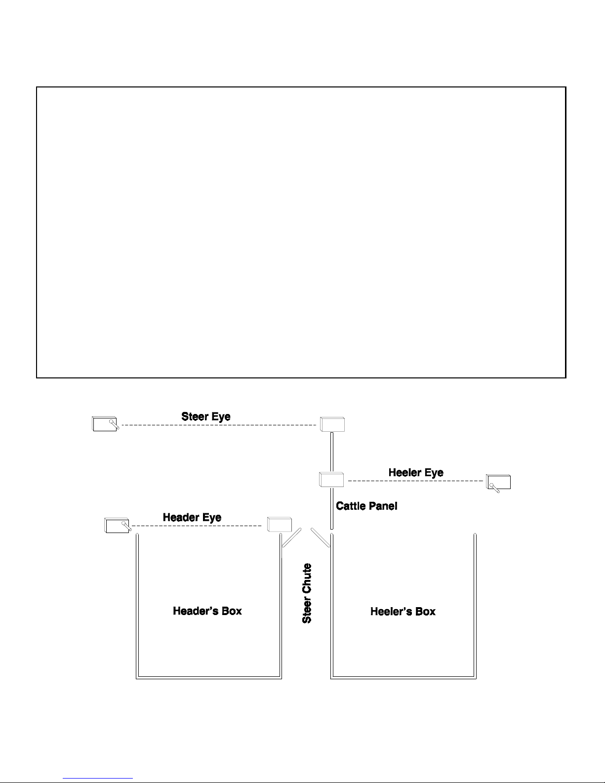
ROPING (1)
1) Decide where and how each electric eye pair will
be mounted. A typical set-up is shown below (the
heeler eye is optional). Choose eye locations that
are not likely to be hit by riders or the steer.
2) Mount each electric eye on a Quick-Mount or a
tripod. It is best to orient the eye which has the antenna such that the antenna is pointed straight up.
The eye without the antenna can be oriented as
convenient. Note the flexible positioning provided
by the Quick-Mount allows you to “recess” the
eye out of the way slightly.
3) Turn the electric eyes ON. The power indicator
lamp on each unit should glow steadily. If the indicator is blinking, the battery is low and should
be replaced.
4) Align the electric eyes. The opposite electric eye
should be directly in-line when sighting down either line on top of the eye (left to right alignment),
and when sighting down the crack on the side of
the eye (up and down alignment).
5) With the timer console OFF, connect the timer
console to whichever horn you are using (see the
Horn Operation instruction page.)
6) Turn on the timer console in the announcer's
booth. The power switch is located at the upper
right corner of the timer.
7) The current event type (Barrel Racing, Roping,
etc.) is displayed on the timer. If ROPING is not
displayed, select the Roping event as follows:
a) Press SETUP to access Setup options.
b) Press ENTER to pick a new event.
c) Press NEXT CHOICE until Roping is dis-
played.
d) Press ENTER to select the Roping Event.
8) Walk through each eye beam to force the eyes to
send a message to the timer console. This makes
the timer console update its electric eye alignment
indicator (see the next page).
 Loading...