

Page 1

111628M FodderPro 2.0
Micro System
"...grow your own nutrient-rich fodder..."
*Actual system may differ slightly from what is shown.
©2018 FarmTek
All Rights Reserved. Reproduction
is prohibited without permission.
Revision date: 09.25.18
®
1
Page 2

Important Information
READ THIS DOCUMENT BEFORE YOU BEGIN
Thank you for purchasing the 111628M FodderPro 2.0 Micro System. When properly assembled and maintained, this product will provide years of reliable
service. This guide includes important information needed to safely assemble and maintain the system. Read these instructions before you begin.
SAFETY PRECAUTIONS
• Wear eye protection.
• Wear gloves when handling metal tubes.
• Use a portable GFCI (Ground Fault Circuit
Interrupter) when working with electric power tools
and cords.
REQUIRED TOOLS
The following list identifies the main tools needed to
assemble the fodder system. Additional tools and
supports may be needed.
• Tape measure and marker
• Variable speed drill (cordless with extra batteries
works best) and drill bit set with a 9/32" & 7/16" bit.
• Small hammer and gloves
• PVC Tube Cutting Tool
• Level 2' (or longer)
• Wrench set or adjustable wrenches
• Socket Set with Ratchet
• Straight Screw Driver
• 1-3/8" hole saw bit for the drain manifold—Step Bit
recommended.
• Adjustable pliers
• 5/8" nut driver (or 5/8" socket)
• Ladder or work platform to work at the height of
the fodder system frame.
ASSEMBLY PROCEDURE
Following the instructions as presented will
help ensure the proper assembly of your fodder
system. This manual describes how to assemble a
single 111628M FodderPro 2.0 Micro System.
The steps outlining the assembly process are as
follows:
1. Verify that all parts are included in the
shipment. Notify customer service for
questions or concerns.
2. Read these instructions and all additional
documentation included with the shipment
before you begin.
3. Gather the tools and assistants.
4. For best results, assemble the components
in the order they are presented in these
instructions.
UNPACK AND IDENTIFY PARTS
The following steps will ensure that you have all
the necessary parts before you begin assembly.
1. Unpack the contents of the shipment and
place where you can easily inventory the
parts. Refer to the Bill of Materials/Spec
Sheets.
2. Verify that all parts listed on the Bill of
Materials/Spec Sheets are present. If anything
is missing or you have questions, consult
the Pictorial Parts Guide and all diagrams for
clarification, or contact Customer Service.
QUICK START GUIDE
For a quick overview of this product and its
components, consult the Quick Start Guide at the
back of these instructions.
ELECTRICAL WARNING
Fodder frame is metal and will conduct electricity!
Exercise caution if working around or on the
frame with electric power tools. Use cordless,
battery-power tools.
CONSULT THE SERVICES OF A QUALIFIED
ELECTRICAL TECHNICIAN WHEN INSTALLING
ANY PUMPS, ARTIFICIAL LIGHTING,
OR OTHER ELECTRICALLY POWERED
ACCESSORIES.
OPEN SYSTEM
The 111628M FodderPro 2.0 Micro System is
an open system, which means that the water
is not recycled for use in the fodder system.
Unlike a closed system where the water is
stored in a reservoir and recycled, the open
system requires a water source and a drain to
accept the unused water. The unused water can
be recycled for use in other applications such
as watering other plants; however, to promote
healthy fodder growth, it is not recommended
for reuse in the fodder system.
2
111628M Revision date: 09.25.18
Page 3
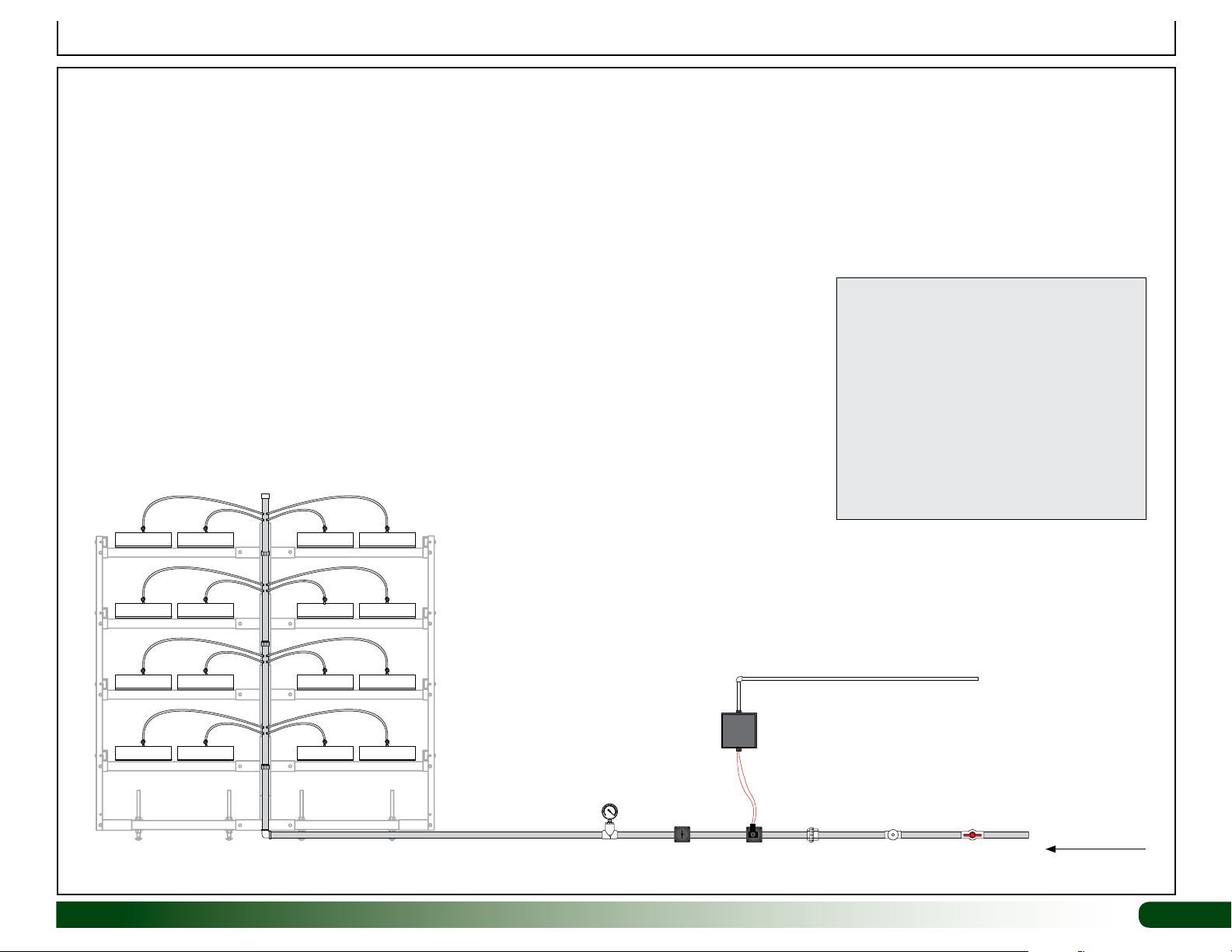
Connecting a Stand-Alone Unit to a 3/4" Main Supply Line
The 111628M FodderPro 2.0 Micro System includes all the components to assemble the main fodder frame, 6' channels, drain manifold, and supply manifold. Additional
components needed for the system are not included and require an additional purchase. These components—required, recommended, and optional—are noted in the diagram
below. Contact your sales representative for additional information and to purchase the additional components.
Consult the services of an electrician and/or professional contractor during assembly and when attaching the main water supply line to the fodder system. The diagram below
shows the basic items needed to supply and control the water to the fodder system.
ATTENTION: Stand-Alone System: Connect the main water supply to the top or bottom of the supply manifold. Diagram below shows a bottom connection.
WF2990
Slip Cap
NOTE: The 3/4" WF3311 ball valve connected
to the 3/4" main water supply line and the
WF2990 slip cap connected to the top of the
supply manifold are included with the fodder kit.
Timer
(required)
Additional Requirements for this Open System:
• Floor Drain (or method to manage unused
water)
• Level, solid surface to support assembled
fodder system
• Light Source–natural or artificial or a
combination of both
• Electricity
• Water Source
Electrical Power
(required)
Revision date: 09.25.18 111628M
3/4" PVC Pipe and Fittings
(required–additional purchase)
Pressure Gauge
(required)
Coupler for
Solenoid
(required)
maintenance
(recommend)
Water Meter
(optional)
15
20
10
25
5
0
30
psi
Pressure
Regulator
WF3311
3/4" Main Shut-Off
Ball Valve (included)
Water
Source
(required)
(required)
3
Page 4
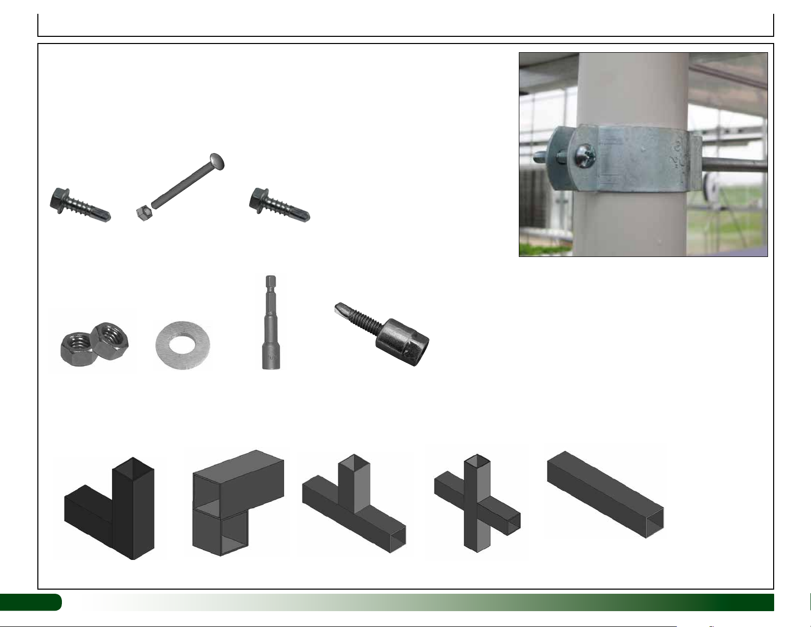
PICTORIAL GUIDE
The following graphics and photos will help identify the different
parts of the fodder system. (Some parts may not be shown.)
Quantity when noted is in ( ) following the stock number.
Important Information
111907
FA4482B
Tek Screw
FALB04B 3/8"
Nuts (6)
112502 Carriage Bolt (8)
FALB08B Nut (16)
FAME09B Flat
Washer (16)
FA4472B (6)
Tek Screw
100441 (2) Nut Setter
100442 (1) Nut Setter
Components for hanger brackets: FAK26 threaded
rods (2), 111907 conduit hangers (2), and FALB04B
nuts (3 per bracket assembly).
ATTENTION: Drill the mounting hole in the 111907
hanger bracket to 7/16" if needed to accept the 3/8"
threaded rod. Exercise caution. Clamp the hanger
bracket in a vice before drilling!
111906 1" Sammy
for 3/8" Threaded rod (2)
(12) S15P048 @ 48"
(16) S15P027 @ 27"
104625 (4)
111485 (16)
104626 (2)
104627 (8)
4
(2) 111628A @ 55 3/4" drilled (End Frame)
111628M Revision date: 09.25.18
Page 5
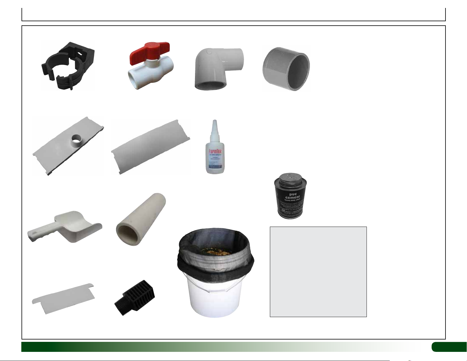
PICTORIAL GUIDE (continued)
Important Information
106808 (3) WF3311 (1) 3/4" Ball Valve
111029 (16)
End Cap w/ Outlet
105794
111560 (30') 2" PVC
111030 (16)
End Cap No Outlet
WF6682 (16)
112509 (3)
Adhesive
WF6717 (9) 2" Slip Caps
WF2990 (1) 3/4" Slip Cap
WF6990
PVC Cement
and
113372 Purple
Primer
PVC PRIMER & PVC CEMENT
Follow all directions printed
on pvc primer and cement
containers. Purple color of
primer does not fade! Use
caution during application to
reduce spills and over application
at joints.
111822 (1)
Seed Spreader
111303 Seed
Screen (16)
Revision date: 09.25.18 111628M
Prime all joints before
assembly.
107651 Bucket (2) and
111041 Soaker Bag (2)
5
Page 6
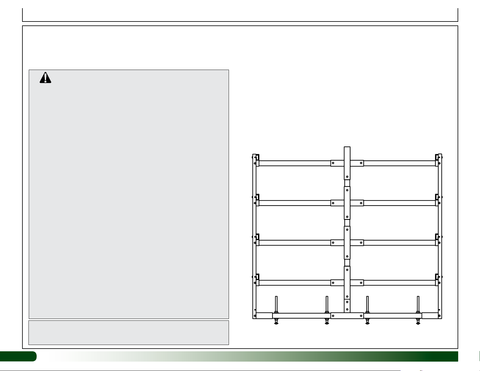
Important Information
SPECIAL NOTES AND CAUTIONS
The support frame for the 111628M FodderPro 2.0 Micro System is
designed to save assembly time and to better serve your growing needs.
Before you begin, read the information that follows.
CAUTION!
DO NOT CLIMB ON FRAME!
TO PREVENT INJURY AND POSSIBLE DAMAGE TO THE
FODDER SYSTEM AND RELATED COMPONENTS, NEVER
CLIMB ON THE ASSEMBLED OR PARTIALLY ASSEMBLED
FRAME.
NEVER USE THE FRAME ENDS AS A LADDER TO REACH THE
UPPER LEVEL OF THE FODDER FRAME!
ALWAYS POSITION THE FODDER CHANNELS ON THE
DIFFERENT LEVELS IN A WAY THAT EVENLY DISTRIBUTES THE
WEIGHT. NEVER LOAD ALL HEAVY CHANNELS ON ONE SIDE
OR ON THE TOP LEVEL OF THE ASSEMBLED FRAME. ALWAYS
PLACE HEAVY CHANNELS ON THE LOWER LEVELS ON EACH
SIDE OF THE FRAME.
NEVER REMOVE MATURE FODDER FROM CHANNELS ON
ONE SIDE OF THE FRAME ONLY. ALTERNATE FROM SIDE
TO SIDE TO MAINTAIN EVEN WEIGHT ON THE FRAME WHEN
HARVESTING FODDER.
AFTER FRAME SLOPE IS SET, ANCHOR THE BASE RAIL
OF EACH FRAME END TO THE CONCRETE USING ANCHOR
BOLTS WHEN POSSIBLE. PURCHASE BOLTS LOCALLY OR
CALL YOUR SALES REPRESENTATIVE FOR ADDITIONAL
INFORMATION.
CONSULT THE SERVICES OF A QUALIFIED CONTRACTOR FOR
OTHER WAYS TO ANCHOR YOUR SYSTEM WHEN IT IS NOT
POSITIONED ON CONCRETE.
ATTENTION: CONSULT ALL DIAGRAMS AND THOSE NEAR THE
BACK OF THIS GUIDE TO IDENTIFY CRITICAL DIMENSIONS, PART
NUMBERS, AND PART LOCATIONS FOR THE FODDER FRAME.
6
Diagram above shows the end frame for your 111628M
FodderPro 2.0 Micro System.
111628M Revision date: 09.25.18
Page 7
Assembly Instructions
ASSEMBLE MAIN FRAME: Base Tubes with Adjustable Levelers
1
Consult the Quick Start section of this guide for an overview of the system and
additional diagrams. Gather the parts and complete the steps that follow to
assemble the two end frames.
Required parts for base tubes and levelers:
• (2) 104626 3-Way Connectors
• (2) 111628A Square Tube (drilled) for end base rails
• (8) 112502 carriage bolts, (16) FAME09B flat washers, & (16) FALB08B nuts
• FA4482B Tek Screws and 100441 Magnetic Nut Setter
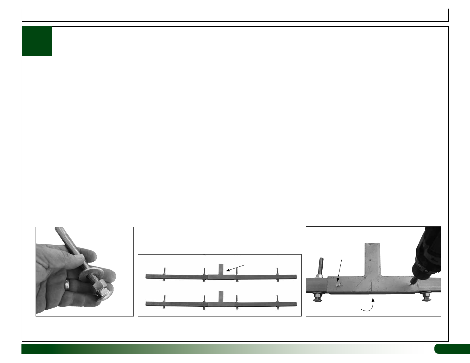
ATTENTION: Install Tek screws as shown for best results and a uniform appearance. Review all diagrams for clarification.
Complete these steps:
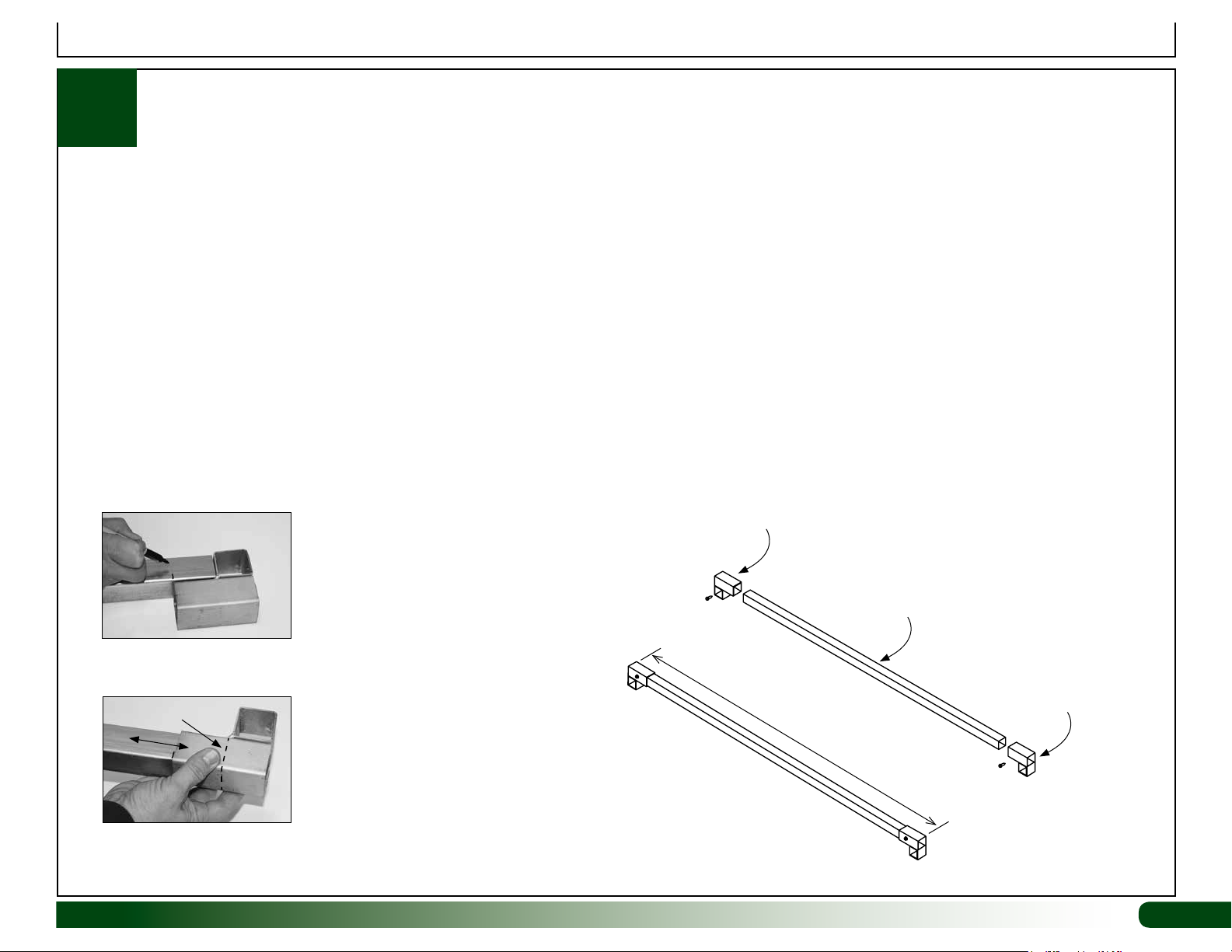
1. Take the carriage bolts, nuts, and flat washers and assemble as shown in Figure 1.
2. Assemble the two end base rails as shown in Figure 2. The 3-way connector should be loose between the levelers at this time.
3. Locate the center of each 3-way connector and mark with a pencil or marker.
4. Align the center mark on each connector with the center of the base rail and secure the connector to the base rail as shown in Figure 3.
5. Continue by installing the vertical frame tubes.
FA4482B Tek
104626
3-Way
Connector
111628A
111628A
FIGURE 1: Assemble levelers as shown. FIGURE 2: Assemble base rails as shown. The 3-way connector
is loose at this point. Levelers should be finger-tight to allow for
adjustments once the system is assembled and in position.
Revision date: 09.25.18 111628M
FIGURE 3: Center the connector on the base rail and
secure using two (2) FA4482B Tek screws.
Screw
Mark the center
of connector.
7
Page 8
Assembly Instructions
ASSEMBLE MAIN FRAME: Support Frames
1
Gather the parts and complete the steps that follow to
assemble the two (2) support frames.
Required parts for each support frame:
• (1) Assembled base rail (from previous page)
• (4) 104627 4-Way Connectors
• (1) S15P048 Square Tube (plain) for vertical support
• FA4482B Tek Screws and 100441 Magnetic Nut Setter
ATTENTION: Install Tek screws as shown for best results and a uniform
appearance. Review all diagrams for clarification.
Complete these steps:
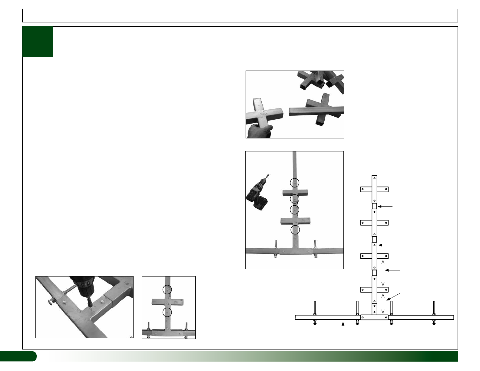
1. Take the S15P048 tube and slide one 4-way connector onto one end.
Slide the end of the tube into the 3-way connector of the base rail and
secure using two (2) Tek screws (Fig 1).
FIG. 3
2. Using the diagram to the right, position the 4-way connector as shown
and secure to the vertical tube using two (2) Tek screws (Fig. 2).
3. Move to the top of the vertical tube and slide three (3) more 104627
connectors onto the tube (Fig. 3).
4. Using the diagram to the right and in the Quick Start section, space each
connector on the tube and secure using two (2) Tek screws (Fig. 4).
5. Repeat the steps to assemble the remaining support frame.
6. Continue with the next procedure.
8
8
FIG. 1
FIG. 2
FIG. 4
S15P048
FA4482B
Tek Screws
9-3/4" between
connectors.
8" between
connectors.
This level only.
Assembled Base Rail with Levelers
111628M Revision date: 09.25.18
Page 9
Assembly Instructions
ASSEMBLE MAIN FRAME: Attach Support Arms (End Frames)
1
Gather the parts and complete the steps that follow to attach the
support arms to the assembled end support frames.
Required parts:
• (2) Assembled end support frames (from previous page). These include
the longer 111628A base rail.
• (16) S15P027 Square Tube (plain) for support arms
• FA4482B Tek Screws and 100441 Magnetic Nut Setter
ATTENTION: Install Tek screws as shown for best results and a uniform
appearance. Review all diagrams for clarification.
Complete these steps:
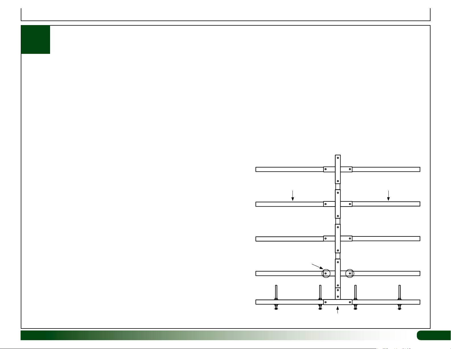
1. Position one end support frame on a flat surface.
2. Slide one S15P027 square tube into the lower 4-way connector and
secure it in place using an FA4482B Tek screw.
3. Repeat this process to attach all remaining support arms to complete the
first end support frame. See completed end support frame to the right.
ASSEMBLE END SUPPORT FRAME
S15P027
S15P027
4. With assistance, carefully move the frame to the location where the
fodder system will be assembled.
5. Repeat the above steps to assemble the remaining end support frame.
6. Continue with the assembly of the two (2) long base rails as shown on
the next page.
Revision date: 09.25.18 111628M
FA4482B
Tek Screws
111628A Base Rail
9
Page 10
Assembly Instructions
ASSEMBLE MAIN FRAME: Two (2) Base Rails
1
Gather the parts and complete the steps that follow to assemble the two (2) long base rails.
Required parts for each base rail:
• (1) S15P048 Square Tube (plain) for base rail
• (2) 104625 2-Way Connector
• FA4482B Tek Screws and 100441 Magnetic Nut Setter
Complete these steps:
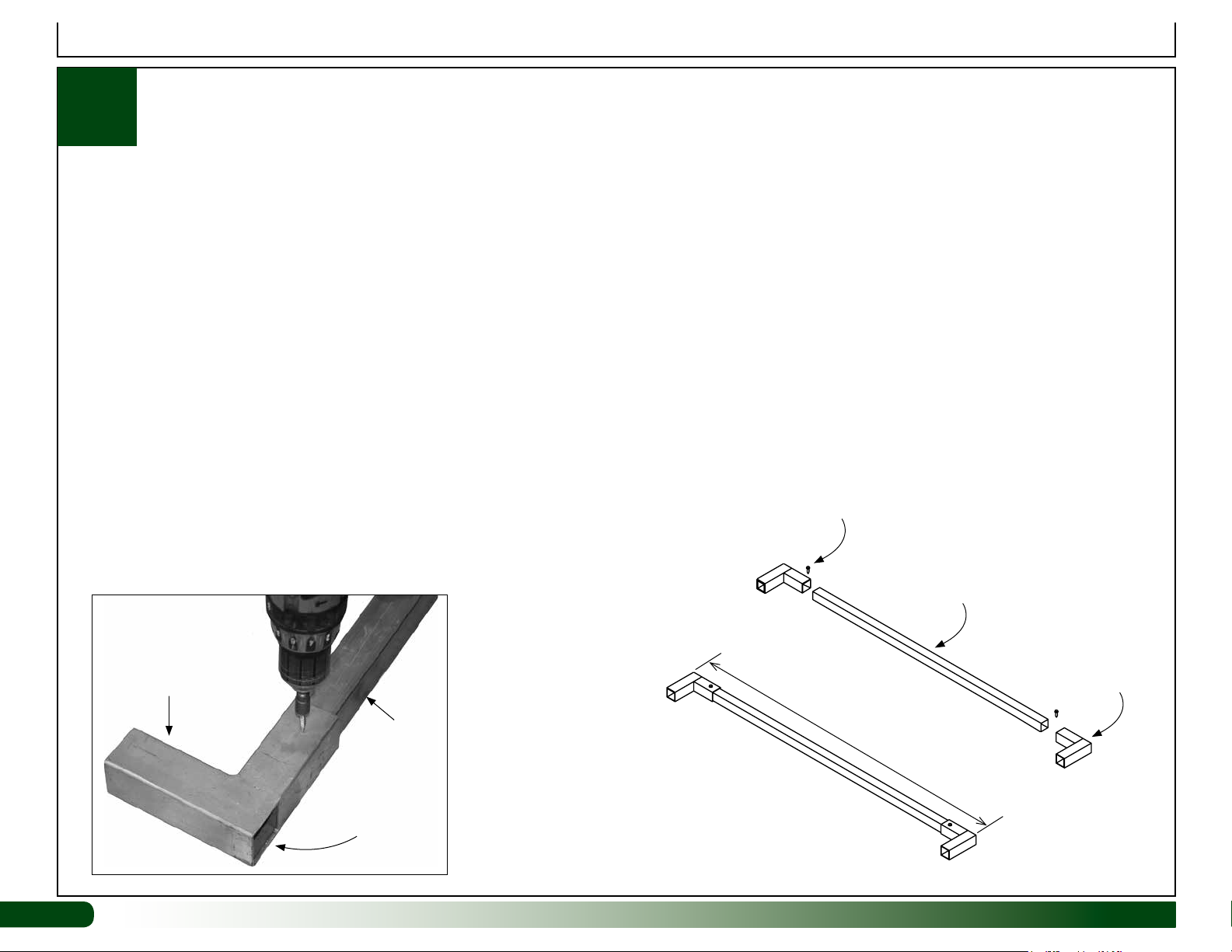
1. Attach one 2-way connector to each end of the tube as shown. Verify that each connector is tight to the end of the tube. Secure using one Tek screw
for each connector. Verify that the length of the assembled tube is 51 1/2".
2. Repeat the steps to assemble the remaining base rail.
3. Continue by assembling the outer frame tubes.
Slide connector on the
base rail and secure using
Tek screws.
10
10
104625
Connector
S15P048
Base Rail
Open end of
connector
Length 51 1/2"
outside-to-outside
ASSEMBLED BASE
RAIL
S15P048
Base Rail
Open end of
connector
111628M Revision date: 09.25.18
Page 11
Assembly Instructions
ASSEMBLE MAIN FRAME: Outer Frame Tubes
1
Gather the parts and complete the steps that follow to assemble the outer frame tubes.
Required parts for each outer frame tube:
• (1) S15P048 Square Tube (plain) for base rail
• (2) 111485 2-Way Square Tube Fittings
• FA4482B Tek Screws and 100441 Magnetic Nut Setter
Complete these steps:
1. Using Figures A and B, mark the S15P048 tube using a 111485 fitting as a template.
2. Attach a 2-way connector to each end of the tube as shown. Secure using one Tek screw for each connector. Verify that the length of the assembled
tube is 51 1/2". Do not install outer frame tube flush with the end of the connectors. The smaller off-set tube of the connection slides over each
shelf support tube attached to the end frames. See diagrams and photos.
3. Repeat the steps to assemble all remaining outer frame tubes.
4. Continue by assembling the main frame.
Slide this fitting onto the
base rail and secure
using Tek screw.
Fig. A: Pre-mark tube for
easier assembly.
Approximate End of Tube
Fig. B: Minor adjustments to
the connector position will be
require when setting length.
Revision date: 09.25.18 111628M
Length 51 1/2"
outside-to-outside
S15P048
Base Rail
Open end of
connector
11
Page 12
Assembly Instructions
ASSEMBLE MAIN FRAME: Assemble Frame
1
Gather the different assembled components and complete the
steps that follow.
Required parts for this procedure:
• (2) Assembled End Support Frames
• Assembled base rails (2) and assembled outer frame tubes (8)
• FA4482B Tek Screws and 100441 Magnetic Nut Setter
ATTENTION: Install Tek screws as shown. Review all diagrams for
clarification. ASSISTANTS ARE NEEDED TO ASSEMBLE THE
FRAME. DO NOT ATTEMPT ALONE.
Complete these steps:
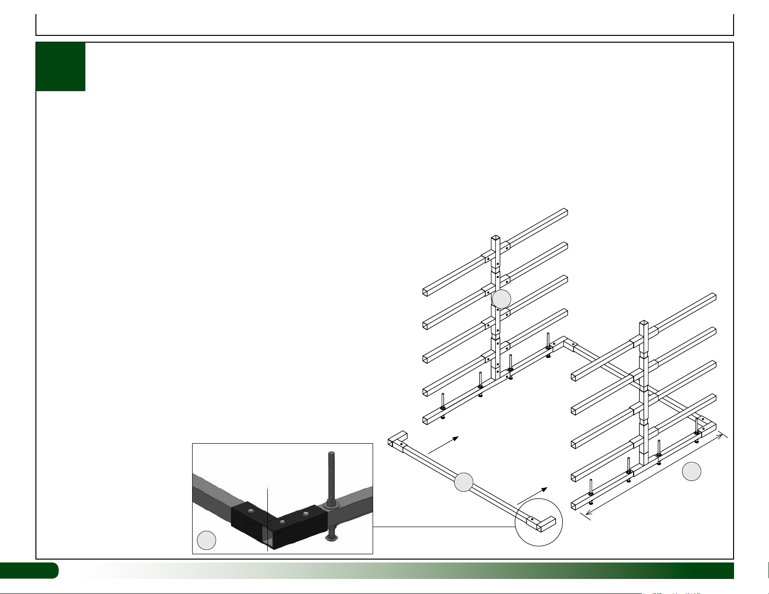
1. Gather the two (2) end support frames and two (2) assembled
base rails.
2. With assistance, assemble the frame as shown in the diagram.
Install base rails flush with the ends of the end support frames.
1
3. Check outside-to-outside dimensions of the assembled base.
Length at 51 1/2"; width at 55 3/4".
NOTE: If the dimensions are incorrect for the assembled frame,
verify that you have installed the base rails flush with the ends of
the end support base tubes. Also verify that the length of each
assembled base rail is 51 1/2".
4. Take an outer frame tube and slide it onto the support arms of
the end support frames as shown. Assemble main frame from the
bottom and work toward the top.
Install so tube and
2-way fitting are flush.
2
12
12
3
2
111628M Revision date: 09.25.18
55 3/4"
Page 13
ASSEMBLE MAIN FRAME: Assemble Frame—continued
1
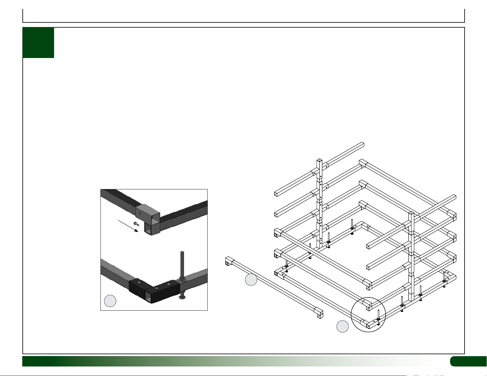
5. Secure the tube to the support arms of each end support
frame. See insert below.
6. Continue adding outer frame tubes until the main frame is
assembled.
7. Verify that all Tek screws are installed to secure fittings and
support tubes.
Install Tek screw through fitting and into support
arm. Install so support arm is flush to the outside
of the 2-way fitting.
Assembly Instructions
5
Revision date: 09.25.18 111628M
S15P027
4
5
13
Page 14

ASSEMBLE MAIN FRAME: Assemble Frame—continued
1
8. Next, install all 111628MC corner braces.
NOTE: These braces include pre-drilled mounting holes
that mirror the spacing of the individual levels. If the holes
don't match the spacing of the shelves, flip the brace endfor-end. Position the holes spaced closest together at the
bottom. Use the diagram in the Quick Start section to verify
spacing of shelves if needed.
9. Continue with the assembly of the fodder channels.
Tek
Screw
10" between
support arms
Assembly Instructions
111628MC
Corner
Brace
14
14
Tek
Screw
base & arm
Corner brace installed flush
with bottom of frame.
8 1/4"
between
ATTENTION: Install corner braces flush to the bottom of the main
frame. Measure to ensure that the space between the different levels is
as shown in the diagrams. Lift or press down to adjust the free end of
each support arm as needed before you attach the corner brace.
111628M Revision date: 09.25.18
Page 15

ASSEMBLE ALL 6' FODDER CHANNELS: 111582Z6
2
Complete these steps to prepare the 111030 end caps:
Rounded
Tab at
the Top
Required parts:
• 111030 End Cap (plain)
• 9/32" Drill Bit and Drill
Top Edge of End Cap
ATTENTION: Cover the
vice jaws or use material
to protect the end cap.
Assembly Instructions
111029 End Cap
ATTENTION: Complete this procedure for the 111030
plain end caps only. Do not drill holes in the 111029
end caps, which have an outlet.
1. Gently clamp the 111030 end cap in a vice or
similar device with the top, rounded edge up.
3. Using a drill and a 9/32" bit, carefully drill a
hole in the top lip of the 111030 end cap.
Revision date: 09.25.18 111628M
2. Locate the middle of the end cap lip and mark
the position using a pencil.
4. Remove the loose end cap material from the
drilled hole.
NOTE: Center mark on top lip is shown.
111030 End Cap
5. Repeat the steps to drill a hole in center of all
remaining 111030 end caps. Do not drill the
111029 end caps.
15
Page 16

Assembly Instructions
ASSEMBLE ALL 6' FODDER CHANNELS: 111582Z6
2
Complete these steps:
1. Place one 6' channel (111582Z6) on a flat surface for assembly. Cover the
assembly surface if needed to protect it from the adhesive.
2. Attach the plain end cap (drilled hole–111030) to one end of the 6'
channel. Coat all edges of the channel end with adhesive before installing
the cap. Cut nozzle tip at a 45° angle and just enough to allow the
adhesive to flow. A thin, continuous bead is all that is required.
3. Move to the other end of the channel and install the 111029 end cap (with
outlet). Coat all edges of the channel end with adhesive before installing
the cap.
4. Repeat Steps 1-3 for all remaining 6' channels.
5. Once all end caps are in place, carefully flip over one channel so the
bottom is facing up and the open top is down.
6. Take the adhesive and secure the end caps to the 6' channel. Photos
show securing the end cap with an outlet. Secure the plain end caps in the
same manner.
Required parts:
• 111029 End Cap (w/outlet) and 111030 End Cap (plain);
111582Z6 GT80 NFT Channels @ 6' long (each)
• 112509 Instant Adhesive
A
111582Z6 Channel (6')
111030
C
111029
E
bottom
B
D
F
Apply adhesive in a well-ventilated area. Read the 112509 adhesive
container information for additional precautions.
NOTE: Apply the adhesive to the outside of the channel assembly. Seal
all edges and seams of the end caps to prevent leaks. Apply the adhesive
to the inside of the channel only as needed to repair leaks. Verify that
surfaces are dry before applying additional adhesive to seal end caps.
7. Repeat for all remaining 6' fodder channels.
8. Allow the adhesive to dry before moving the channels or testing the
system. See the note to the right to test channels for leaks.
NOTE: Read the instructions on the adhesive container for recommended
drying times.
9. Continue with the assembly of the drain manifold.
16
16
ATTENTION: Coat the seams evenly
with a thick layer of adhesive to coat
all gaps. Once the adhesive has dried
according to the directions, fill channel
with water, set on a level, dry surface,
and check for leaks. Reseal if necessary.
When checking for leaks, slide a 90°
elbow onto the outlet end cap and turn
the open end of the elbow to the 12
o'clock position, and fill the channel.
Fill with water and
check for leaks.
GLUE
DO NOT GLUE ELBOW TO THE END CAP!
111628M Revision date: 09.25.18
Page 17

3
Assembly Instructions
ASSEMBLE THE DRAIN MANIFOLD
Required parts:
• 111560 2" PVC Pipe, WF6717 Slip Caps, and 111696
Double Hub (Cross Fitting)
• 111906 1" Sammys and 111907 Conduit Hangers
DRAIN MANIFOLD –
CENTER STACK
• FAK26 Threaded Rods and FALB04B Nuts
• 113372 Primer and WF6990 PVC Cement
Complete these steps:
1. Cut 8 horizontal tubes at 24" each. Use the 2" (111560) PVC.
2. Clean the ends of the PVC tubes to remove any loose material.
3. Mark the hole locations on each 24" tube and drill the holes for the drain
elbows of the channels. Use a 1 3/8" hole saw bit and a drill. (If possible,
drill the holes in the PVC tube using a drill press for accuracy.) Remove
loose material from around the holes and from inside each tube.
24"
Center Line
10 1/2"
4. After cleaning each 24" tube, attach the WF6717 slip cap to the end of the
tube as shown. DO NOT CEMENT THE CAPS TO THE TUBES. Caps
must remain free for cleaning of the tubes. Set these tubes aside for
later assembly of the drain manifold.
8"
For best results, use a step bit if
available to drill the holes in the pvc
tubing.
STEP 3
TOP
111696
Cross Fitting
Length
of each
tube: 8"
111696
Cross Fitting
111696
Cross Fitting
WF6717 Slip Cap–
Do not cement.
5. Using the 111560 2" PVC pipe, cut three (3) pieces at 8".
6. Take the 111696 cross fittings and 8" tubes and assemble the center stack
of the drain manifold as shown. Use PVC primer and cement to attach
the vertical 8" tubes to the cross fittings. Assemble on a flat surface for
best results and to keep the fittings aligned.
Revision date: 09.25.18 111628M
8"
BOTTOM
NOTE: Cement all 8" PVC sections to
the 111696 Cross Fittings using primer
and pvc cement.
111696
Cross Fitting
17
Page 18

Assembly Instructions
ASSEMBLE THE DRAIN MANIFOLD — continued
3
7. Once the PVC cement sets, take the center stack and attach it to the drain end of the assembled frame using the 111906 Sammys, 111907 conduit
hangers, 3/8" threaded rods, and 3/8" nuts. Tighten hangers just enough to hold stack in place. Stack will be adjusted (up or down) once the horizontal
drain tubes are installed. Do not cut the 12" threaded rods for this end. These can remain 12" long. The lower mounting stud and hanger can be
installed too. It is not shown; see call out below. It is used to secure the lower end of the manifold when the final short pipe section is added.
For best results, install the 111906 Sammys through
the 4-way fitting and into the vertical support tube. See
the photo to the right.
18
18
ATTENTION: Drill the mounting hole in
the 111907 hanger bracket to 7/16" if
needed to accept the 3/8" threaded rod.
Exercise caution. Clamp the hanger
bracket in a vice before drilling.
Nut used to lock rod to mounting stud.
FALB04B
Nut
Drilll mounting hole in bracket to 7/16" if
needed to accept the 3/8" threaded rod.
FAK26
Threaded Rod
111907
Hanger
Diagram to the left shows how to
assemble each mounting bracket.
The 111906 Sammys are first
installed using a 5/8" nut driver or
socket. After securing each FAK26
threaded rod to a 111907 hanger,
the assembly is then threaded into
the 111906 Sammy and locked into
place with the FALB04B 3/8" nut.
111628M Revision date: 09.25.18
Page 19

ASSEMBLE THE DRAIN MANIFOLD — continued
3
8. Next, take the prepared 24" tubes with the caps and verify
that each cap is installed at the end of the tube closest to
the first drain hole.
9. Attach the tubes to the manifold stack. Coat outside of
tube end and inside of cross fitting with PVC primer and
cement and insert end into an open socket of cross fitting.
NOTE: Verify that drain holes of each tube are pointing
up. If the 6' fodder channels are resting on the fodder
frame, slide these back and away from the drain manifold
tubes until the PVC cement has dried.
Adjust tubes as needed before PVC cement sets up.
Also, before cement sets, slightly lift cap end of tube to
create a minor slope toward center stack. This will help
water drain from horizontal tubes.
10. Repeat until all horizontal drain tubes are installed.
Assembly Instructions
Drain manifold complete with all horizontal tubes installed.
Revision date: 09.25.18 111628M
Slightly lift the end of each
tube during installation
before the cement sets so
tubes slope to the center
tube.
19
Page 20

ASSEMBLE THE DRAIN MANIFOLD — continued
3
11. Place the 6' channels on the frame if needed and adjust the
entire drain manifold (up or down) to allow the channel drain
elbows to be placed inside the horizontal tubes. Tighten the
hanger bolts.
NOTE: Do not set the manifold too high. Verify that the end
of each fodder channel remains on the horizontal tubes of
the metal fodder frame. No weight from the fodder channels
should rest on the drain manifold horizontal tubes.
12. If this has not been done yet, assemble and install the
remaining 111906 Sammy, 111907 hanger, 3/8" threaded rod,
and 3/8" hardware to secure the lower tube to the main frame.
13. Install the upper tube and cap and the lower tube, drain
end elbow and extension to complete the drain manifold.
Add primer and cement and secure tubes to cross
fittings. FOLLOW ASSEMBLY INSTRUCTIONS ON PVC
CONTAINERS!
NOTE: Angle and use of the lower 90° elbow depends on
application. Extension tube is constructed using leftover PVC
tube. Additional tubing can be purchased locally, or call your
sales representative for additional information. Install this last
and after the supply manifold is assembled and attached to
the frame.
Assembly Instructions
Upper Tube with Cap —
Do not cement cap to
tube. Cement tube to
cross fitting using primer
and pvc cement.
14. Continue with the installation of the supply manifold.
Lower Tube with 90° Elbow — Length of
vertical tube depends on application and
height of drain manifold on the frame. Use of
extension tube depends on location of drain
and design of the drain system.
Elbow should rest on ground to help stabilize
the drain manifold.
20
20
Step 12: Install final
assembled hanger.
111628M Revision date: 09.25.18
Page 21

Assembly Instructions
INSTALL THE SUPPLY MANIFOLD
4
Complete these steps to attach the supply manifold to the frame:
1. Move to the supply end of the frame and attach one (1) 106808
pipe hanger to the frame in the locations shown. Secure each
hanger to the frame using one FA4472B Tek screw and the 100442
magnetic driver. Circles identify hanger position on frame.
Required parts:
• (8) 112305 (18" Supply Tube w/ Micro Valve)
• (8) 112306 (28" Supply Tube w/ Micro Valve)
• (1) 112527 (3/4" PVC Supply Manifold)
• (3) 106808 (3/4" Pipe Hangers)
• (2) FA4472B Tek Screws and 100442 Nut-Setter (5/16")
In the locations
shown on the
diagram (lower-left),
predrill a mounting
hole using an
FA4472B Tek screw.
Slide the 106808
hanger over the Tek
screw and attach to
the frame.
FA4472B Tek
Screw
100442
Driver
106808 Pipe Hanger
Revision date: 09.25.18 111628M
Before the screw
is tight, align the
hanger on the frame
as shown to prepare
for the manifold
installation. Tighten
the screw.
Repeat to install all
remaining 106808
pipe hangers.
21
Page 22

Assembly Instructions
INSTALL THE SUPPLY MANIFOLD — continued
4
2. After attaching all pipe hangers to the frame, take the 112527 3/4"
PVC supply manifold and position it against the installed hangers.
NOTE: This procedure shows attaching the manifold to the frame
before adding the supply tube assemblies. These tube assemblies
can be installed before you secure the manifold to the frame. Steps
3 and 4 describe the installation of the supply tubes.
Supply Manifold
STAND-ALONE UNIT
ONLY—If you are
attaching the main
water line at the
bottom, slide manifold
up during installation
to provide the needed
clearance, or trim to
length as needed.
ATTENTION: Handle the supply manifold carefully during installation to
prevent damage to the supply tube fittings! These can break if handled
improperly! Actual manifold and system may differ from what is shown.
22
22
Trim top of manifold
if desired and cement
the WF2990 slip cap in
place with PVC primer
and cement.
111628M Revision date: 09.25.18
Page 23

4
Assembly Instructions
INSTALL THE SUPPLY MANIFOLD — continued
ATTENTION: Handle the supply manifold carefully during installation to prevent
damage to the supply tube fittings! These can break if handled improperly!
Gently grip the manifold near a hanger and
push toward the frame to lock the manifold in
the hanger. Repeat this at each hanger.
Revision date: 09.25.18 111628M
Sample fodder system is shown. Actual system may differ.
23
Page 24

Assembly Instructions
INSTALL THE SUPPLY MANIFOLD — continued
4
3. Next, locate the supply tubes with micro valves. There are two
different lengths for this fodder system–112305 (18") & 112306
(28").
4. Install two (2) short tubes (112305) and two (2) long tubes
(112306) at each level as shown.
ATTENTION: FITTINGS ON MANIFOLD CAN BREAK! DO
NOT FORCE THE TUBES ONTO THE MANIFOLD FITTINGS!
WET THE END OF EACH TUBE BEFORE INSTALLATION AND
GENTLY SLIDE IT EVENLY OVER THE FITTING.
112305
Wet the end
of the supply
tube.
Gently slide
it onto the
fitting.
112306
24
24
Repeat for
all remaining
supply tubes.
111628M Revision date: 09.25.18
Page 25

Assembly Instructions
SET THE PROPER SLOPE (3"- 4") OF THE FODDER FRAME
5
The 111628M fodder frame is equipped with three (3) sets of levelers—one set at each of the vertical frame assemblies.
The following steps assume the fodder system is setting on a level surface. If the system is on a sloped concrete pad
for example, adjust the following steps as needed to achieve the 3"- 4" slope. Depending on the slope of the floor, it is
possible that the levelers will be used to simply level the frame from side-to-side. See Fig. 1.
ATTENTION: Too great a slope can cause the seeds to wash toward the drain end of the channels. Levelers are
designed to adjust for minor or slight variations in the site. For safety, a level site is required! When adjusted properly,
all levelers must touch the floor to stabilize the frame. Tighten the locking nuts to maintain the adjustment and to lock the
levelers to the base rail.
Depending on the site, it may be necessary to remove the four (4) leveler bolts at the drain end (or low end) of
the frame to achieve a 3" to 4" recommended slope.
Figure 1
To ensure that water flows through and properly drains from the fodder channels, a 3"- 4" slope toward the
drain end of the system is required. Frame must also be level from side-to-side when viewed from the end.
Photo shows the levelers as attached to the base
rail of the end frame. Actual bolt may differ.
Drain End of the Frame
Finished Grade
Revision date: 09.25.18 111628M
Adjust to
set a 3"-4"
slope to
drain end.
Finished Grade
Adjust bolt to
lowest setting
and level
frame.
25
Page 26

Assembly Instructions
6
Complete these steps:
1. Verify that the lower drain tube of the drain manifold is positioned to direct water to the required floor drain.
2. Check all supply tubes with micro valves and verify that the 3" extension tube is inserted into the drilled hole of each 111030 end cap. See page 16.
3. Attach the main water supply line to the supply manifold. Main supply line can be attached to the top or bottom of the supply manifold—single, stand-
alone fodder system only.
ATTENTION: Supply line must include the following additional customer-supplied components: timer, in-line pressure regulator, pressure gauge, on-off
solenoid, and water meter (optional). Additional plumbing fittings and electrical components are needed to connect the timer and solenoid and to connect
the supply line to the center stack of fodder supply manifold. Contact your sales representative with your list of the required fittings specific to your main
water supply line. See the diagram on Page 3.
4. After attaching the main water supply line, verify that the micro valve in the supply tube to each fodder channel is fully open and turn on the water.
5. Allow air to bleed from the system until water flows freely from each of the supply tubes.
6. Close all valves and inspect the supply manifold and supply tube assemblies for leaks. Occasionally micro valves may leak. Most seal after a few water
cycles. Twist the on/off knob back and forth to help seat the valve. Do not use pvc cement or other sealants when attempting to stop a leaky micro valve
in a supply tube. Doing so may damage the valve.
TEST SUPPLY MANIFOLD AND CHECK FOR LEAKS
7. If leaks are found in areas other than a micro valve, mark the leak location. Turn off the water, dry the fitting or end cap, and seal using pvc cement or
adhesive. Allow the area to dry according to the directions on the adhesive container, and recheck.
8. After checking the system for leaks, continue reading the information in the Quick Start section to get started growing fodder.
26
26
111628M Revision date: 09.25.18
Page 27

111628M
Full Frame
View
S15P027
111628M Quick Start Guide: Full Frame Assembly
S15P027
S15P048
111485
111485
111485
C
104627
104625
S15P048
111628A
104626
104625
1/2" X 5" CARRIAGE BOLT
- (2X) 1/2" WASHER
- (2X) 1/2" HEX NUT
104626
Revision date: 09.25.18 111628M
27
Page 28

111628M Quick Start Guide: End Frame Assembly
1
1
50"
111628MC
Corner Brace
S15P027
Tube
S15P048
Tube
"
27
8
1
"
21
4
27
21
"
8
1
"
4
104625
2-Way
Connector
111628A
Tube
111485 2-Way
Connector w/
Off-Set
104627
4-Way
Connector
104626
3-Way
Connector
10"
28
9
3
4
8"
"
3
"
1
4
1
8
4
10"
3
47
"
4
10"
"
111628M Revision date: 09.25.18
48"
Page 29

FIGURE 1: Assemble levelers
as shown.
111628B
111628M Quick Start Guide: Basic Assembly
ATTENTION: See Pages 7-9
for additional details.
104626
3-Way
Connector
111628A
FIGURE 2: Assemble base rails as shown. The 3-way connector
is loose at this point. Levelers should be finger-tight to allow for
adjustments once the system is assembled and in position.
FA4482B Tek
Screw
Mark the center
of connector.
FIGURE 3: Center the connector on the base rail and
secure using two (2) FA4482B Tek screws.
Revision date: 09.25.18 111628M
9-3/4" between
connectors.
FA4482B
Tek Screws
S15P081
8" between
connectors.
This level only.
Assembled Base Rail with Levelers
S15P027 S15P027
FA4482B
Tek Screws
111628A Base Rail
29
Page 30

ATTENTION: See Page 10
for additional details.
111628M Quick Start Guide: Basic Assembly
Open end of
connector
S15P048
Base Rail
Length 51 1/2"
outside-to-outside
Open end of
connector
ATTENTION: See Page 11
for additional details.
30
Open end of
connector
Length 51 1/2"
outside-to-outside
S15P048
Base Rail
Open end of
connector
Fig. A: Pre-mark tube for easier
assembly.
Approximate End of Tube
Fig. B: Minor adjustments to the
connector position will be require
when setting length.
111628M Revision date: 09.25.18
Page 31

111628M Quick Start Guide: Basic Assembly
ATTENTION: See Page 12
for additional details.
Install so tube and
2-way fitting are flush.
Revision date: 09.25.18 111628M
31
Page 32

ATTENTION: See Page 13
for additional details.
111628M Quick Start Guide: Basic Assembly
S15P027
Install Tek screw through fitting and into
support arm. Install so support arm is flush
to the outside of the 2-way fitting.
32
111628M Revision date: 09.25.18
Page 33

ATTENTION: See Page 14
for additional details.
111628M Quick Start Guide: Basic Assembly
111628MC
Corner Brace
Tek
Screw
10" between
support arms
Revision date: 09.25.18 111628M
111628MC
Corner Brace
Tek
Screw
8 1/4"
between
base & arm
Corner brace installed flush
with bottom of frame.
33
Page 34

Quick Start Guide: Additional Drain Manifold Photos
Photos on this page show the assembled drain manifold as attached to the frame. (Manifold can be assembled on a flat surface and
then attached to the frame to allow easier adjustment of the manifold height on the frame if desired.) Dry fit all manifold components
before you secure the horizontal tubes to the 111696 cross fittings only. Coat the outside of one end of a tube and the inside of
fitting with PVC primer and cement. Slide tube into the 111696 fitting. Gently lift the open end of the tube to create a slight slope
toward the center stack. Allow the cement to set and release the tube. Repeat for all remaining horizontal tubes. Install the slip
caps. Do not secure the slip caps to the ends of the horizontal tubes. These must remain free to remove so the horizontal
tubes can be cleaned.
34
111628M Revision date: 09.25.18
Page 35

Quick Start Guide: Additional Drain Manifold Photos & Diagram
ATTENTION: See Pages 17-20
for additional details.
On-Center Hole Spacing: Use a
1-3/8" hole saw bit to drill holes in
PVC tubing for channel drain elbows.
8"10 1/2"
For best results, use a step bit if
available to drill the holes in the pvc
tubing.
Drain Manifold
Minimum 8"
Tube
Revision date: 09.25.18 111628M
111696
Fitting
WF6717
Slip Cap–No
Cement
WF1576
Elbow
NOTE: Do not cement any WF6717 slip cap to tubes.
8"
Tube
24" Tube
Length depends on how customer
plans to drain the system.
35
Page 36

Slide the 106808
hanger onto the Tek
screw and attach to
the frame.
Hanger locations
are circled in the
diagram below.
Supply Manifold
Quick Start Guide: Supply Manifold Photo & Diagrams
ATTENTION: See Pages 21-24
for additional details.
106808 Pipe Hanger
1. Attach hangers and manifold to frame.
36
2. Attach supply tubes to manifold. 3. Slide tube ends into 111030 end caps.
111628M Revision date: 09.25.18
Page 37

Quick Start Guide: Supply Manifold Photos
Photo shows the supply manifold and attached supply tubes.
Top of manifold is sealed with a WF2990 slip cap cemented
in place using PVC primer and cement. Water supply line is
attached to bottom of manifold.
Photo above shows the supply tube and micro valve as installed in the
111030 end cap. View shows the inside of a fodder channel.
*Actual fodder system may differ from what is shown in these sample photos.
Revision date: 09.25.18 111628M
Photos shows a section of a working fodder system. The supply manifold
and supply tubes are shown. Actual fodder system may differ.
37
Page 38

Quick Start Guide: Additional Channel Photos & Maintenance
INSTALL THE 111303 SEED SCREEN
The 111303 seed screen is designed to help prevent seeds from
washing into the drain manifold and floor drain. Before spreading
the soaked seed into each channel, insert a screen into the outlet
of each fodder channel as shown. Screen is held in place by
friction and is not threaded into the outlet.
Remove the screen before you harvest the fodder to prevent
loosing it. Screen can be cleaned with the same bleach solution
used to clean the fodder channels.
Slide the screen back into the channel once it has been cleaned.
111303 Seed Screen
Basic Maintenance
The fodder system requires regular maintenance and cleaning. The duration between the maintenance and cleaning sessions, however, depends on how
and where the system is used and what seeds are grown. The only way to determine a regular maintenance and cleaning schedule is to closely monitor
your system once it is fully functioning. A clean fodder system increases fodder production and reduces loss due to mold and other harmful biological and
environmental factors.
Below are a few suggestions to help maintain and clean the fodder system:
• Check all fittings and channels to ensure there are no leaks. Repair or replace damaged parts immediately. Seal all leaks when found.
• Clean and disinfect the fodder channels after each harvest. System is designed so channels can be removed and cleaned. Use a 10:1 mixture (water/
bleach) to disinfect the channels when cleaning. Be sure to rinse thoroughly to remove the cleaning solution before using the channels.
• Periodically remove the ends of the horizontal drain manifold tubes and clean the entire drain manifold using the bleach solution mentioned above to
prevent unwanted growth of loose seeds, bacteria, fungus, and mold. The entire drain manifold should be disinfected regularly to prevent odor.
38
111628M Revision date: 09.25.18
Page 39

111628M Quick Start Guide: General Information
General Startup
Many factors must be considered before you begin growing fodder in your
new system. One of the best sources of information is the internet. Spend
as much time as needed to research how you want to get the most out of
your system. Each growing situation and fodder use is unique to the user. To
prevent frustration and wasted time, a few hours spent on the internet can
save you days or weeks in the field trying to achieve acceptable results.
Remember: To achieve the results specific to your fodder needs, you must
experiment using your fodder system and record the results for reference.
This will help you to better understand how the system works, what
conditions are required to achieve maximum production, and how to adapt
and react to changes when these occur.
Here are a few items to consider before you get started:
• What animals (and how many) will eat the fodder?
• How often will you feed fodder to your animals?
• Where will you set the fodder system and what are the environmental
conditions of that location?
• Is water and electricity available for the fodder system?
• Is a floor drain near where the fodder system will be placed?
• Is the space large enough to allow easy harvest of the fodder and
maintenance of the system?
• Is there enough light (natural or artificial) to help the fodder grow?
Mold Growth
Controlling mold growth is important if you want to produce healthy and safe
fodder. Here's one way to help keep your system mold-free:
1. Purchase bulk hydrogen peroxide (30%) and dilute with water to a 15%
solution. Store and handle as instructed on the container!
2. Purchase an injector (see photo below) and connect it to the main water
supply line to the fodder system.
3. Set the injector to inject the 15% hydrogen peroxide solution into the
water system. Use an injector setting of 1:100 to begin.
IMPORTANT: Mold
grows best when heat
and humidity increase.
To inhibit mold growth,
maintain a cool, dry
growing environment
for the fodder. Frame
shown may differ from
actual frame.
• Will you be able to clean and maintain the system as required in the
location where the fodder system will be placed?
• What type of seed or grain will you grow?
• Have you found a supplier for your seed/grain?
• Will clean seed/grain be used, or do you plan to clean these yourself?
• How will you store the seed to prevent loss to rodents and pests?
• How will you transport the fodder from the system to the animals?
• Do you have access to products and information to help prevent mold
and fungus growth should these occur?
Revision date: 09.25.18 111628M
4. Monitor fodder growth and hydrogen peroxide use and adjust the injector
as needed to achieve the best results.
NOTE: Although more time-consuming, a hydrogen peroxide solution can
also be applied using a hand or portable pump sprayer if an injector is not
used. For this method, use a 1% to 3% hydrogen peroxide solution.
Inspect the sprouts and fodder for signs of mold and spray as needed.
Clean all channels thoroughly after harvest and before planting.
39
Page 40

111628M Quick Start Guide: Growing Tips
General Growing Tips
Despite the factors that must be addressed before you begin using your
fodder system, these general tips will help you get started:
• Water Quality: Clean water is a must. If you can’t drink it, don’t use it. If
you are not sure about the water quality, have it tested.
• Water Temperature: Keep the water temperature constant and in the
range suitable for the seed or grain you are using.
• Quality of the Seed or Grain: While it may cost slightly more, good
quality, clean grain or seed will save time. You won’t have to clean the
grain, or worry about foreign objects growing in the fodder that might
pose a danger to your animals if eaten.
• Climate Control: A properly maintained environment is a must. Ensure
you have controls in place to automatically control temperature and
humidity. Additionally, do not rely solely on automatic equipment;
ensure you are physically monitoring the environment daily and make
adjustments if needed.
• Keep the System Clean: Follow the cleaning guidelines presented in
this guide.
General Guidelines to Promote Optimal Growth
Water Temperature 60° F (minimum) to 75° F (maximum)
pH Level 6.2 - 6.4 (range)
Humidity 40% to 80% (Best in most cases is 60%.)
Ideal Temperature Range 63° F to 75° F
Design Yield Test Using Barley Seed*
The 111628M FodderPro 2.0 Micro System is designed to harvest two (2)
6' GT80 premium channels per day. Trial was conducted using barley
grain. (It is expected that results will vary when different seed is used.)
Consult the information that follows to help determine how best to use your
system to produce the fodder you will need.
1. Soak the Seed: Seeds were soaked overnight before they were added
to the channels and spread to the required uniform depth. For best
results, maximum soak time is 24 hours; minimum soak time is 12
hours. Begin with 4.25 to 4.5 pounds of barley seed per channel.
(Note: Seed quality and growing conditions can affect germination rates,
yield results, and amount of seed required. Adjust quantity as needed.)
2. Preparation: To begin, seed was divided evenly and spread in two (2)
of the channels at a depth of approximately 1/4” with a 1–1 ½” space
between the seedbed and the ends of the channel. This allows room
for expansion as the seeds swell from the water and ultimate sprouting
of the seed mat. It's best to seed the channels all on one level to more
easily track.
After seeding the channels, turn on the water to the first level and begin
the cycling process. Monitor the channels to ensure the valves are
adjusted properly and to ensure the seed does not dry out. Adjust the
timer (number of cycles and cycle duration) and valves as needed.
3. Calculations: Preliminary trials produced approximately 5 lbs. of fodder
per one (1) foot of channel. This equals about 30 pounds of fodder per
6' channel. Estimated production can be up to 60 pounds of fodder per
two (2) channels per day. (Individual results may vary.)
4. Estimated Capacity: Using a typical diet of 2% of the animal’s body
weight for fodder, estimated feed capacities for the 111628M FodderPro
2.0 Micro System are shown in the table below.
40
Estimated Feeding Capacity
ANIMAL BODY WEIGHT DAILY FEEDING CAPACITY (# OF HEAD)
1,400 lbs 1 - 2
800 lbs 3 - 4
500 lbs 5 - 6
200 lbs 14 - 15
Poultry 575 - 625
*INDIVIDUAL RESULTS MAY VARY.
111628M Revision date: 09.25.18
Page 41

111628M Quick Start Guide: Getting Started
The photos on this page show fodder at various stages of growth. The
design of the fodder system shown in these photos differs from the 111628M
FodderPro 2.0 Micro System. Photos are included for reference only.
Use the following steps as a basic guide to get started. These are general
steps; additional steps specific to your planned fodder production may be
necessary.
1. Assemble the fodder system, connect the main water supply, set the
channels in place on the frame, and test the system. Timer, regulator,
solenoid, and pressure gauge must be installed.
2. Determine what seed to grow and purchase the seed. Soak the seeds in
the soaker bags and buckets for the required time.
3. Using the seed spreader, spread the seed to a uniform depth. Consult
the Design Yield Test information on the previous page for the
2-channel rotation calculations.
4. Turn on the timer to supply water to the seeded fodder channels.
NOTE: The water flow rate and the control of the water depends on
many different factors and is accomplished by operating the in-line
valves and setting the number of cycles and cycle duration, which are
controlled by the timer. Careful monitoring of the fodder system for the
first few fodder production cycles is strongly recommended. During
this time you can determine when water is needed and how much
water is needed. Consult the documentation included with the timer to
properly set and maintain the timer. Consult the services of a qualified
electrician to install the timer and connect the pump to the timer. Record
all settings, temperature, and results to use as a reference for future
adjustments.
Photos above show the 107651 bucket and the 111041 soaker bag. Add seed to the
bag, set inside the bucket, and add water to cover all seed.
5. Adjust water flow using the in-line valves. Monitor the flow so that seeds
do not wash to the screen end of the channels. As more level of the
system are put into production, water valves will need adjusting. Once
all levels are in production and the valves have been set, additional
adjustments should be minor.
6. Set the timer to control when water is supplied to the channels.
7. Monitor the system and inspect the seeds to ensure that mold is not
present. Consult internet data specific to your type of fodder.
8. Continue to soak seeds, load fodder channels, and harvest fodder
according to your fodder production plan and schedule.
Revision date: 09.25.18 111628M
111822
Photos above show the seed as spread
in a fodder channel. Photo to the left
shows the 111822 seed spreader used
to spread the seed in a channel. Tabs
are designed to ride on the edges of the
channel. Tilt the spreader as needed to
achieve the desired seed depth.
41
Page 42

111628M Quick Start Guide: Getting Started–continued
Photo shows the seed as it grows in the fodder channel.
Close-up photos showing seed growth.
Photo shows the seed at different stages of growth.
Fodder is shown ready to harvest. Remove the fodder from the channel and
feed the entire mat to the animals. Clean the channel, reseed, and repeat the
process.
42
111628M Revision date: 09.25.18
Page 43

Page Reserved for Customer Notes
Revision date: 09.25.18 111628M
43
 Loading...