

Page 1
OWNER’S/
OPERATOR’S
MANUAL
MODEL NO.
720
CAUTION
For Safe Operation
Read Rules And
Instructions Carefully
SINO LEEINGLES, PIDAAYUDA
A AIGUIEN QUE SI LO LEA
PARA QUE LE TRADUZCA LAS
MEDIDAS DE SEGURIDAD.
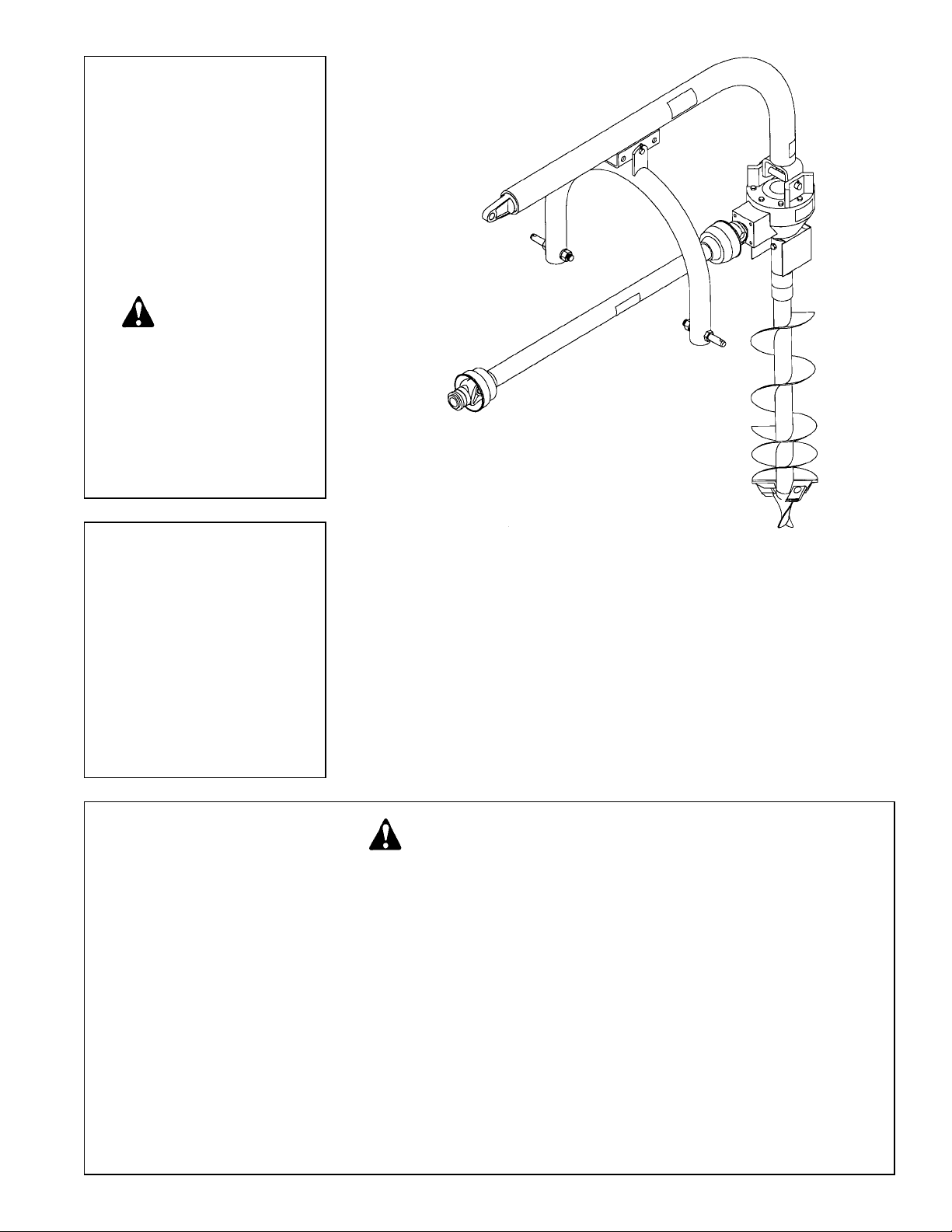
HEAVY DUTY 3-PT. MOUNTED
POST HOLE DIGGER
Safety Instructions Assembly & Mounting
Tractor Preparation Maintenance
Operating Instructions Repair Parts
STATEMENT
OF POLICY
It is the policy of Farm
Star to improve its products
where it is possible and practical
to do so. Farm Star
reserves the right to make
changes or improvements in
design and construction at any
time, without incurring the obligation to make these changes on
previously manufactured units.
CAUTION
THE FOLLOWING SAFETY PRECAUTIONS SHOULD BE THOROUGHLY UNDERSTOOD
BEFORE ATTEMPTING TO BEGIN ASSEMBLING THIS MACHINE
1. Select an area for assembly that is clean and free of any
debris which might cause persons working on the
assembly to trip.
2. Do not lift heavy parts or assemblies. Use crane, jack,
tackle, fork trucks or other mechanical devices.
3. Preview the assembly instructions in your operator’s
manual before proceeding further.
4. If the assembly instructions call for parts or assemblies to
be blocked up, use only blocking material that is in good
condition and is capable of handling the weight of the
assembly to be blocked. Also insure that the blocking
material is on a clean, dry surface.
5. Never put hands, or any part of body, under blocked up
assemblies if at all possible.
6. After completing assembly, thoroughly inspect the
machine to be sure that all nuts, bolts, hydraulic fittings
or any other fastened assemblies have been thoroughly
tightened.
7. Before operating the machine, thoroughly read the
operation section of your operator’s manual.
8. Before operating, read the maintenance section of your
operator’s manual to be sure that any parts requiring
lubrication, such as gearboxes, are full, to avoid any
possible damage.
9. Before operating equipment – If you have any
questions regarding the proper assembly or
operation, contact your dealer or representative.
Page 2

T o the Owner/Operator/Dealer
All implements with moving parts are potentially hazardous. There is no substitute for a cautious, safe-minded operator who recognizes the potential hazards and follows reasonable safety practices. The manufacturer has designed this
implement to be used with all its safety equipment properly attached to minimize the chance of accidents.
BEFORE YOU START!!
Read the safety messages on the implement and shown in your manual.
Observe the rules of safety and common sense!
THIS SAFETY ALERT SYMBOL IDENTIFIES IMPORTANT
SAFETY WARNING MESSAGES. CAREFULL YREAD EACH
WARNING MESSAGE THAT FOLLOWS. FAILURE TO
UNDERSTAND AND OBEY A SAFETY WARNING, OR
THIS SYMBOL MEANS
– A TTENTION!
– BECOME ALERT!
– YOUR SAFETY IS INVOLVED!
RECOGNIZE A SAFETY HAZARD, COULD RESULT IN AN
INJURY OR DEATH TO YOU OR OTHERS AROUND YOU.
THE OPERATOR IS ULTIMATELY RESPONSIBLE FOR THE
SAFETY OF HIMSELF, AS WELL AS OTHERS, IN THE
OPERATING AREA OF THE TRACTOR AND ATTACHED
EQUIPMENT.
UNDERSTAND SIGNAL WORDS
Note the use of the signal words DANGER, WARNING
and CAUTION with the safety messages. The
appropriate signal word for each has been selected
using the following guidelines:
DANGER: Indicates an imminently hazardous situation
that, if not avoided, will result in death or serious injury.
This signal word is to be limited to the most extreme
situations typically for machine components which, for
functional purposes, cannot be guarded.
If you have questions not answered in this manual or require additional copies or the manual is damaged, please
contact your dealer or the manufacturer directly.
WARNING: Indicates a potentially hazardous situation that, if not avoided, could result in death
or serious injury, and includes hazards that are
exposed when guards are removed. It may also
be used to alert against unsafe practices.
CAUTION: Indicates a potentially hazardous situation that, if not avoided, may result in minor or
moderate injury. It may also be used to alert
against unsafe practices.
IMPORTANT SAFETY INFORMATION!
Working with unfamiliar equipment can lead to careless injuries. Read this manual, and the manual for your tractor,
before assembly or operating, to acquaint yourself with the machines. It is the implement owner’s responsibility, if this
machine is used by any person other than yourself, is loaned or rented, to make certain that the operator, prior to
operating:
1. Reads and understands the operator’s manuals.
2. Is instructed in safe and proper use.
The use of this equipment is subject to certain hazards which cannot be protected against by mechanical
means or product design. All operators of this equipment must read and understand this entire manual, paying
particular attention to safety and operating instructions, prior to using. If there is something in this manual you
do not understand, ask your supervisor, or your dealer, to explain it to you.
Page 3

2
SAFETY INSTRUCTIONS (continued)
Safety of the operator is one of the main concerns in designing and developing a new piece of equipment.
Designers and manufacturers build in as many safety features as possible. However, every year many
accidents occur which could have been avoided by a few seconds of thought and a more careful approach to
handling equipment. You, the operator, can avoid many accidents by observing the following precautions in
this section. To avoid personal injury, study the following precautions and insist those working with you, or for
you, follow them.
In order to provide a better view, certain photographs or illustrations in this manual may show an assembly
with a safety shield removed. However, equipment should never be operated in this condition. Keep all shields
in place. If shield removal becomes necessary for repairs, replace the shield prior to use.
To prevent injury or death, use a tractor equipped with a Roll-Over Protective System (ROPS). Do not paint
over, remove or deface any safety signs or warning signs on your equipment. Observe all safety signs and
practice the instruction on them.
Never exceed the limits of a piece of machinery. If its ability to do a job, or to do so safely, is in question -
DON’T TRY IT.
Do not modify the equipment in any way. Unauthorized modification may impair the function and/or safety and
could affect the life of the equipment.
In addition to the design and configuration of this implement, including Safety Signs and Safety Equipment,
hazard control and accident prevention are dependent upon the awareness, concern, prudence, and proper
training of personnel involved in the operation, transport, maintenance, and storage of the machine. Refer also
to Safety Messages and Operation Instructions in each of the appropriate sections of the Tractor and
Implement Manuals. Pay close attention to the Safety Signs affixed to the Tractor and the Implement.
Replace any CAUTION, WARNING, DANGER or instruction safety sign that is not readable or is missing.
Location of such safety signs is indicated in this booklet.
Never use alcoholic beverages or drugs which can hinder alertness or coordination while operating this
equipment. Consult your doctor about operating this machine while taking prescription medications.
Review the safety instructions with all users annually.
This equipment is dangerous to children and persons unfamiliar with its operation. The operator should be a
responsible adult familiar with farm machinery and trained in this equipment’s operations. Do not allow per-
sons to operate or assemble this unit until they have read this manual and have developed a thorough
understanding of the safety precautions and of how it works.
EQUIPMENT SAFETY GUIDELINES
Page 4
SAFETY INSTRUCTIONS (continued)
SAFETY SIGNS
Keep safety signs clean and legible at all times.
Replace safety signs that are missing or have become illegible.
Replaced parts that displayed a safety sign should also display the current sign.
Safety signs are available from your Distributor or Dealer Parts Department or the factory.
How to Install Safety Signs:
Be sure that the installation area is clean and dry. Be sure temperature is above 50˚F (10˚C).
Decide on the exact position before you remove the backing paper.
Remove the smallest portion of the split backing paper. Align the sign over the specified area and carefully
press the small portion with the exposed sticky backing in place.
Slowly peel back the remaining paper and carefully smooth the remaining portion of the sign in place. Small
air pockets can be pierced with a pin and smoothed out using the piece of sign backing paper.
SAFETY TRAINING
Safety is a primary concern in the design and manufacture of our products. Unfortunately , our efforts to provide
safe equipment can be wiped out by a single careless act of an operator. It is the operator’s responsibility to
read and understand ALL Safety and Operating instructions in the manual and to follow these. Accidents can
be avoided.
In addition to the design and configuration of equipment, hazard control and accident prevention are dependent upon the awareness, concern, prudence and proper training of personnel involved in the operation, transport, maintenance and storage of equipment.
Working with unfamiliar equipment can lead to careless injuries. Read this manual, and the manual for your
tractor, before assembly or operating, to acquaint yourself with the machines. It is the implement owner’s
responsibility, if this machine is used by any person other than yourself, is loaned or rented, to make certain
that the operator, prior to operating:
1. Reads and understands the operator’s manuals.
2. Is instructed in safe and proper use.
Know your controls and how to stop tractor, engine, and implement quickly in an emergency. Read this manual
and the one provided with your tractor.
Train all new personnel and review instructions frequently with existing workers. A person who has not read
and understood all operating and safety instructions is not qualified to operate the machine. An untrained
operator exposes himself and bystanders to possible serious injury or death.
Do not allow children to operate this machine.
3
Page 5
4
SAFETY INSTRUCTIONS (continued)
PREPARATION
Personal protection equipment including hard hat, safety glasses, safety shoes, and gloves are recommended
during assembly , installation, operation, adjustment, maintaining, repairing, removal, or moving the implement.
Do not allow long hair, loose fitting clothing or jewelry to be around moving parts.
PROLONGED EXPOSURE TO LOUD NOISE MAY CAUSE PERMANENT HEARING LOSS!
Tractors with or without implements attached can often be noisy enough to cause permanent, partial hearing
loss. We recommend that you wear hearing protection on a full-time basis if the noise in the Operator’s position exceeds 80db. Noise over 85db on a long-term basis can cause severe hearing loss. Noise over 90db
adjacent to the Operator over a long-term basis may cause permanent, total hearing loss. NOTE: Hearing loss
from loud noise (from tractors, chain saws, radios, and other such sources close to the ear) is cumulative over
a lifetime without hope of natural recovery.
This Post Hole Digger was designed for one-man operation from the tractor seat. It is the responsibility of the
operator to see that no one is within twenty-five feet (25’) of the digger when it is started. Do not operate the
digger with another person near, or in contact with, any part of the digger, PTO driveline, or auger. Serious
personal injury or death may result if any attempt is made to assist digger operation by hand.
Most accidents occur because of neglect or carelessness. Keep all helpers and bystanders twenty-five feet
(25’) from an operating digger. Only properly trained people should operate this machine. It is recommended
the tractor be equipped with a Rollover Protection System (ROPS) and a seat belt that is used. Always stop
the PTO, set brake, shut off the tractor engine, remove the tractor key, and allow auger to come to a complete
stop before dismounting tractor. Never leave equipment unattended with the tractor running.
All things with moving parts are potentially hazardous. There is no substitute for a cautious, safe-minded
operator who recognizes potential hazards and follows reasonable safety practices. The manufacturer has
designed this digger to be used with all its safety equipment properly attached, to minimize the chance of
accidents. Study this manual to make sure you have all safety equipment attached.
If a safety shield or guard is removed for any reason, it must be replaced before the machine is again operated.
Always use, and maintain in place, all power take off guards furnished with the tractor as well as the power
take off guards and shields furnished with the digger.
Clear area of stones, branches or other debris that might be thrown or entangled, causing injury or damage.
Operate only in daylight or good artificial light.
Make sure driveline spring-activated locking pin or balls operate freely and are seated firmly in tractor PTO
stub shaft groove.
Ensure that all safety shielding and safety signs are properly installed and in good condition.
OPERATIONAL SAFETY
Page 6

SAFETY INSTRUCTIONS (continued)
OPERATIONAL SAFETY (continued)
This digger is designed for use only on tractors with 540 RPM power take off.
When the use of hand tools is required to perform any part of assembly, installation, adjustment, maintaining,
repairing, removal, or moving the digger, be sure the tools used are designed and recommended by the tool
manufacturer for that specific task.
Never place yourself between the tractor and digger while implement is in operation.
Do not walk or work under a raised digger or attachment unless it is securely blocked or held in position. Do
not depend on the tractor hydraulic system to hold the digger or attachment in place.
Aheavy load can cause instability of the tractor . Use extreme care during travel. Slow down on turns and watch
out for bumps. The tractor may need front counter-weights to counter-balance the weight of the digger.
Never use alcoholic beverages or drugs which can hinder alertness or coordination while operating this
equipment. Consult your doctor about operating this machine while taking prescription medications.
Do not allow riders on the digger or tractor at any time. There is no safe place for any riders.
Before you operate the digger, check over all pins, bolts and connections to be sure all are securely in place.
Replace any damaged or worn parts immediately.
Consult local utility companies to make certain there are no buried gas lines, electrical cables, etc., in the work
area before beginning operation.
Do not allow anyone who is not familiar with the safety rules and operation instructions to use this Post Hole
Digger.
Never allow children to operate or be around this digger.
Use stabilizer bars, adjustable sway chains, or sway blocks on your tractor lift arms to keep the Post Hole
Digger from swinging side to side. Adjust as tightly as practical for best performance.
Never replace the shear bolt OR auger retaining bolt with any length other than what is specified in this
manual. A longer, or protruding fastener is more likely to grab loose clothing or gloves which can result in
serious injury or death.
Do not operate digger on steep hillsides. When digging on uneven or hilly terrain, position the tractor with the
Post Hole Digger uphill. With the Post Hole Digger downhill, the tractor could tip when attempting to pull the
auger from its hole.
Never position the auger point by hand or with any tool when the tractor is running.
Never position the auger point by putting your hands on the auger, gearbox, boom, or driveline.
5
Page 7
6
SAFETY INSTRUCTIONS (continued)
OPERATIONAL SAFETY (continued)
Inspect the entire machine periodically as indicated in the Maintenance Section of this manual. Look for loose
fasteners, worn or broken parts, pinched hydraulic hoses, and leaky or loose fittings. Make sure all pins have
cotter pins and washers. Serious injury may occur from not maintaining this machine in good working order.
Take all possible precautions when leaving unit unattended: Disengage PTO, set parking brake, stop engine
and remove key from ignition. Park in level area.
To prevent rapid wear of U-Joints and possible failure of drivelines, never lift auger point more than 12” off the
ground with PTO operating.
To prevent possible instantaneous driveline failure, never move digger from hole-to-hole or transport while
auger is rotating. This could lead to injury from flying pieces of the failed driveline.
Keep hands, feet, hair, jewelry, and clothing, away from all moving and/or rotating parts.
To prevent entanglement and possible serious injury or death, never use body weight to try to push auger into
the ground.
Worn edges or a slightly rounded point can seriously effect auger penetration. Check for wear before each use,
replace as necessary.
Do not shovel dirt away from a rotating auger as the shovel can be caught and thrown by the auger.
Do not operate the Post Hole Digger without all safety shields and guards in place.
Always use care when operating a Post Hole Digger.
MAINTENANCE SAFETY
Good maintenance is your responsibility. Poor maintenance is an invitation to trouble.
Follow good shop practices.
- Keep service area clean and dry.
- Be sure electrical outlets and tools are properly grounded.
- Use adequate light for the job at hand.
Before working on this machine, drive to a level area, disengage the PTO, lower implement (or if working
underneath, raise and block securely), shut off the engine, set the brakes, and remove the ignition keys.
Page 8

SAFETY INSTRUCTIONS (continued)
MAINTENANCE SAFETY (continued)
Personal protection equipment including hard hat, safety glasses, safety shoes, and gloves are recommended
during assembly , installation, operation, adjustment, maintaining, repairing, removal, or moving the digger. Do
not allow long hair, loose fitting clothing or jewelry to be around moving parts.
Always use two people to handle heavy, unwieldy components during assembly, installation, removal, or
moving the digger.
Never work under equipment unless it is blocked securely. Never depend on hydraulic system to keep implement in raised position.
Keep all persons away from operator control area while performing adjustments, service, or maintenance.
Always use personal protection devices such as eye, hand and hearing protectors, when performing any
service or maintenance.
Periodically tighten all bolts, nuts and screws and check that all cotter pins are properly installed to ensure unit
is in a safe condition.
When completing a maintenance or service function, make sure all safety shields and devices are installed
before placing unit in service.
Where replacement parts are necessary for periodic maintenance and servicing, genuine factory replacement
parts must be used to restore your equipment to original specifications. The manufacturer will not claim
responsibility for use of unapproved parts and/or accessories and other damages as a result of their use.
If equipment has been altered in any way from original design, the manufacturer does not accept any liability
for injury or warranty.
Never use your hands to locate a hydraulic leak on attachments. Use a small piece of cardboard or wood.
Hydraulic fluid escaping under pressure can penetrate the skin. Openings in the skin and minor cuts are
susceptible to infection from hydraulic fluid. If injured by escaping hydraulic fluid, see a doctor at once.
Gangrene and death can result. Without immediate medical treatment, serious infection and reactions can
occur.
Safety is a primary concern in the design, manufacture, sale, and use of Post Hole Diggers. As manufacturers of Post
Hole Diggers, we want to confirm to you, our customers, our concern for safety.
Our current production machines include, as standard equipment, guards or shields for auger adapters, drivelines,
input shafts, and safety signs. Older machines can be retrofitted to add these new guards or shields and, or course,
safety signs. If you have an older machine which does not have current standard safety equipment, please contact
your dealer about bringing your machine up to the current level of safety.
7
Page 9
8
SAFETY INSTRUCTIONS (continued)
Comply with state and local laws governing highway safety and movement of farm machinery on public roads.
The use of flashing amber lights is acceptable in most localities. However, some localities prohibit their use.
Local laws should be checked for all highway lighting and marking requirements.
When driving the tractor and equipment on the road or highway under 20 mph (32 kph) at night or during the
day, use flashing amber warning lights and a slow moving vehicle (SMV) identification emblem.
Always be sure the implement is in the proper raised position for transport.
Reduce speed when transporting mounted implements to avoid bouncing and momentary loss of steering
control.
Plan your route to avoid heavy traffic. Watch for traffic when operating near or crossing roadways.
TRANSPORT SAFETY
Do not drink and drive!
Turn curves or go up or down hills only at a low speed and at a gradual steering angle. Make certain that at
least 20% of the tractor’s weight is on the front wheels to maintain safe steerage. Slow down on rough or
uneven surfaces, and loose gravel.
Use extreme care and maintain minimum ground speed when transporting on hillside, over rough ground and
when operating close to ditches or fences. Be careful when turning sharp corners.
Never allow riders on either tractor or implement. Falling off can kill.
Be a safe and courteous driver. Always yield to oncoming traffic in all situations, including narrow bridges, intersections, etc.
Following operation, or when unhooking, stop the tractor, set the brakes, disengage the PTO, shut off the
engine and remove the ignition keys.
STORAGE SAFETY
Do not park equipment where it will be exposed to livestock for long periods of time. Damage and livestock
injury could result.
Do not permit children to play on or around the stored unit.
Make sure all parked machines are on a hard, level surface and engage all safety devices.
Page 10
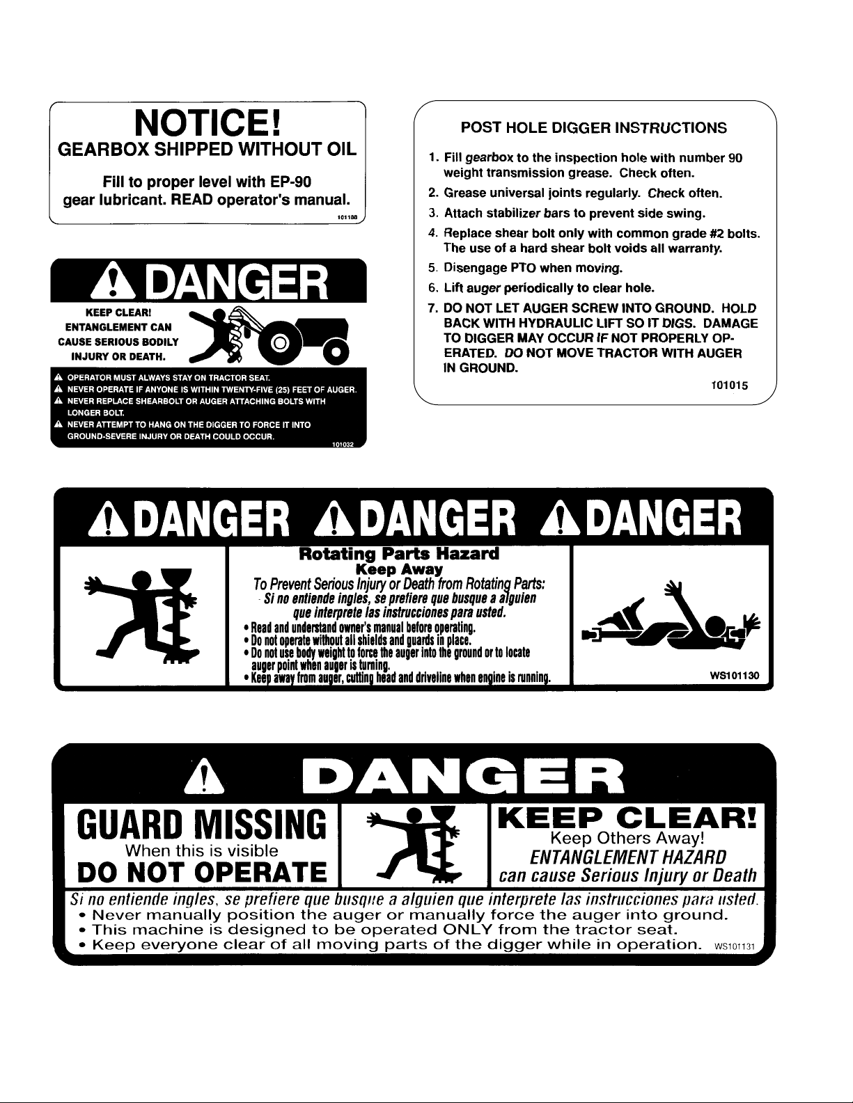
SAFETY SIGNS AND DECALS
LOCATED ON POST HOLE DIGGER BOOM
LOCA TED AT TOP OF AUGER CENTER TUBE
REMEMBER: If Safety Signs have been damaged, removed, become illegible or parts replaced without Signs, new
Safety Signs must be applied. New Safety Signs are available from your authorized distributor or factory.
9
Page 11

10
Be sure your tractor is in good condition. Read all
the safety precautions and make sure all tractor
operators are familiar with the safety rules of
operation.
CAUTION!
INSTRUCTIONS
TRACTOR REQUIREMENTS
AND PREPA R ATION
NOTE: If your tractor lift arm spacing is 32”, place the
pull pins on the outside of the yoke legs as shown in the
diagram. If your tractor lift arm spacing is 26” or less,
then place the pull pins on the inner side of the yoke legs.
The pins are Category I (
7
/8” dia.). If your tractor is
Category II, then lift arm bushings are required to
properly fit the 11/8” dia. Cat. II lift arm balls. (Bushings
not supplied.) Place the lift arms of your tractor over the
pull pins in the yoke and secure with linchpins (not
supplied).
Pin end of digger boom (Ref. #1) to tractor toplink
bracket. Raise boom by hand – check that it doesn’t hit
any part of toplink bracket (some tractors only). If
problem exists, change hole location and re-check.
Failure to check can result in boom damage. Cat. I
tractors need bushing. Connect yoke to boom with pin
(Ref. #12) and cotter pins.
NOTE: Always use adapter bushings when using
Category I pins on a Category II hitch. Trying to use Cat.
I pins in a Cat. II hitch without bushings will result in a
very sloppy fit and the post hole digger will be unstable.
NOTE: When attaching the yoke to the boom, use the
hole in the adjustment channel best suited for your
tractor. If you don’t know the best hole location, start with
the middle hole.
It is recommended that the gearbox output guard, the
gearbox input guard, and the PTO driveline be assembled on the gearbox before the gearbox is fastened to the
boom. Place the gearbox upside down on the floor.
Install the formed metal gearbox output shield (Ref. #9)
on the gearbox. A socket with a long extension makes
this an easy installation.
Clean and check the input shaft of the gearbox. If any
nicks or dents have occurred in shipping, lightly file to
remove and make the shaft smooth.
Slide the plastic cone-shaped input guard on to the
input shaft of the gearbox.
Grease the input shaft of the gearbox before installing
the PTO shaft. This reduces the chance of the PTO shaft
yoke from galling to the input shaft if the shear pin should
break.
Slip the two telescoping ends of the PTO shaft together .
Spray WD-40 into the yoke and wipe. This should
remove some of the paint and make it easier to slide the
yoke onto the input shaft of the gearbox. Install the
unsplined end on the gearbox input shaft and bolt it in
place with the
3
/8” shear bolt (Ref. #13) and secure with
the lock washer and nut.
Unpack all the bundles and lay out various parts. Start
with the yoke (Ref. #2). Place the pull pins (Ref. #10)
through the holes in the legs of the yoke and secure with
nuts and lock washers.
ASSEMBLY AND MOUNTING
The Model 720 3-pt. mounted post hole digger will fit
most Category I, Category II and some larger Category 0
tractors equipped with a standard 3-pt. hitch.
NOTE: Some Category 0 tractors have very short lift
arms or 5/8” diameter (Cat. 0) lift arm ball ends. These
tractors are not usually suitable for post hole digging
operation.
It is recommended that only tractors with wide front
axles be used with this implement. Tricycle front wheel
arrangements are inherently unstable and tractor rollover accidents are more likely to occur.
Check the tractor’s 3-pt. hydraulic lift system. It should
operate up and down smoothly and have enough power
to lift the dirt-loaded auger out of the hole. Refer to your
tractor operator’s manual or dealer for any adjustments
necessary to put the 3-pt. hydraulic lift system in good
working order. (I&Tshop manuals will list most specifications and adjustment instructions - available from most
farm equipment dealers.)
Check the shield over the PTO stub shaft. Make sure it
is in good condition and bolted securely to the tractor.
Purchase a new shield if old shield is damaged or missing.
Tractor must be equipped with stabilizer bars,
adjustable sway chains, or sway blocks to keep the post
hole digger from swinging side to side.
Smaller size tractors may need front counter weights to
counter-balance the weight of the post hole digger and
the weight of the dirt on the auger.
NOTE: Low profile tractors generally can only use 30”
long augers instead of standard 42” long augers. Some
low profile Category 0 tractors should use the Model 300
Post Hole Digger.
It is recommended that the tractor be equipped with a
Rollover Protection System (ROPS) and a seat belt that
is used.
Page 12
INSTRUCTIONS (continued)
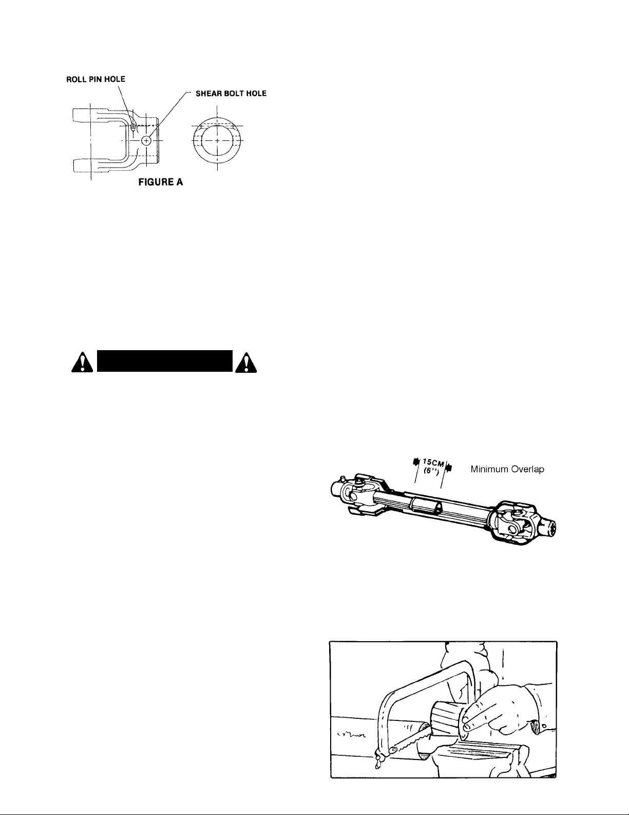
On the implement end of the PTO shaft there is a hole
in the yoke just forward of the 3/8” shear bolt (see Figure
A). This hole is for the 3/16” diameter x 11/4” long roll pin
(#2504011). When this roll pin is driven in this hole, the
center of the roll pin engages into the groove on the front
of the gearbox input shaft. This prevents the PTO
assembly from coming off if the 3/8” shear bolt should
shear. When replacing the shear bolt, use only a soft,
Grade 2 shear bolt. DO NOT use a hard bolt!
W ARNING!
Do not install a longer bolt or other longer fastener!
A protruding fastener is more likely to grab loose
clothing and can cause serious injury or death.
NOTE: If your tractor PTO shaft has a 11/8” spline, it will
be necessary to obtain a 11/8” to 13/8” sleeve spline
adapter. If tractor is equipped with a 11/8” to 13/8” spline
adapter extension, it may be necessary to cut the PTO
shaft off in length. Check this before putting the auger on
or digging a hole. To check, raise and lower the post hole
digger with the tractor BEFORE putting the auger on.
NOTE: The use of a PTO extension could require that
the PTO driveline be shortened a considerable amount.
If this is done, the driveline halves may separate when
the post hole digger is raised to transport position.
If the PTO driveline needs to be shorter, remove the
driveline from the tractor and digger gearbox. Lower the
digger (without the auger on) until the input shaft of the
gearbox is in line with the PTO stub shaft of the tractor.
(This should be the shortest distance required for the
driveline.)
Pull the two telescoping halves of the PTO driveline
apart. Connect the tractor end to the tractor and the gearbox end to the digger gearbox (but NOT with the two
halves together).
Hold the two driveline sections parallel to each other
and mark each end as to how much too long they are.
Then raise the digger to transport position and again
hold the two driveline halves parallel to each other and
check for a minimum of 6” (15 cm) overlap. If driveline
has less than 6” overlap, do not use. Contact your dealer.
If at least 6” of overlap is provided, then proceed in
cutting the driveline.
Attach the gearbox (Ref. #5) to the boom using the
gearbox hitch pin (Ref. #6) and secure it with the two
cotter pins (Ref. #7). The gearbox should be placed so
that the large shaft is pointing toward the ground and the
small shaft is pointing toward the tractor.
NOTE: The gearbox is shipped WITHOUT lubricant, so
it will be necessary to fill it before use. With the gearbox
in a level position, fill to the side inspection hole with a
good 90 wt. gear lubricant. Check often and add lubricant
if necessary.
Clean tractor PTO stub shaft and the inside of the
splined driveline yoke. Pull the spring loaded ring from
the end of the yoke and slip the splined driveline yoke on
the splined PTO shaft of your tractor. Release the spring
loaded ring and push the yoke on until it locks in place.
(The spring loaded ring holds locking balls that lock the
tractor end of the PTO driveline on the tractor PTO shaft.)
Make certain the tractor PTO shield is in good condition
and securely fastened onto the tractor.
Slowly raise and lower the digger without the auger on.
Watch to see that the PTO driveline and/or shields do not
separate or get into a bind. Check to see if gearbox end
will lower to the ground. If it will not go all the way down,
then either change the hole location between the yoke
and boom or check to see if the PTO shaft is bottoming.
Figure 1
1. If driveline must be cut to a shorter length, clamp
driveline in a well padded vise to prevent damage to
the shield. Cut off shield where marked. Using cut-off
section of shield as a guide, cut shaft the same
amount. (Figure 2)
Figure 2
11
Page 13
12
2. Repeat the procedure to the other driveline half.
Remove all burrs and cuttings.
3. Apply multi-purpose grease to inside of outer (female)
driveline section. Assemble driveline and install on
tractor and digger. Pull on each driveline section to be
sure yokes lock into place. Make certain driveline
shielding is in place and in good condition.
4. Carefully raise and lower the digger and check to be
sure the PTO assembly does not jam. If it does, cut
equal amounts from each half of the PTO assembly.
5. Check the swinging drawbar of the tractor and make
sure the PTO driveline assembly will not contact. The
swinging drawbar can be moved forward on some
tractors or it can be removed.
NOTICE!
PTO drivelines on model 720 post hole diggers
manufactured after October 1, 2000, do not have a
dimple protrusion on the square tube half of the
driveline or a groove in the 15/16” square shaft.
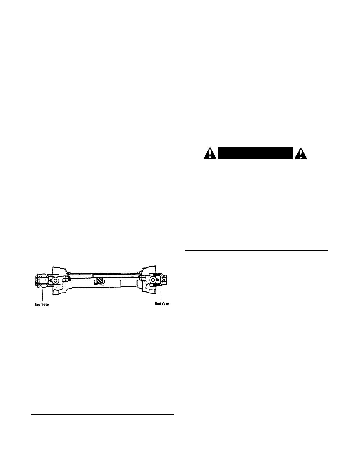
This means that it is possible to assemble the two
halves incorrectly.
Failure to properly align the end yokes may result
in excessive vibration.
Always make sure the end yokes are correctly
aligned when sliding the driveline halves back
together. See figure 3.
NOTE: Use stabilizer bars, adjustable sway chains,
or sway blocks on your tractor lift arms to keep the
post hole digger from swinging side to side. Adjust
as tightly as practical for best performance.
Slide the auger over the large shaft of the gearbox and
secure it with the two bolts, lockwashers and nuts. The
digger is ready to use.
INSTRUCTIONS (continued)
Operate the post hole digger only on a tractor with
540 RPM PTO shaft. The tractor’s engine speed
should not exceed 1200 RPM while digging.
CAUTION!
• Thoroughly read and understand your Operator’s
Manuals.
• Before beginning operation, clear area of objects that
wrap around the auger or might be thrown. Contact
local utility company to make certain there are no
buried gas lines, electrical cables, etc., in the work
area. Check for ditches, stumps, holes, or other
obstacles that could cause the tractor to roll.
• To dig properly, your digger must be able to raise or
lower through the highest and lowest points of your lift
arm travel without binding against the tractor frame.
Check carefully BEFORE attaching the auger. If it
does bind, adjust the tractor 3-pt. linkage so that all
movement is free.
If you have ANY questions, regarding the proper
operation of this digger, contact your dealer or the
manufacturer.
PREPARATION PROCEDURE
This Post Hole Digger was designed for one-man
operation from the tractor seat. It is the responsibility
of the operator to see that no one else is within
twenty-five feet (25’) of the digger when it is
operating.
• Set tractor brakes. Take tractor out of gear. Shift to
“Park” (if applicable).
• Do not allow anyone to stand behind, or to the side of
a rotating auger.
• Lower auger point slowly to the ground with the PTO
disengaged.
• With the auger point lowered to the ground, set the
engine speed to idle, then engage the PTO. Make
sure the auger point is on the ground before engaging the PTO.
• Increase the speed as required so dirt is conveyed
from the hole. Refer to Owner ’s Manual for suggestions on PTO speed.
• Under no circumstances should the PTO be run in
excess of 540 RPM.
O PE R ATION
Figure 3
Page 14

INSTRUCTIONS (continued)
• In some types of soil, it may be necessary to hold back
against the auger screw suction by moving the
hydraulic control lever to “HOLD” or “RAISE” position
to keep the auger from screwing into the ground.
• NEVER use body weight to help the auger
penetrate the ground. When the ground is too
tough to penetrate with your cutting edges and point,
sharpen or replace them and try again. These are
replaceable parts and must be in good condition to
penetrate. (Optional Hydraulic Downpressure Kit is
available – order #706080.)
• If you have difficulty penetrating hard ground, refer to
Owner’s Manual Troubleshooting section for
suggestions.
• When the auger has been lowered about a foot or so
into the ground, raise the auger almost out of the hole
to clear the dirt, then drill deeper and raise the auger
again. Repeat this procedure until the desired hole
depth is reached.
• Do not shovel dirt away from a rotating auger as the
shovel can be caught and thrown by the auger.
Engage the tractor PTO with the engine at idle (or below
1000 engine RPM). As the auger penetrates the ground,
lower the unit slowly with the 3-pt. hydraulic system. DO
NOT LET THE AUGER SCREW ITSELF INTO THE
GROUND! Auger must dig with the dirt breaking up and
being carried to the top by the auger flighting.
Once the hole is dug to the desired depth raise the
auger while rotating to bring the dirt out of the hole. To
get a clean hole, it is sometimes best to lower the auger
into the hole with the auger turning and then, when at the
bottom, stop the rotation and raise the auger while not
turning. This brings the dirt up with little left in the hole.
For best results, allow the digger to dig about half the
required depth, then lift it partially out of the hole to
remove dirt and then re-enter hole and finish to the
desired depth.
CAUTION!
• Disengage the power-take-off when traveling
between holes.
IT IS ESSENTIAL THAT EVERYONE INVOLVED IN
THE ASSEMBLY, OPERATION, TRANSPORT, MAINTENANCE, AND STORAGE OF THIS EQUIPMENT BE
AWARE, CONCERNED, PRUDENT, AND PROPERLY
TRAINED IN SAFETY.
The post hole digger auger is free-swinging, and care
should be taken while transporting the machine. DO
NOT transport the post hole digger while the PTO is
engaged as this could cause the universal joints of the
PTO driveline into a sharp operating angle and cause
failure of the driveline.
DIGGING A HOLE: Position the tractor so that the
auger point is placed where the hole is to be. Lower the
auger so that the point touches the ground. The point of
the auger should be approximately 3” back of center of
the gearbox. As the auger works into the ground, this
slight angle will straighten, due to the pivoting action of
the boom downward. If the auger has a side tilt, correct
with the lift arm adjustment on the tractor hitch.
If the auger tilts too far forward or to the rear, it may be
necessary to move the tractor slightly. Be careful not to
bend the auger.
Do not shovel dirt away from a turning auger, as the
shovel can be caught by the auger and thrown. Do
not allow anyone to stand behind or to the side of an
operating auger. ALL persons should be at least 25
feet away.
W ARNING!
Never locate auger by putting hands on auger,
gearbox, or boom when there is any sign of rotation
on the driveline or auger or if the tractor is running.
A Grade 2 (3/8” x 21/2”) shear bolt is included with your
post hole digger. If the shear bolt shears, replace only
with a soft, Grade 2 shear bolt. DO NOT USE A HARD
SHEAR BOLT! Use of a hard shear bolt could result in
damage to the gearbox or other post hole digger parts
and voids any warranty.
Do not run the digger while transporting, as damage to
the PTO shaft could occur.
DO NOT LET THE DIGGER DIG SO DEEP THAT THE
PTO SHAFT IS RUNNING IN THE DIRT.
13
Page 15
14
INSTRUCTIONS (continued)
Once the auger is digging a hole, the tractor cannot be
moved. Make sure brake is set securely. If the tractor
does move while the auger is in a hole, damage to the
gearbox or auger can result (not covered by
warranty).
Cutting edges and screw type center point are replaceable. They should be sharpened or replaced when worn.
In hard digging conditions, a fishtail type center point is
more aggressive and is recommended.
NOTE: Be sure auger is completely retracted from
the hole before attempting to move the tractor.
NOTE: If you have a rocky or large root soil condition, it
is recommended that a heavy duty auger by used.
If you encounter rocks or roots that catch the auger and
cause shear bolts to break, then remove the auger from
the hole and use a large, heavy pry bar to break up the
obstructing rock. Alarge root may have to be chopped to
remove.
NOTE: Please refer to the drawings (Figures B through
F) as to the proper mounting pattern for the cutting
edges. Correct mounting of the cutting edges will assure
a complete cut of earth by the auger.
If auger becomes lodged below ground, DO NOT
attempt to lift auger out of ground by hydraulic lift power
alone. Turn tractor of f and disconnect PTO driveline from
the tractor. Reverse the rotation of the auger by several
turns. This can be accomplished by using a large pipe
wrench and screwing the auger backwards until it clears.
Extreme rocking or lifting loads while trying to clear stuck
augers can cause auger, gearbox, or boom failure.
Remain on the tractor seat while operating the post
hole digger. Assisting the machine by hand can
result in possible injury or death.
W ARNING!
Do not attempt to free the auger while the PTO is
connected. Disconnect the PTO driveline from the
tractor before attempting to free the auger.
CAUTION!
Underground utilities – Contact appropriate
agencies to determine if hazardous items are buried
under the digging site BEFORE DIGGING! Be certain
underground utilities have been called to locate
underground electric, gas, telephone, and other
lines. Check your telephone book for calling instructions. Be sure post hole digger operator is properly
informed. WHEN IN DOUBT, DO NOT DIG!
CAUTION!
NOTE: Be careful when raising the auger as high
as your tractor’s 3-pt. hitch can go. This can put
the PTO shaft universal joints at an extreme
angle and cause damage to the PTO shaft! It is
best to raise the auger just enough to clear the
hole when the PTO is engaged.
It is recommended NOT to raise the auger while
it is running more than six (6) inches above the
ground.
Safety is a primary concern in the design and
manufacture of our products. Unfortunately, our
efforts to provide safe equipment can be wiped out
by a single careless act of an operator.
It has been said, “The best safety device is an
informed, careful operator.” We ask you to be that
kind of an operator.
NOTE: Never exceed the recommended auger
capacity of the post hole digger. The Model 720
heavy duty digger is designed for use with augers up
to 24-inch diameter. Use of an incorrect auger or
auger extension can cause equipment damage, loss
of operator control and personal injury.
Page 16

OWNER SERVICE
The information in this section is written for operators
who possess basic mechanical skills. Should you need
help, your dealer has trained service technicians
available. For your protection, read and follow all safety
information in this manual.
W ARNING!
▲ Lower post hole digger to ground or block
securely, turn tractor engine off, remove key and
disconnect PTO driveline from tractor PTO before
performing any service or maintenance.
▲ Before working underneath, raise 3-pt. hitch to
desired position and block securely. Hydraulic
system leakdown and failure of mechanical or
hydraulic system can cause equipment to drop.
▲ Keep all persons away from operator control area
while performing adjustments, service or maintenance.
ROUTINE MAINTENANCE
DAILY CHECKS:
1. Check that all bolts, nuts, and screws are tight.
Checking the bolts and nuts on the cutting blades is
particularly important in rocky soil.
2. Check daily the level of the gearbox oil and top up to
the correct level. Check for gearbox oil leaks. It should
be noted that no warranty claim can be submitted on
a gearbox that has run dry. It is essential that the
gearbox is kept correctly filled with gearbox oil.
3. Grease the PTO shaft daily.
4. Check the wear on the cutting blades. Sharpen them
routinely with an angle grinder or replace when worn
down too far. Keep at least two sets of cutting blades,
bolts, and nuts as spares.
Daily lubrication of the PTO slip joint is necessary.
Failure to maintain proper lubrication can result in damage
to U-joints, gearbox, tractor PTO and/or driveline.
AT THE END OF THE SEASON:
1. Drain and change the oil in your gearbox.
2. Check and replace, where necessary, blades, bolts,
nuts on the machine.
3. Clean machine and touch up any rust spots that may
have appeared.
4. Replace any safety signs if damaged or painted over.
5. Make sure PTO driveline yoke and gearbox input
shaft are clean and free of burrs. Keep well lubricated
to prevent galling of yoke and input shaft when shear
bolt becomes sheared.
6. Keep all shields in place. Order new shields if dam-
aged or missing.
7. Keep cutting edges sharp. Sharp cutting edges dig
easier and better. Outer cutting edges on larger
augers wear faster than inner cutting edges; switching
teeth will even wear.
8. Store implement in clean, dry location.
TRANSPORTING
Pay particular close attention to the Safety Messages
regarding transport. Avoid unnecessary injuries and
equipment damage by exercising cautious, conscientious travel procedures.
Attaching the implement to the tractor increases the
overall length of the working unit. Allow additional
clearance for the implement to swing when turning.
Raise the implement as high as possible for transporting.
DO NOT OPERATE PTO DURING TRANSPORT.
LUBRICATION INFORMATION
The accompanying chart gives the frequency of lubrication in operating hours, based on normal conditions.
Severe or unusual conditions may require more frequent
lubrication.
Do not let excess grease collect on or around parts,
particularly when operating in sandy areas.
Use an SAE 90W gear lube in gearbox.
Use a lithium grease of NO. 2 consistency with a MOLY
(molybdenum disulfide) additive for all locations. Be sure
to clean fittings thoroughly before attaching grease gun.
When applied according to the lubrication chart, one good
pump of most guns is sufficient. Do not over grease.
LUBRICATION CHART
REF NO. DESCRIPTION FREQUENCY
1 Front U-Joint 8 Hrs.
2 Rear U-Joint 8 Hrs.
3
Gearbox – Fill to proper level
Check Daily
REMOVING DIGGER FROM TRACTOR
Post hole diggers when off the tractor, can be an
awkward piece of equipment to handle. Be careful not to
pinch hands and fingers in the various hinge points of the
digger.
If possible, it is suggested to hang the digger from an
overhead rafter or beam. Attach the chain or rope around
the boom just ahead of the gearbox. This allows one man
to easily reconnect the digger to the tractor when next
use is required.
If storing outside, hanging from a good solid tree limb
has worked for some owners. If storing outside, another
idea is to dig a hole about 12-18 inches deep. Then shut
the PTO off while the auger is in the hole and disconnect
the digger from the tractor. The auger in the hole will
keep the unit upright and make it possible for one man to
disconnect or reconnect to the tractor. Doing this, will
cause rusting of the auger, but it is easy for one man to
handle the unit.
15
Page 17

16
TROUBLESHOOTING GUIDE
PROBLEM: AUGER WILL NOT DIG
Possible Solutions:
• Shear bolt sheared – install new shearbolt.
• Teeth dull – sharpen or replace.
• Ground too dry and hard – order optional fishtail point
(#170802) or optional down force kit, or wait until it
rains.
• Auger turning too fast and bouncing – reduce speed.
• Tall grass has wrapped around auger teeth – remove.
• Auger encountering rocks, roots, or other obstruction –
lift auger from hole and inspect.
• Auger teeth improperly positioned – see operator’s
manual for proper tooth pattern.
PROBLEM: AUGER DIGS SO FAR, BUT WILL NOT
DIG DEEPER
Possible Solutions:
• See solutions for above.
• PTO assembly “bottoms out,” not allowing digger to
lower – remove auger from digger and lower digger.
Gearbox should lower to the ground; if not, PTO
driveline assembly may need to be shortened.
• PTO driveline interferes with swinging drawbar – swing
drawbar out of the way or remove.
• Tractor hydraulic system may be faulty – consult tractor dealer.
• Soil could have hardpan layer 6”-10” below surface –
use optional fishtail point (#170802) or optional down
force kit (see list of optional equipment).
PROBLEM: POST HOLE DIGGER SWAYS SIDE TO
SIDE
Possible Solutions:
• No sway bars or sway blocks on tractor – add same.
• Lift arms not adjusted evenly – adjust lift arms.
• Post hole digger is mounted with excessive looseness
in the hitch connecting points – use proper size pins or
bushings.
PROBLEM: BENT AUGER FLIGHTING OR BENT
AUGER
Possible Solutions:
• Tractor moved while auger was turning in hole –
always set brakes on tractor and make sure it is out
of gear.
• Operator moved tractor with auger in hole to try and
straighten a hole being dug at an angle.
• Auger is encountering rocks or roots or other foreign
objects – remove object from hole or change location.
• Outer edge of auger flighting is bending due to contact
with rocks or roots – use heavy duty auger with thicker
flighting.
• Shear bolt has been replaced with harder bolt –
replace with Grade 2 bolt per instructions.
THIS IS A DANGEROUS SAFETY HAZARD,
CORRECT IMMEDIATELY!
PROBLEM: AUGER SCREWS ITSELF INTO THE
GROUND
Possible Solutions:
• Operator did NOT ease 3-pt. hitch to ground slowly.
• Faulty 3-pt. hitch hydraulic system on tractor.
• Draft control is not in OFF position.
• Tractor is too small to handle digger.
PROBLEM: EXCESSIVE VIBRATION
Possible Solutions:
• PTO driveline halves are mis-aligned. Pull PTO driveline halves apart and reassemble. Make sure end
yokes are aligned correctly.
• PTO driveline bearing cross is worn – replace.
PROBLEM: PTO DRIVELINE ASSEMBLY COMES
OFF INPUT SHAFT OF GEARBOX
WHEN SHEAR BOLT IS SHEARED.
Possible Solution:
• Roll pin missing in yoke at gearbox input shaft. Install
roll pin as per instructions.
W ARNING!
Page 18

TROUBLESHOOTING (continued)
PROBLEM: PTO DRIVELINE FAILURE
Possible Solutions:
• Operator raising post hole digger too high above
ground when PTO is engaged – causes excessive
PTO joint operating angle.
• PTO is engaged while moving between holes. (Auger
swings, which causes excessive PTO joint operating
angle.)
• Improper use of a hard shearbolt – use Grade 2 bolt
per instructions.
• Driveline has not been properly lubricated.
• Engaging tractor PTO with engine at high rpm.
• Digging holes too deep so that PTO driveline contacts
ground.
• Operating at high rpm.
• Use of auger extension can require post hole digger to
be lifted high, which can cause excessive PTO joint
operating angle.
• Tractor is a “low profile model” (one that is low to the
ground). Due to the low height of the tractor, the digger
must be raised higher to have the bottom of the auger
clear the ground. Generally, low profile model tractors
can only use 30 inch long augers (standard auger
length is 42”). Use a different tractor or purchase 30”
long augers.
PROBLEM: PTO DRIVELINE “GALLS” OR “FRIC-
TION WELDS” TO INPUT SHAFT OF
GEARBOX
Possible Solution:
• No lubrication on input shaft of gearbox to allow yoke
of PTO driveline to turn freely on input shaft when
shear bolt is sheared. Always keep input shaft
greased.
PROBLEM: GEARBOX FAILURE
Possible Solutions:
• No oil in gearbox.
PROBLEM: GEARBOX OVERHEATING
Possible Solutions:
• Low on lubricant – fill to proper level.
• Improper type lubricant – replace with proper lubricant.
PROBLEM: AUGER BOLTS SHEAR ON GEARBOX
OUTPUT SHAFT
Possible Solutions:
• Shearbolt on input shaft has been replaced with a
harder bolt – replace with Grade 2 bolt as per instructions.
PROBLEM: TRACTOR STALLS
Possible Solutions:
• Auger is encountering rocks or roots or other foreign
object – remove object or change hole location.
• Tractor idle is not set correctly – tune tractor engine.
POST HOLE DIGGER OPTIONS
1. Heavy Duty Augers: Augers with heavier flighting
and a reinforced drive tube are available for rocky or
tough soil conditions. Check with dealer for
availability.
2. Heavy Duty Fishtail Center Point: Recommended
for tough or rocky soil conditions. The fishtail point will
work around smaller rocks. Order part #170802.
3. 12” Auger Extension: Available for situations where
deeper holes are required. NOTE: Smaller tractors
may not raise auger high enough to clear hole when
12” auger extension is used. Order part #170705.
4. Hydraulic Down Force Kit: For tough, hard soil
conditions. This will allow operator to put 300-400 lbs.
of down force on the auger to force cutting edges into
tough or hard ground. Tractor must have auxiliary
hydraulic outlet. Order part #706080 for Model 720
Post Hole Diggers.
• Oil not changed per instructions.
• Shear bolt has been replaced with a harder bolt –
replace with Grade 2 per instructions.
• Bent output shaft is due to operator moving tractor
when auger is in hole.
ALWAYS OBEY ALL
SAFETY WARNINGS!!
17
Page 19
18
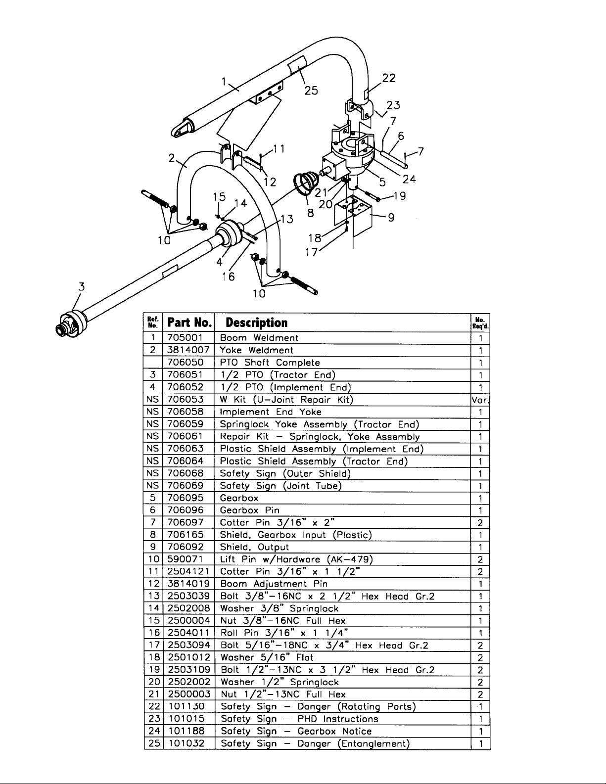
MODEL 720
POST HOLE
DIGGER
PA RTS LIST
Page 20
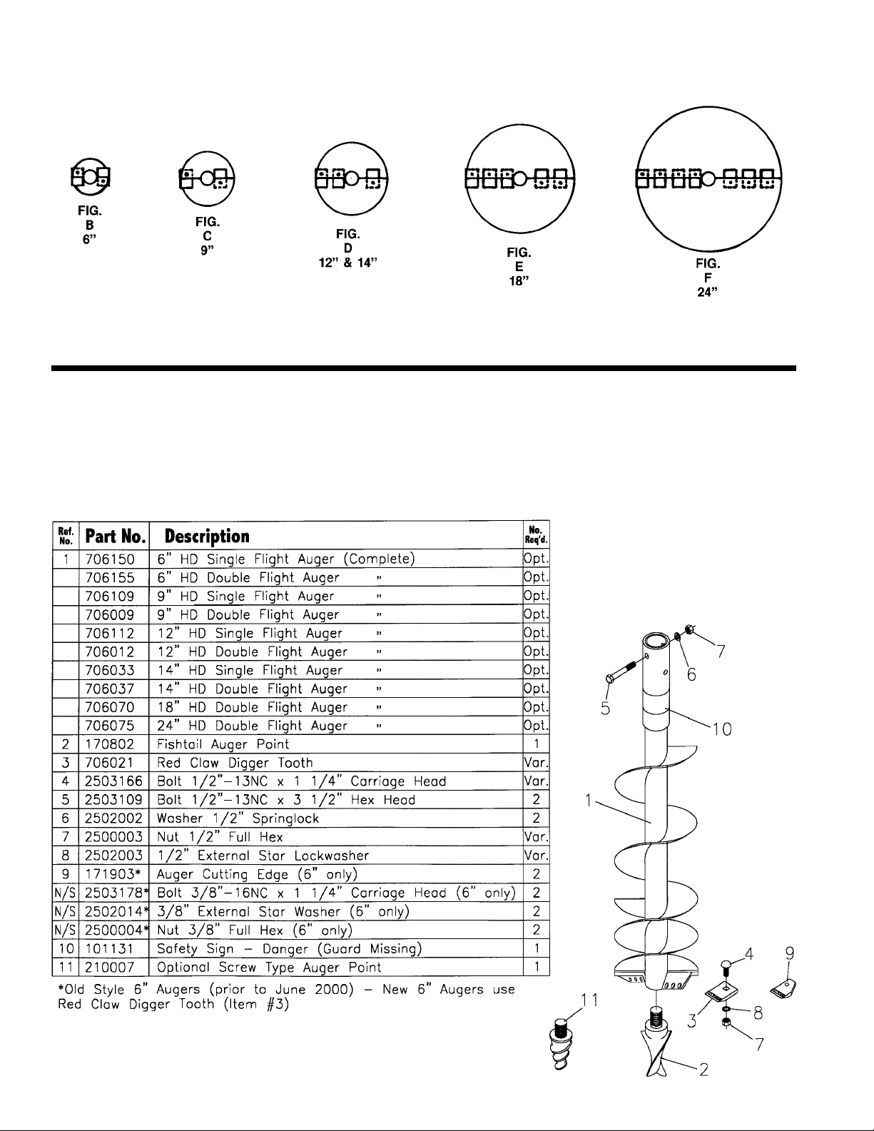
AUGER TEETH MOUNTING PATTERNS
HE AVY DUTY AUGER PA RTS LIST
19
Page 21
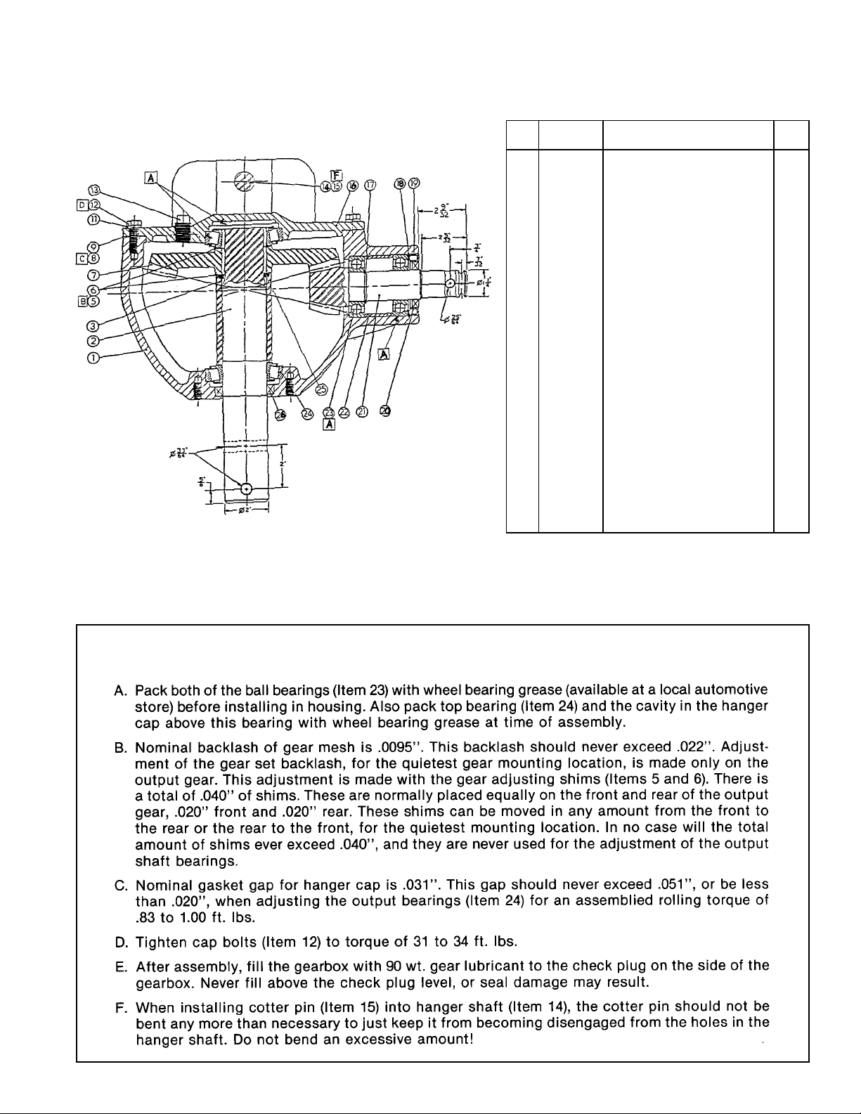
GEARBOX REPAIR PROCEDURE
20
1 706120 Housing 1
2 706121 Output Shaft 1
3 706122 Output Bearing Spacer 1
5 706123 Gear Adjusting Shim 0.30 Var.
6 706124 Gear Adjusting Shim 0.50 Var.
7 706125 Output Gear, 38 Tooth 1
8 706126 Output Cap Gasket 0.10 Var.
9 706127 Output Cap Gasket 0.25 Var.
11 706128 #10 Lockwasher 8
12 706129 M10 x 1.5 x 30 Cap Screw 8
13 706130
1
/2” Pipe Plug 2
14 706096 Hanger Shaft 1
15 706097 Cotter Pin 2
16 706131 Hanger Cap 1
17 706132 Retaining Ring 1
18 706133 Retaining Ring 1
19 706134 Seal Adapter 1
20 706135 Input Seal 1
21 706136 11 Tooth Pinion & Shaft 1
22 706137 Bearing Spacer 1
23 706138 207K Ball Bearing 2
24 706139 Bearing Assembly 7210 2
25 706140 Retaining Ring 1
26 706141 Output Seal 70 x 50 x 12 1
PART
NO.
DESCRIPTION
NO.
REQ.
REF.
NO.
GEARBOX REPAIR PA RT S
Page 22
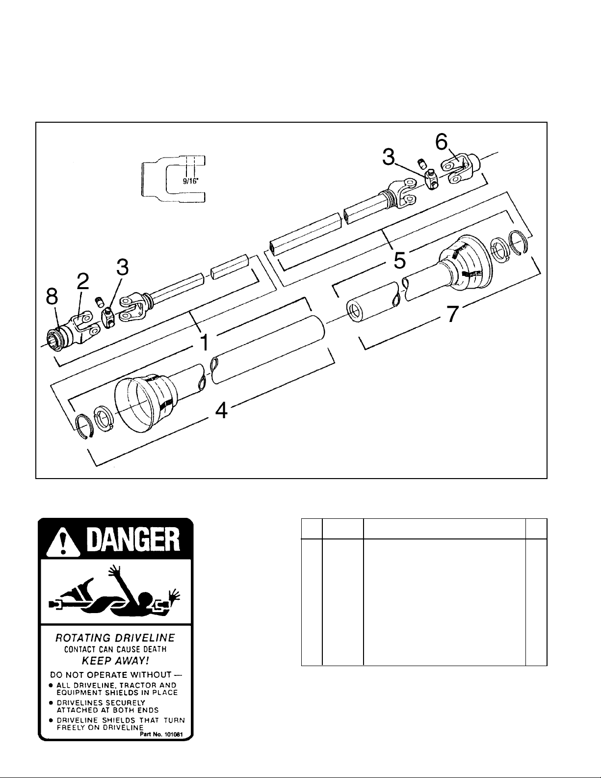
MODEL 720 POST HOLE DIGGER
PTO SHAFT (Shear Bolt Protected)
R E PAIR PA RT S
REF.
PART
NO.
NO.
706050 PTO Shaft, Complete 1
1 706051
2 706059 Spring-Lock Yoke Assembly (Tractor End) 1
3 706053 W Cross & Bearing Kit 2
4 706064 Outer Guard (Tractor End) 1
5 706052
6 706058 Shear Bolt Yoke Assembly (Imp. End) 1
7 706063 Inner Guard (Implement End) 1
8 706061 Spring-Lock Repair Kit 1
1
/2PTO (Tractor End) 1
1
/2PTO (Implement End) 1
DESCRIPTION
21
NO.
REQ.
Page 23
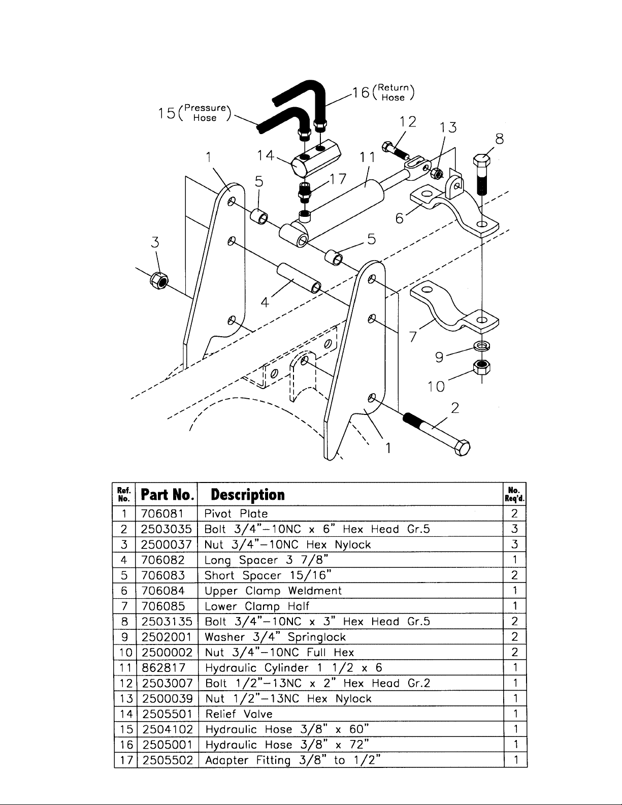
221
DFK-70 DOWN FORCE KIT PA RTS LIST
Page 24

SAFETY PRECAUTIONS
MOST ACCIDENTS OCCUR BECAUSE OF NEGLECT OR CARELESSNESS.
AVOID NEEDLESS ACCIDENTS BY FOLLOWING ALL OF THE SAFETY PRECAUTIONS LISTED BELOW.
• Machinery should be operated only by those who are
responsible and are authorized to do so.
• Stop the engine, lower all equipment, lock the brakes,
and remove the ignition key before dismounting from the
tractor.
• Never stand between tractor and implement while tractor
is being backed to hitch.
• Loose fitting clothing should not be worn, to avoid catch-
ing on various parts.
• Detach implement in area where children normally do not
play.
• When performing adjustments or maintenance on an
implement, first lower it to the ground or block it securely
at a workable height.
• Only a qualified operator should be permitted on tractor
when in operation; no riders allowed.
• Make certain everyone is in the clear before starting
tractor or raising or lowering equipment.
• Operate the tractor and implement only while seated in
the driver’s seat.
• Reduce speed when transporting mounted implements to
avoid bouncing and momentary loss of steering control.
• A heavy load can cause instability of the tractor. Use
extreme care during road travel. Slow down on turns and
watch out for bumps. Tractor may need front counterweights to counter-balance the weight of the implement.
• Reduce speed on hillsides or curves so there is no
danger of tipping.
• Avoid driving too close to the edge of ditches or creeks.
• Do not transport implement on public roads without
reflectors and slow moving vehicle emblem in daylight
and with approved warning lights at night and other
periods of poor visibility.
• Due to the width of some implements, use extra caution
on highways, farm roads, and when approaching gates.
• Always be sure the implement is in the proper position for
transport.
• Keep alert and watch the front as well as the rear when
working with the implement.
OWNER’S/
OPERATOR’S
MANUAL
MODEL NO.
720
WHEN ORDERING
REPAIR PARTS,
ALWAYS GIVE
THE FOLLOWING
INFORMATION:
1. PART NUMBER
2. PART DESCRIPTION
3. MODEL NUMBER
4. NAME OF ITEM
LIMITED WARRANTY
Farm Star warrants its implements, parts and accessories to be free from
defects in materials and workmanship for a period of six (6) months from date
of purchase. Upon written approval Farm Star will repair or exchange
without charge any part, which upon examination by Farm Star or its
authorized agent, shall disclose to be defective.
This does not apply to (1) parts that have worn out in normal use, (2) parts
broken because of improper assembly or operation by the customer, (3) parts
accidentally damaged, (4) failure of parts traceable to improper care, (5) parts
failing through use of implement for purposes other than those for which it
was designed.
Additions to Limited Warranty
In addition to the Standard Limited Warranty printed above,
Farm Star provides:
1. Five years’ (60 months) warranty on the gearbox and,
2. One year (12 months) on the driveline if:
all of these components have been properly maintained and lubricated and
that they have not been subjected to abuse or misuse.
The obligations assumed by Farm Star and the limitations expressed
herein are in lieu of all other warranties expressed or implied.
Commercial use warranty, 90 days on unit and driveline, one year on gearbox
from date of sale.
NOTICE: Farm Star is NOT responsible for damage to augers caused
by hitting underground objects (rocks, roots, etc.) or for bent augers
caused by moving the tractor with the auger in the ground.
JANUARY 2001
FS-PH003-OG
FARM STAR
P.O. BOX 100 LITCHFIELD, IL 62056-0100 (217) 324-5973
WEB: http:// www.farmstar.com E-MAIL: [email protected]
 Loading...