

Page 1
Uncasville, CT
INSTRUMENTS
10
M
A
D
T
E
C
,
40
Km/h
50
I
80
N
U
.
30
60
70
E
L
L
I
V
S
A
C
N
U
.
P
R
O
C
®
A
I
R
A
F
20
30
20
10
0
0 50
MP H
S
.
A
.
1
6
6
8
-
5
0
-
3
7
A
40
Electronic
Programmable
Speedometer
(Basic)
IS0218
ISO218A ECR#5294 03/05
Page 2

Index
Description
Odometer Page 1
Trip Odometer Page 1
Hour-meter Page 1
Maximum Saved Speed Page 1
Setting the Speedometer Page 2
Boot menu Page 2
Service Hours Page 2
Service Distance Page 3
Clear Hours Page 3
Clear Distance Page 4
Program High Axle Page 4
Program Low Axle Page 4
Input Level control for the speed pulse input Page 4
Run Menu
Clear Odometer Page 5
Set Speed (Over Speed indicator) Page 5
Calibrate Hi Axle Page 5
Calibrate Low Axle Page 6
Harness P1 6 pin connector Page 8
Harness P2 4 pin connector Page 9
Page 3
COMMERCIAL SPEEDOMETER
Functions available:
1. Odometer display
2. Trip odometer display (resetable)
3. Change the pulses per mile or the
pulses per kilometer input.
A. PPM adjustment can be done
automatically by the microprocessor.
B. PPM numbers can be entered using
the push-button.
C. All features available for both high
and low speed axles.
Detail description
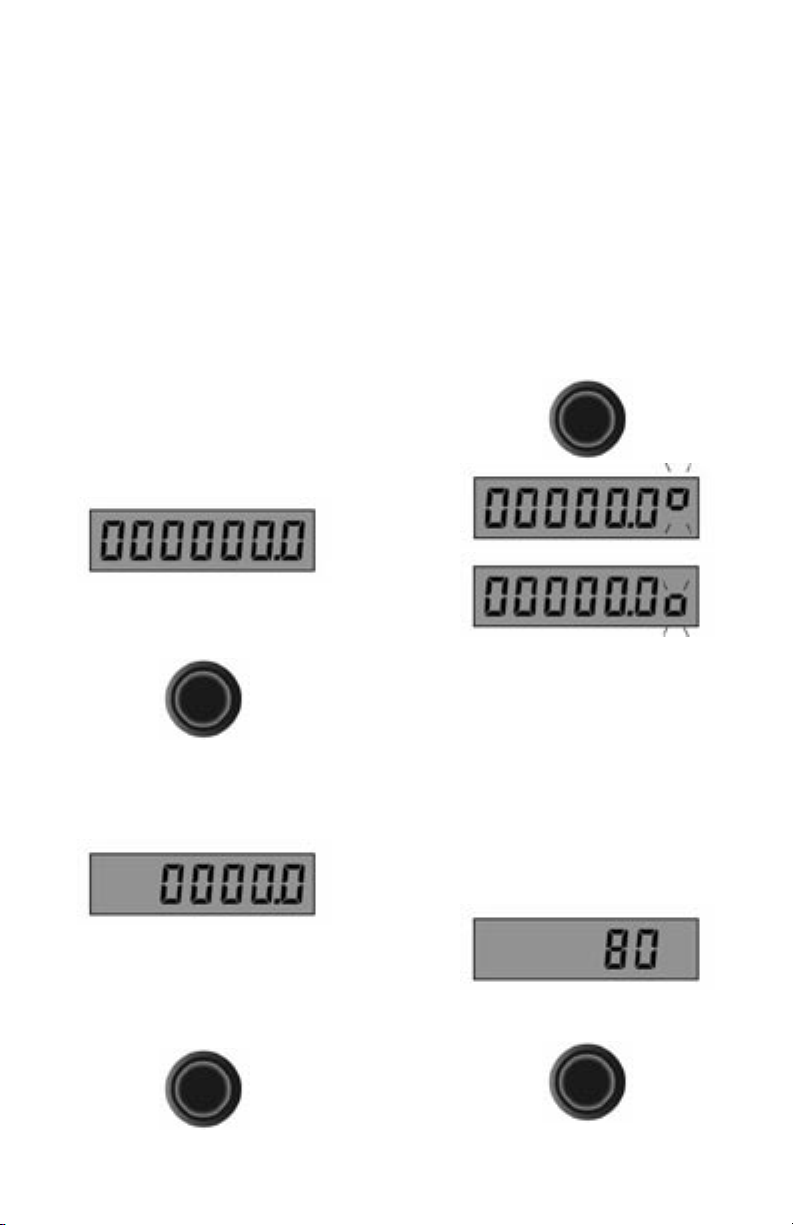
Odometer
The commercial speedometer contains an
odometer to maintain a record of the total
mileage and trip mileage. During normal
operations and after a power on the odometer
display shows;
This display cannot be reset. A quick press
of the push-button changes the display to the
Trip odometer.
Trip Odometer
The Trip odometer allows you to keep
a record of the trip miles or kilometers
independent of the Odometer.
to indicate mph (or kph) indicates the speed.
The kph is handled the same as a mph in the
microprocessor. The pulses per mile will be
pulses per kilometer and the self-cal will
be for 1 kilometer instead of 1 mile. There
is no provision to change from miles to
kilometers.
Hour-meter
The speedometer also contains an hourmeter that is always activated by an external
input so that actual engine hours can be
recorded. Quick press the push-button while
in the Trip Odometer function displays the
Hour-meter.
The last digit on the right blinks up and
down indicating the hour-meter function.
The hour-meter cannot be reset.
Maximum Saved Speed
This speedometer will also record the
maximum speed under normal conditions.
The maximum speed is displayed and
changes as the speed is increased over the
current maximum.
The Trip Odometer is fully user resetable.
While in the Trip Odometer display press
the push-button for 4 seconds and the Trip
odometer is reset to zero.
The pointer travels over a 270-degree dial
The maximum speed can be reset by pressing
the push-button for 4 seconds.
Another feature of the speedometer is to keep
track of and indicate when a service interval
Page 1
Page 4
has passed. The interval can be either or both
mileage and hours.
A seven digit display readout displays
the total mileage, the trip mileage, hourmeter or maximum saved speed (cleared
by pressing and holding the push-button
for 4 seconds while in the maximum speed
display), the menu items are scrolled by
pressing and releasing the push-button on
the speedometer.
If a service interval has been passed the
display will show a service message (one
time only).
Service Hours
Service Distance
push-button is pressed and held on when
power is first turned on the “boot menu” will
be activated.
The second menu, the “run menu”, can be
activated during normal running time by
pressing and holding the push-button for two
seconds.
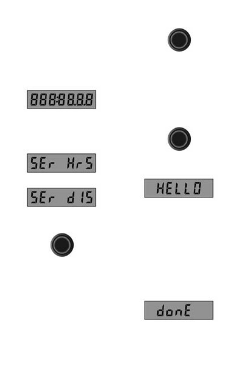
Boot menu
Pressing and holding the push-button while
power is turned on will activate the “boot
menu”.
The display will show “HELLO” and wait
for you to release the push-button.
Pressing the push-button will return the
display to the primary mileage and hour
displays.
The service interval message will also
show once every time the speedometer is
powered up. The display can be cleared by
the push-button. The pulses per mile output
from the sensor to the speedometer can be
programmed by hand or done automatically,
for both of the high and low range axles.
Setting the speedometer
There are two major speedometer setting
routines.
The first is activated during boot-up. If the
Page 2
When the push-button is released the first
item on the menu will be shown. In four
seconds the microprocessor will activate that
menu feature.
If you want a different item from the menu,
you must press and release the push-button
before four seconds have elapsed. The menu
items will scroll continuously. If you want
to get out at this point with no changes, stop
at the last menu item “donE”, and in four
seconds the microprocessor will return to
normal with nothing being changed.
If you are in a menu, just do nothing for 32
seconds and the microprocessor will restart
and change nothing.
1. The first menu item “SEr HrS” (Service
Page 5

Hours) is used to set the next service interval
in hours.
When this menu feature is started, the display
will show the actual hours when the present
hour service interval will occur.
The main purpose of this menu feature is
to set the next hour service interval time,
however it can also be used to check when the
present service interval will occur. Starting
at the left most digit, the digits will flash on
and off for four seconds.
During this time you may change the digit by
pressing and releasing the push-button.
Once you have changed the digit once you
may push and hold the push-button to have
that digit count continuously from 0 to 9.
When you have made your digit choice, don’t
touch the push-button for four seconds and
the next digit to the right will now flash and
be accessible for change.
this point and nothing will change in the
microprocessor controller.
To save the changes you have made in the
display, you must press and hold the pushbutton while any digit is flashing.
The digit will stop flashing and four seconds
later the microprocessor will reset any
previous events pertaining to the hour service
interval, and install the new numbers. When
the microprocessor is finished the display
will change to “donE”.
The trip switch must now be released to
return to normal operation. If the present
hour-meter is close to 999,999, your new
number may be past the overflow so when
you examine when the hour service event
will occur, the number shown will be less
then the current hour-meter. This is because
the current hour-meter must overflow and
start at zero before the service event can
occur.
2. The second menu item “Ser diS”(Service
distance) will allow you to program the
mileage service interval.
This will continue for all the digits and will
go back to the first digit and repeat. If the
push-button is not pressed for 32 seconds the
microprocessor will return to normal and
will change nothing.
This is useful if you’re only here to check
when the present service interval will occur.
The operator may also turn power off at
The description and operation are the same
as number 1 above except the mileage service
interval is changed or observed.
3. The third menu item “Clr HrS” (Clear
Hour Service) allows you to clear the hour
Page 3
Page 6

service flag and automatically reset the next
hour service.
for 32 seconds and the microprocessor will
reset itself and will change nothing.
The calculation will use the previous interval
value. When the operator stops at the “Clr
HrS” display and waits four seconds the
service interval will be changed.
4. The fourth menu item “Clr diS” (Clear
distance) allows you to reset the mileage
service interval.
The implementation is the same as number
3 above.
5. The fifth menu item “PPgn Hi” (Program
High axle) will allow the operator to enter
the pulses per mile or kilometer for the high
axle.
This number will depend on how your
particular sender is arranged. The maximum
pulses per mile or kilometer are limited
to 150,000. When you stop at the “PPn
HI” display and wait four seconds the
microprocessor will display six digits with
the left most digit flashing.
Holding the push-button on for four seconds
while a digit is flashing will make the
microprocessor compute the observation
window and will store this window and the
pulses per mile or kilometer rounded off
to the nearest 100 pulses in the EEPROM.
The display will now show “donE” and the
operator should release the push-button to
resume normal operations.
6. The sixth menu feature “PPgn LO”
(Program Low axle) is used to program the
low speed axle pulses per mile or kilometer.
This function is not operative.
7. The next item in the menu is the input level
control for the speed pulse input. The display
will show “ InPuT “.
If nothing is done for 4 seconds then the
display will change to “L n H” and the L
will be flashing and every 4 seconds the next
letter will flash.
The number displayed will be the present
pulses per mile or kilometer rounded off to
the nearest 100 th. The right most digit will
be a “P” to remind the operator that they
are in the “Programming” mode. The digit
changes and inputs are the same as number 1
(Service Hours) above.
Also present is the same option to do nothing
Page 4
If the button is pressed when any selection
is flashing, that input signal level will be set
to that level.
The choices are low, normal and High. Low
Page 7

is normally used for magnetic pickups and
normal and high for other types.
8. The last menu item “donE” is used to exit
from this menu.
Leaving the display in “donE” for four
seconds will cause the microprocessor to
go back to normal operations and change
nothing.
Run menu
Pressing and holding the push-button for
two seconds during normal operation will
activate the “run menu”.
The display will show “HELLO” and wait
for you to release the push-button.
and change nothing.
1. The first item in the run menu is “Clr
OdO” (Clear trip odometer).
If the operator stops at this display, the
microprocessor will reset the trip odometer
to zero and will return the microprocessor to
its normal operation.
2. The second menu item “SET SPd” (Set
Speed) is used to set the speed at which the
over-speed indicator will activate.
Not installed.
Stopping at this display and waiting four
seconds will set the display to three digits
corresponding to the last speed that the overspeed was set to.
When the push-button is released the first
item on the menu will be shown. In four
seconds the microprocessor will go to the
first menu feature.
If you want a different item from the menu,
you must press and release the push-button
before four seconds have passed.
The menu items will loop continuously.
If you want to get out at this point with no
changes, stop at the last menu item “donE”,
and in four seconds the microprocessor will
return to normal with nothing being changed
or if you are in a menu, just do nothing for 32
seconds and the microprocessor will restart
The left most digit will be flashing and the
change and implementation of the input
numbers are the same as above. When the
push-button is held for four seconds the
microprocessor will set the number in the
display to be the new over-speed trip point.
The option to get out with no changes is
available by not making any changes for 32
seconds.
3. The third menu feature “SELF HI” (Self
calibrate high axle) can be activated by
waiting at this display for four seconds.
This is a feature to allow automatic setting
Page 5
Page 8

of the high axle pulses per mile or kilometer
that the speedometer will use to position the
pointer and record the correct mileage.
This is accomplished by indicating to the
speedometer microprocessor, the beginning
and end of a measured mile or kilometer. The
microprocessor will actually count the pulses
that occurred during that mile or kilometer
and compute the required parameters. When
this mode is activated the speedometer will
display “PEndInG “.
This means that the microprocessor is
waiting for the push-button to be pressed
indicating the beginning of the measured
mile or kilometer.
When the push-button is pressed and
released the display will change to “SELF
HI” indicating that the microprocessor is
now counting pulses.
the display will show “CALCInG”
(Calculating)
while the microprocessor calculates the
numbers it needs and will restart. The new
pulses per mile or kilometer will now be in
effect. This feature may be abandoned at
anytime by pressing and holding the pushbutton for two seconds. The microprocessor
will reset itself and continue normal
operations. This menu item may also
be stopped by turning off power to the
speedometer.
4. The forth menu item “SELF L ” (Self
calibrate low axle) is used to automatically
calculate the pulses per mile or kilometer for
the low ratio axle.
Not installed in this application.
The speed at this point is not important. The
operator may even stop and wait, as long as
power is not turned off and the measured
mile or kilometer is followed as straight as
possible, the operator may not turn around
and go in the opposite direction.
Also for the maximum accuracy, the operator
should not enter any off road parking as
this would deviate from a straight mile or
kilometer measurement.
At the end of the measured mile or kilometer
the operator must press and release the pushbutton one more time,
Page 6
The implementation and setting are the same
as number 3 “SELF HI” above.
5. The last feature “donE” is used to exit
from this menu. If this display is left on for
four (4) seconds and the push-button is not
pressed, the microprocessor will return to
normal operation with nothing changed.
Page 9

Shrink Tubing
or Wrap
Harness P1
6 - pin connector
Pin A Battery Input
Pin B Ground
Pin C N/A
Pin D External Push-Button grnd
Pin E N/A
Pin F N/A
Page 8
N/A
N/A
External push button (ground active)
N/A
Ground
Battery input
P1
P2
Page 10

P1
P2
Harness P2
4 - pin connector
Shrink Tubing
or Wrap
Pin A Sensor Power
Pin B Speed Signal
Pin C Ground
Pin D N/A
Power for external sensor
Speed pulses in from sensor
Ground
N/A
Page 9
Page 11

Notes:
Page 10
Page 12

Copyright 2005 by the Thomas G. Faria Corporation, Uncasville CT, all rights reserved.
No part of this publication may be reproduced in any form, in an electronic retrieval system or
otherwise, without the prior written permission of the company.
 Loading...