

Page 1
ACI s.r.l. FARFISA INTERCOMS
Via E. Vanoni, 3
62029 OSIMO (AN) - ITALY
Tel. (+39)071.720.20.38
Fax (+39)071.720.20.37
e-mail: [email protected]
www.acifarfisa.it
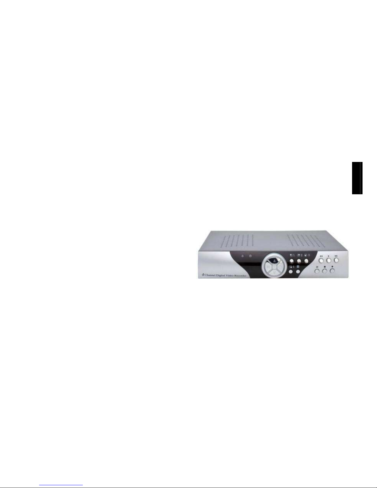
DVR42E
4CH Digital Video Recorder
User’s Manual
(Rif Mi3159)
Before operating the unit, please read carefully this manual and keep for future
reference
ENGLISH
Page 2
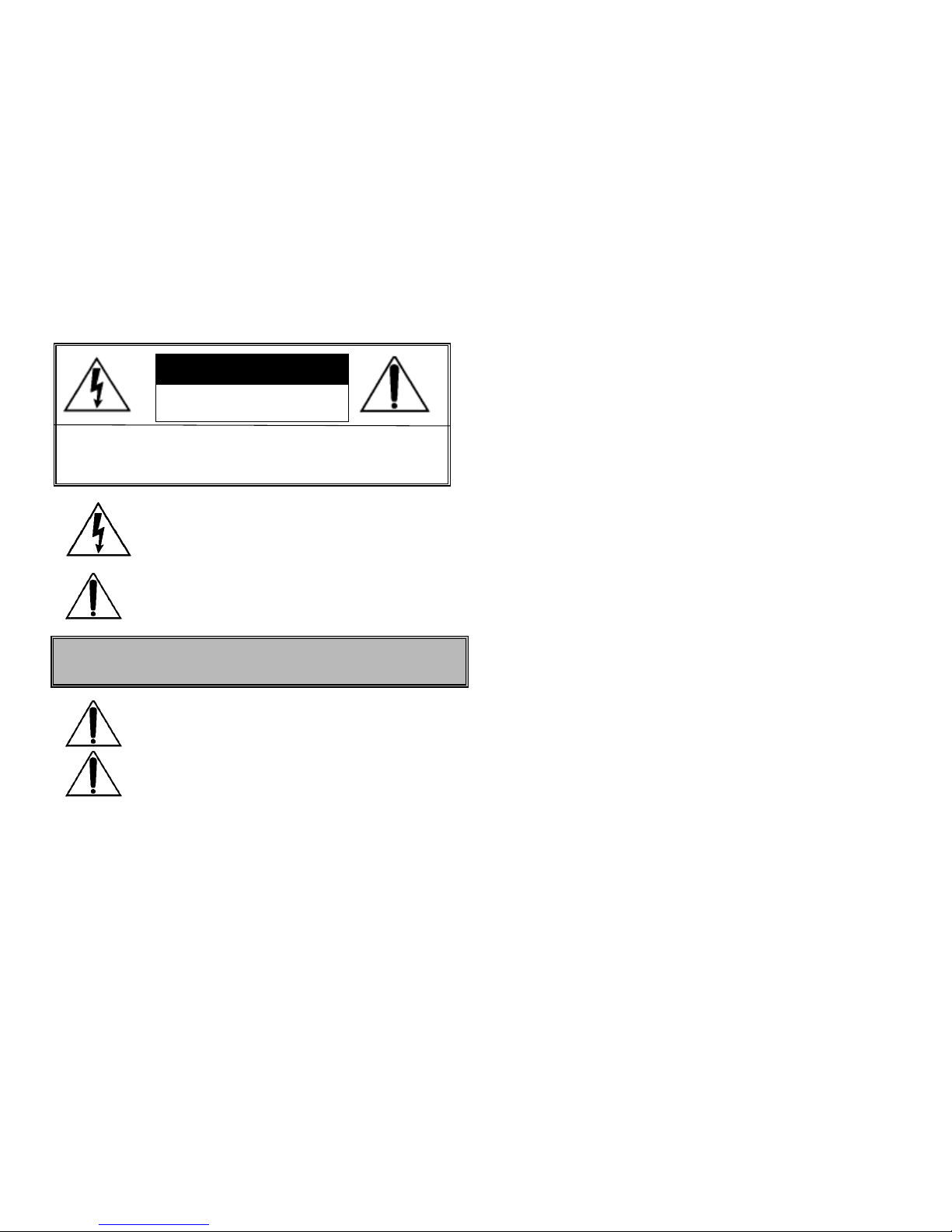
The lightning flash within equilateral triangle means the
presence of insulated “dangerous voltage” within the product’s
enclosure that may be of sufficient risk of shock to users.
The exclamation point within the equilateral triangle is intended
to alert the user to the presence of important operating and
maintenance instructions which can be found in the users’
manual.
Warning: the installation must be done by qualified personnel
according to what established by national rules.
Power off. The power supply is powered even when the device
is switched off and the plug is in the socket. Nevertheless the
device works only when the switch is in ON position ( I ).
The product has been tested and found to be compliant to rules for CE
marking.
Index
Introduction to Digital Video Recorder
Front panel buttons
Rear panel
DVR installation
Video output connection
Video input connection
Sensor installation
Installation with external alarm systems
Power up the unit
On Screen Display
Main menu
Camera select
Channel display control
Record select
Record mode
Record frame rate
Record frame rate table
Video quality
Different video quality settings and HDD capacity
Record time table: EACH mode
Record schedule
Sensor recording installation
Sub menu
Password change
Time set
Date display format
Backup through ISB port
Sequential time
HDD setup
Sensor setup
Sensor setting notes
How to operate motion detection recording
Playback
DVR PC viewer (via USB cable)
How to operate PC viewer
PC Viewer
Technical specification
Introduction to Digital Video Recorder (DVR)
The digital video recorder (DVR) is for recording video streams from up to 4
channels at the same time. It adopts a digital image compression technology to
compress the input channel video streams, and uses HDD to record the
compressed video stream.
The following operation guide explains how to operate/manage the DVR, and
the following installation guide explains how to install DVR at your home or
HDD into the DVR.
WARNING: TO AVOID THE RISK OF FIRE OR ELECTRIC SHOCK DO
NOT EXPOSE THE DEVICE TO WATER, RAIN OR HIGH
HUMIDITY OR HIGH TEMPERATURE.
WARNING: TO REDUCE RISK OF ELECTRIC SHOCK DO NOT
REMOVE THE COVER. NO USER SERVIC EABLE P ARTS ARE. REFER
SERVICING TO QUALIFIED SERVICE PERSONNEL.
WARNING
RISK OF ELECTRIC SHOCK
DO NOT OPEN!
Page 3
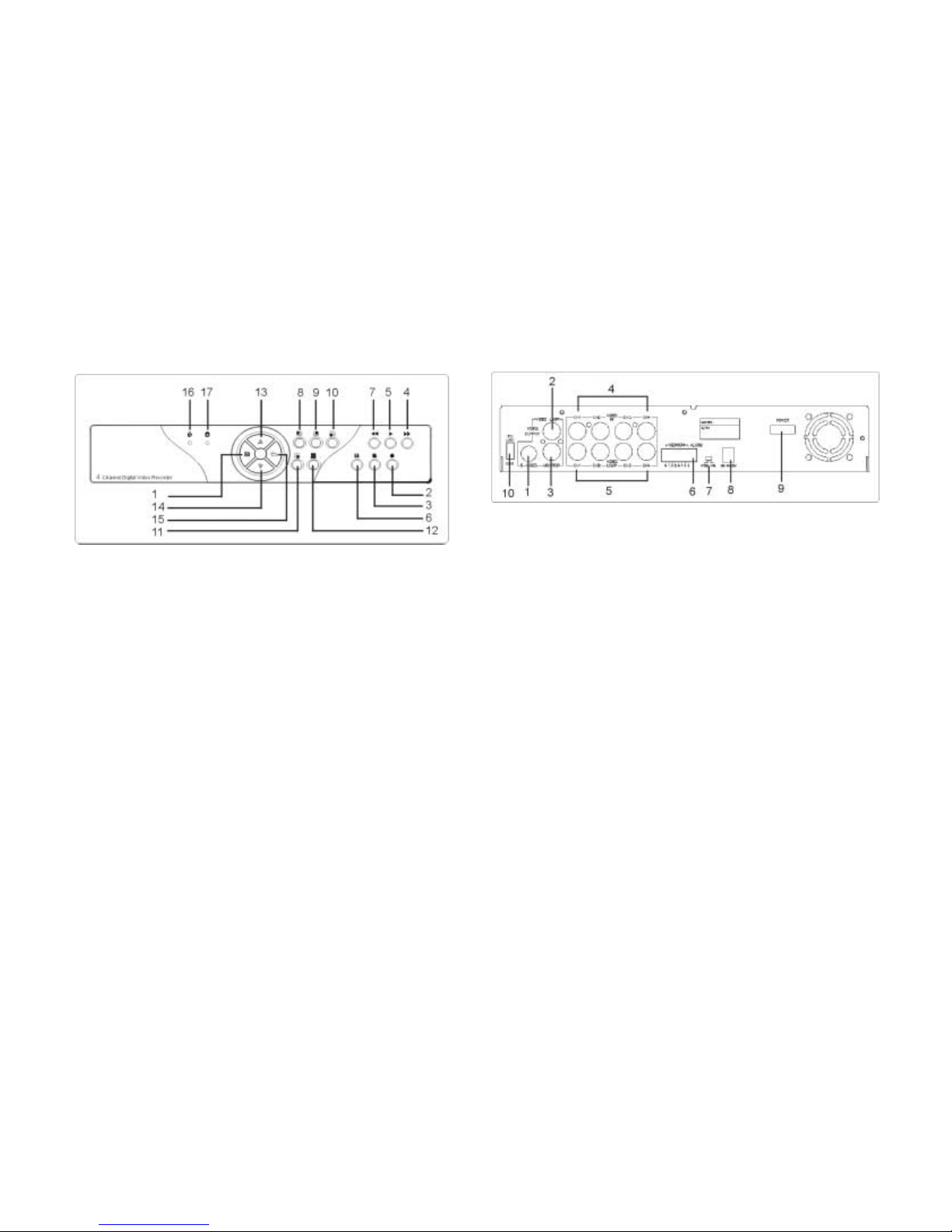
Front panel buttons
1. ! (Menu) button: press to display Operation menu option.
2. ! (Recording button): press to start recording.
3. " (Stop recording/playback button):press stop recording/playback
(the authorized password is requested upon stopping record;
the default password is 111111).
4. ! (Fast forward button): press to play the recorded stream faster.
5. ! (Playback button): press to start playback.
6. " (Pause button): press to pause the video playback.
7. # Reverse: press to playback backward.
8. Channel 1 button: press to select channel 1.
9. Channel 2 button: press to select channel 2.
10. Channel 3 button: press to select channel 3.
11. Channel 4 button: press to select channel 4.
12. All channels button: press to select all channels display.
13,14. $% up down buttons: press to change menu field.
15. (Select) button: Cyclic function. Press to change the setting value or enter
into a sub menu.
16. Power ON LED indicator.
17. Recording LED indicator.
Rear panel
1. S-Video output
2. Composite video output
3. Monitor: Secondary Video output
4. Video input
5. Video loop-through
6. Sensor input/alarm output: 4 sensor inputs and one alarm output
7. NTSC/PAL switch
8. DC-in (12Voltage)
9. Power switch
10. USB 2.0 link to PC
Notices:
- Before powering the system, check that the video system selector is properly
switched to the standard (NTSC/PAL) used.
- To avoid noise and bad images it is very important to run 75Ω coaxial cable
between cameras, DVR and monitor. Choose the correct kind of cable
according to distance and avoid to run video signal cables together with mains
cables.
- Use only 75 Ω BNC connectors for each cable to respective video input and
pay attention during their installation. Many times not proper functioning,
noises and low quality images are due to bad connections.
- Always switch off the DVR before change any connection.
- To avoid HDD from loose data, stop recording before switch off the
DVR
.
Page 4
DVR installation
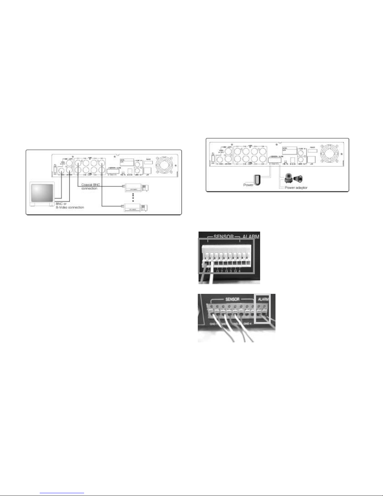
1.Video output connection (Monitor)
Connect monitor to the unit using the Video output connector on the rear
panel.
The unit is equipped with 1 x S-Video output and 2 x BNC connector.
2. Video input connection (Cameras)
Connect up to 4 cameras to the unit using the Video input connectors on the
rear panel.
The unit is equipped with 4 x BNC as input connectors.
Camera installation:
- Video signal line connection: connect the video signal line to the unit using
75ohm coaxial cable and suitable connectors.
- Camera power line connection: connect camera’s adaptor to camera, and
plug in the adaptor.
3. Sensor Installation:
The unit is equipped with 4 sensor input (one for each channel).
- Sensor signal line connection: connect the signal line to the unit. The sensor
signal terminal is usually at the sensor’s back panel.
- Connect a suitable power adaptor into the sensor to power on it
.
There are two kind of sensors:
N.O. (Normally Open): when the alarm signal
is activated, the sensor output is like a short
circuit.
N.C. (Normally Close): when the alarm signal
is activated, the sensor output is like an open
circuit.
Be careful during the installation to choose
the suitable kind of sensor and to setup the
menu accordingly.
4. Installation with external alarm systems:
The unit provides an internal relay
output to activate external devices
such as lamp, sounding devices when
a sensor is activated. The switch Is
open at normal state and, when the
alarm is activated, the switch will be
closed.
- The alarm device is usually provided
with a suitable a power supply.
- Connect the alarm power line
as shown in the above figure to the alarm terminals (max 24Vdc/1A).
Page 5
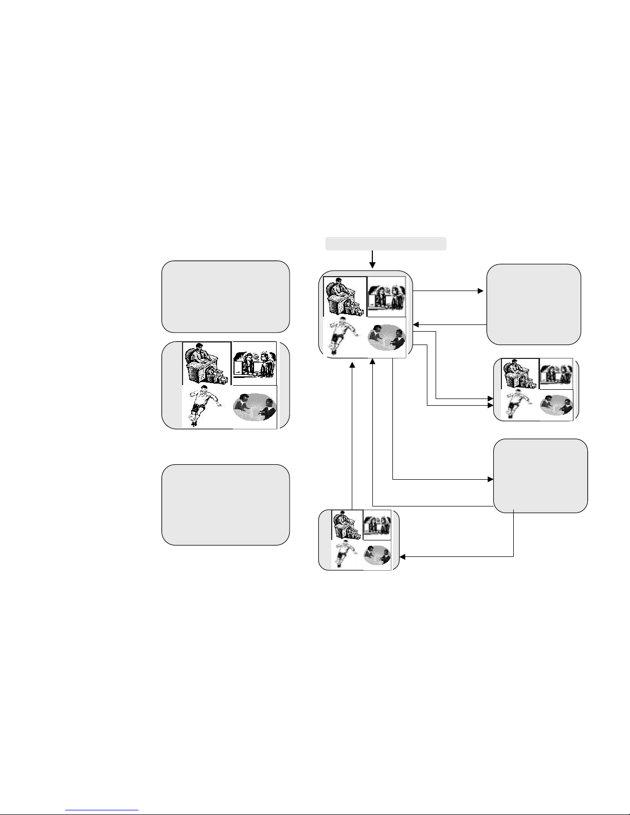
Power up the unit
After the unit is properly installed, the DVR is ready to record and play. Then
apply power supply provided and switch on.
After the unit is powered on, the
unit will check the HDD for
several seconds. The
information shown will be as:
The unit will enter into real-time
display mode shown in the
figure.
Notice:
To resume factory default
settings, push 5 time # button
and the message “Turn off and
on the DVR” will be displayed.
Then to complete the reset
operation, turn off and on the
DVR.
The above procedure will not
delete the images recorded in
the HDD.
The On Screen Display
HDD CHECKING
OK
CH1 CH3
CH3 CH4
Turn off and on the DVR!
Press " button to
stop playback
SEARCH TIME
HDD: MASTER
04/03/24 13:24:21-04/03/24
13:44:54
>01 TIME 04/03/24 13:24:21
>02 TIME 04/03/24 13:30:55
>03 TIME 04/03/24 13:40:54
(#$) MOVE,(" )
CHANGE
,(
!)PLAY
MAIN MENU
CAMERA SELECT 1234
RECORD SELECT 1234
RECORD MODE EACH
RECORD FRAMERATE 25
VIDEO QUALITY HIGH
RECORD SCHEDULE
SUB MENU
HARD DRIVE SETUP
SENSOR SETUP
Press ! button
to display OSD menu
1. Power on the system
●
●●
● CH1 ●
●●
●
Press ! button to exit
OSD menu to real-time
dis
play
Press % button to
start recordin
g
Recording Mode Display
OSD Mode Display
Search Mode
CH1
Playback mode
Press ! button to
search time or event to
playback
Press " button to stop
recording (password is
re
q
uested!
)
Press ! button to exit
the menu
Press ! button to
start playing
CH1
CH3
Page 6
Main menu
Notice
- When main menu is displayed the DVR will not record.
- In order to avoid HDD damages and video data loss, be sure to stop
recording before powering off the DVR.
Camera select
The unit provides 4 camera inputs.
You can use CAMERA SELECT option to
select specified channel for real-time display.
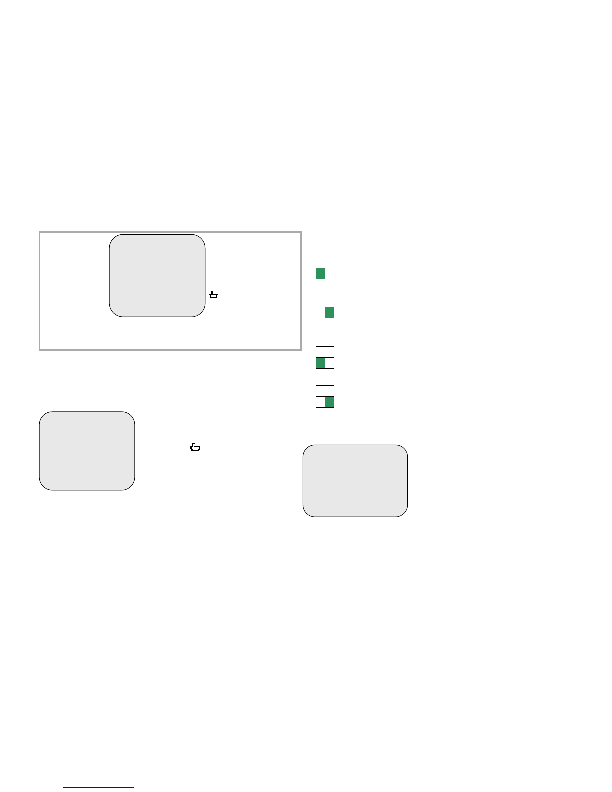
You can use “ ” button or channel buttons
for different combinations for channel display.
1. When you choose (----), all cameras are off.
2. When you choose (1234), all cameras are
displayed.
3. When you choose (---4), only the fourth
channel is displayed.
Notice
- “VIDEO LOSS” message will be displayed, and the built-in alarm buzzer will
be triggered to sound, while one ore more channels are not connected or in
case of connection failure during recording.
- To avoid VIDEO LOSS message and buzzer sound, use CAMERA
SELECT option to select only the channels connected to DVR.
Channel display control
In each mode(EACH) mode, you can use the following buttons to display Fullscreen format of each channel.
Press Select button to activate cyclic display.
Record select
This option allows to enable/disable the
recording of the cameras. Enabling channels
on this menu option using the same way
described in “CAMERA SELECT”.
Cameras will be recorded only if properly
selected in this option.
MAIN MENU
CAMERA SELECT 1234
RECORD SELECT 1234
RECORD MODE EACH
RECORD FRAMERATE 25
VIDEO QUALITY HIGH
RECORD SCHEDULE
SUB MENU
HARD DRIVE SETUP
SENSOR SETUP
Operation Buttons
! --- Press to display menu
option.
#$--- Press to change menu
field or change the unit’s
configuration values.
--- Press to select menu
item or confirm the selection.
Press ! to
display menu
option shown as
right figure
.
& Stop recording or playback before you enter into OSD menu.
&You will be requested to enter password, while stopping recording.
MAIN MENU
& CAMERA SELECT 1234
RECORD SELECT 1234
RECORD MODE EACH
RECORD FRAMERATE 25
VIDEO QUALITY HIGH
RECORD SCHEDULE
SUB MENU
HARD DRIVE SETUP
SENSOR SETUP
Channel 1 button: Full screen display of channel 1.
Channel 2 button: Full screen display of channel 2.
Channel 4 button: Full screen display of channel 4.
Channel 3 button: Full screen display of channel 3.
MAIN MENU
CAMERA SELECT 1234
&RECORD SELECT 1234
RECORD MODE EACH
RECORD FRAMERATE 25
VIDEO QUALITY HIGH
RECORD SCHEDULE
SUB MENU
HARD DRIVE SETUP
Page 7
Record mode
The unit provides 4 camera inputs. You can
use channel buttons on the front panel to
select specified channel for real-time display.
There are two kinds of recording mode.
EACH mode: full screen mode and quad
screen mode can be activated during
recording. Selecting EACH mode during
recording, it is possible to make a playback
even in full-screen of each specific channel
or in quad display.
In this mode the effective frame rate per
each channel is the frame rate set in
RECORD FRAME RATE option divided by
the number of the channel to be recorded.
When you set to QUAD mode, only quad-screen can be displayed during
recording and playback. In this mode maximum record frame rate is 25(30) fps
per each channel.
Use arrow buttons of front panel to select mode and then enter to confirm the
selection.
Record frame rate
There are 6 different frame rate
settings available for operation:
25(30)fps,12(15)fps, 8(10)fps, 6(7)
fps, 4(5)fps, 4fps.
But the DVR is set to 30 fps
NTSC(25fps PAL) as factory default.
Please use #$ buttons of front panel
to select mode and then enter
to select the option.
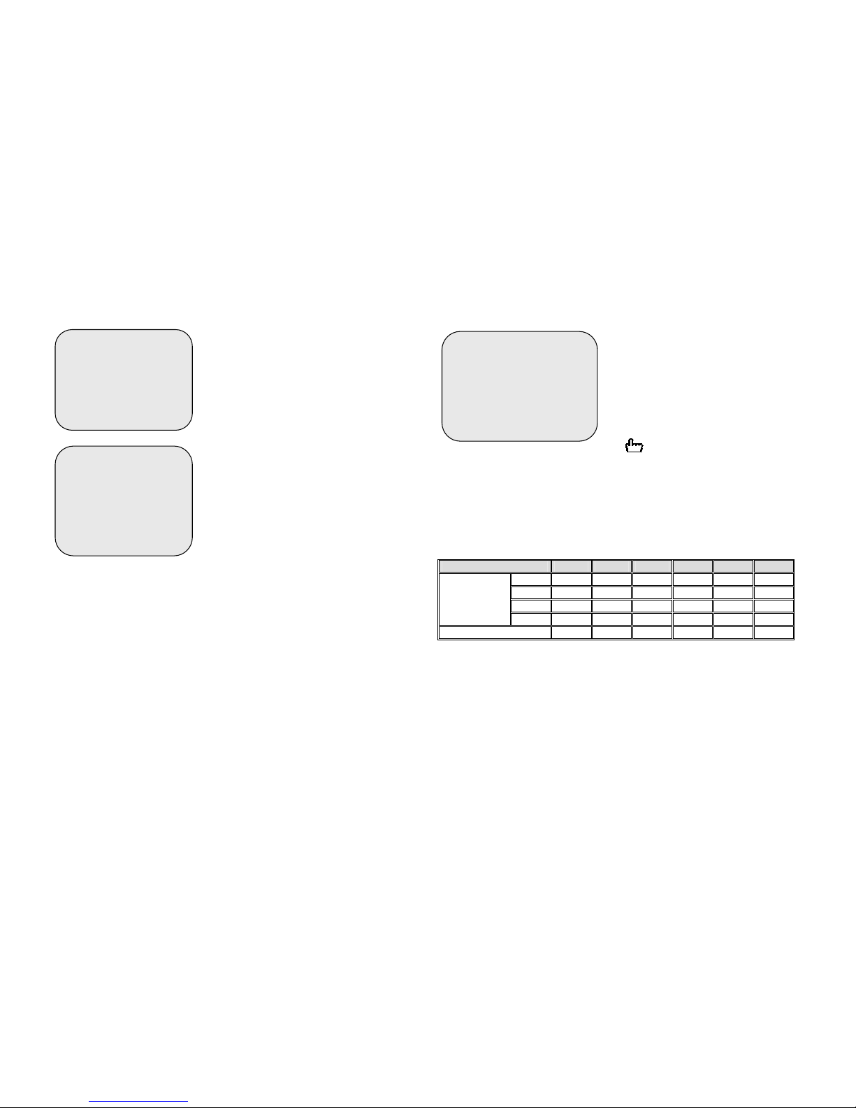
Recording frame rate table
The higher the record frame rate is, the more natural look will be displayed on
the screen on playback mode.
But the lower the record frame rate is, the more you can save the space on
HDD.
The following is the recording fps table for user’s reference.
Frame/second
4 5 7 10 15 30
1 CH 4 5 7 10 15 30
2 CH 2 2.5 3.5 5 7.5 15
3 CH 1.33 1.7 2.33 3.33 5 10
EACH MODE
4 CH 1 1.25 1.75 2.5 3.75 7.5
QUAD MODE
4 5 7 10 15 30
See next section for the HDD duration table.
MAIN MENU
CAMERA SELECT 1234
RECORD SELECT 1234
&RECORD MODE EA CH
RECORD FRAMERATE 25
VIDEO QUALITY HIGH
RECORD SCHEDULE
SUB MENU
HARD DRIVE SETUP
MAIN MENU
CAMERA SELECT 1234
RECORD SELECT 1234
RECORD MODE EACH
&RECORD FRAMERATE 25
VIDEO QUALITY HIGH
RECORD SCHEDULE
SUB MENU
HARD DRIVE SETUP
MAIN MENU
CAMERA SELECT 1234
RECORD SELECT 1234
&RECORD MODE EA CH
RECORD FRAMERATE 25
VIDEO QUALITY HIGH
RECORD SCHEDULE
SUB MENU
HARD DRIVE SETUP
Page 8
Video quality
There are 3 different video quality settings for
operation: Normal, Low and High.
Use #$ buttons of front panel to select mode
and then enter to confirm the selection.
Even video quality affects the total recording
capability on HDD.
Different video quality settings and HDD capacity
The higher the video quality is, the clearer images the unit plays.
The lower the video quality is, the more you can save the space on HDD.
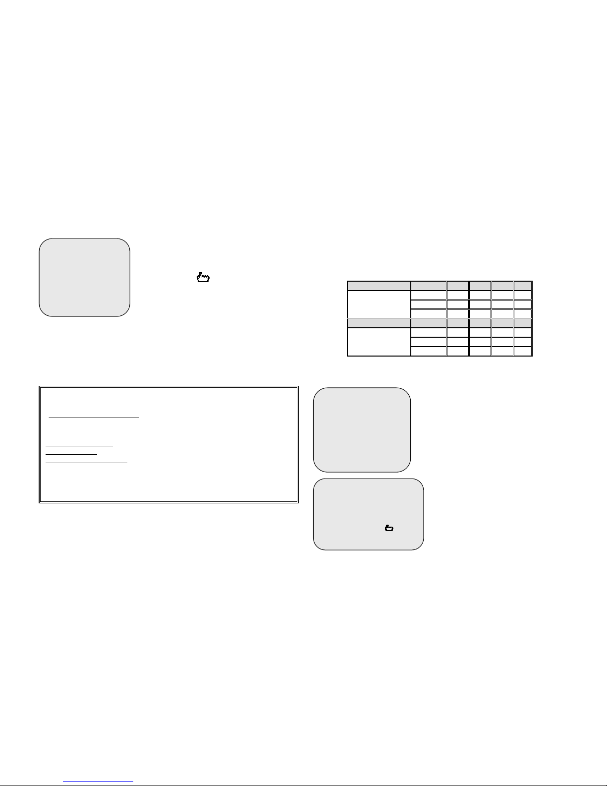
The following table shows the recording time vs video quality settings table
with 80GB HDD for your reference.
Recording Time Table: Each mode
NB: The time table here below is for your reference only. Real HDD duration
will vary depending on the image complexity, color, Black & White, brightness,
contrast, image movement and background video noise. The overall capacity
could be less or more than the figure shown here.
Recording mode ↓ Fps→ 4 8 12 25
HIGH 427H 214H 142H 68H
NORMAL 505H 253H 168H 81H
PAL
LOW 617H 309H 206H 99H
Recording mode ↓ Fps→ 4 7 15 30
HIGH 463H 265H 123H 62H
NORMAL 556H 317H 148H 74H
NTSC
LOW 694H 397H 278H 93H
Record schedule
Enter into this option to change a recording
schedule during a day (24-hour period).
Numbers below indicate the time
duration within the 24 hours.
(T) Letter indicates recording.
(S) Letter indicates sensor recording. It
means the unit starts recording as the
attached sensors being triggered
during this period.
(--) Recording is off during this
duration.
MAIN MENU
CAMERA SELECT 1234
RECORD SELECT 1234
RECORD MODE EA CH
RECORD FRAMERATE 25
&VIDEO QUALITY HIGH
RECORD SCHEDULE
SUB MENU
HARD DRIVE SETUP
Recording time calculation formula:
)(secRe
sec)/)((
)/(000.000.1)(
ondsecordingtim
kBxC
GBkxGBA
= , where:
A: Hard disk capacity
B: Video Quality
: Low (9Kb/frame), Normal (11Kb/frame), High (13Kb/frame)
C: Recording Frame Rate
: 25fps, 12fps, 8fps, 6fps, 4fps, 3fps, 2fps, 1fps.
Example: Continuous recording with High quality and Max. 25fps with 80GB
HDD. (80GB x 1,000,000 k/GB)/ (13k/f x 25fps) k/sec = 246.153,67 sec
246.153,67sec/60 = 4.102,5min. 4.102,5min./60 = 68,37hrs 68,37hrs/24=
2,85 days(continuous recording time for 80GB).
MAIN MENU
CAMERA SELECT 1234
RECORD SELECT 1234
RECORD MODE EACH
RECORD FRAMERATE 25
VIDEO QUALITY HIGH
&RECORD SCHEDULE
SUB MENU
HARD DRIVE SETUP
SENSOR SETUP
PROGRAMMED RECORD
+ T T T S S T T T T T T T T T +
0 3 6 9 12 15 18 21 24
PRESS (#$), THEN ( )
PRESS(! ) TO EXIT
Page 9
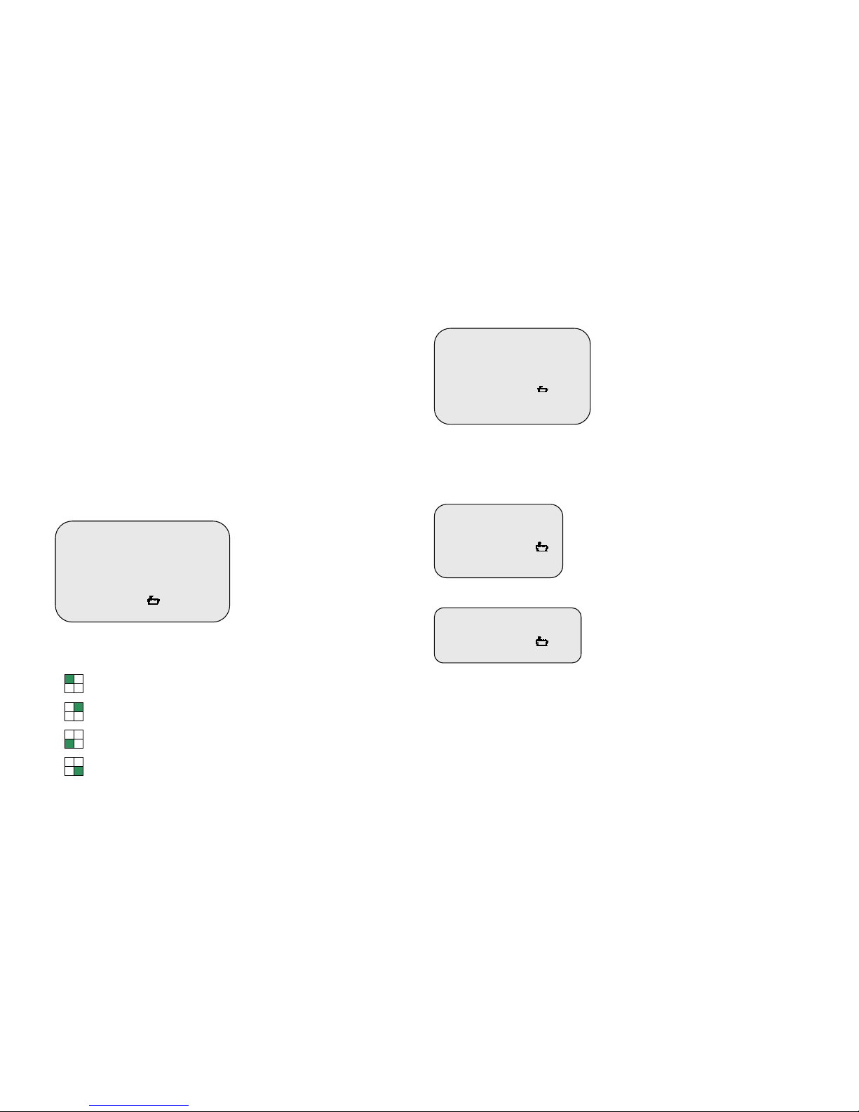
SETTING EXAMPLE:
0:00 ~ 7:00 SENSOR RECORDING
7:00 ~11:00 RECORDING DISABLED
11:00 ~18:00 RECORDING
18:00 ~24:00 SENSOR RECORDING
+ S S S S S S - - - - T T T T T T T S S S S S S +
: : : : :
0 6 11 18 24
Sensor recording installation
The unit provides 4 alarm inputs that can be configured as normally close
(+NC), normally open (+NO), on “SENSOR SETUP” menu option. (Please
refer to sensor setup section). After sensor configuration, please go back to “
RECORD SCHEDULE” menu to enable sensor recording.
Sub menu
Enter into this option to change
password, time /date setting, date
format, enable the connection between
the unit and PC over USB interface
and setting CH sequential Time 1~9
sec. (in each or quad press enter
button to set sequential dwell time)
.
NOTICE
The password can be only numerical (1-4) and up to 6 digit, use the following
buttons to input:
Means 1
Means 2
Means 3
Means 4
Password change
Enter into “PASSWORD CHANGE”
menu and the password change input
menu replaces the “SUB MENU” (The
default password is 111111).
When the new password is accepted,
the board will flash the following
screen message:
PASSWORD changed!!!
The message will blink 5 times. Then the display goes back to SUB MENU.
If the password was not accepted, the unit will automatically return to SUB
MENU.
Time set
Enter into this option to adjust date
and time.
Date display format
The unit can display the date in two
format yyyy/mm/dd or dd/mm/yyyy
variant which depends on the regional
preference.
IMPORTANT NOTICE
Data and time are used to store and to search images in the HDD. Be sure to
set this information properly to avoid malfunction.
As periodical checking it is suggested to verify that date and time are properly
adjusted.
SUB MENU
&PASSWORD CHANGE
TIME SET
DATE DISPLAY MODE YYYY/MM/DD
LINK TO PC
SEQUENTIAL TIME 1
PRESS (#$), THEN ( )
PRESS
(
! ) TO EXIT
PASSWORD CHANGE
CURRENT PASSWORD: ------ NEW PASSWORD:------ PASSWORD CONFIRM:--------
PRESS (#$), THEN ( )
PRESS(! ) TO EXIT
TIME
2004/03/21 03:23:21
PRESS (#$), THEN ( )
PRESS(! ) TO EXIT
DATE DISPLAY FORMAT
PRESS (####$$$$), THEN ( )
PRESS(! ) TO EXIT
Page 10
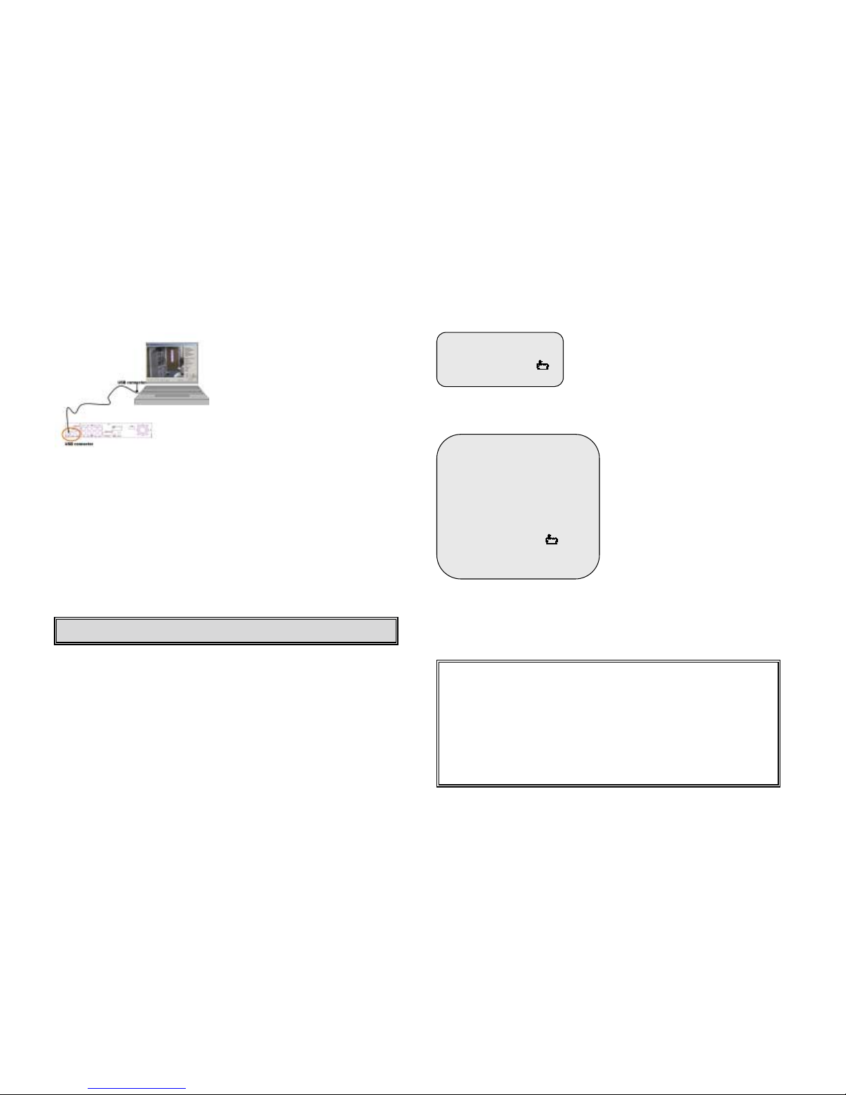
Backup through USB port
The unit provides one USB port to simple
backup over the connection with PC.
Please mind the following steps to
successful link.
Step 1. Connect the USB cable between
the unit and PC.
Step 2. Select “LINK TO PC” under
submenu of the unit.
Step3. The “linking” will take around
30sec.
Step4. The connection is ready for PC backup as “Linked” indicates on the
screen.
Step 5. Open the PC viewer on PC, once PC identifies one unknown Hardware
device. Follow the instructions at DVR PC VIEW ER section to make the
backup.
Step6. Press ”Menu” button back to “Main Menu”.
NOTICE
1. The unit employs USB 2.0, so it will take around 5 min to hand shake with
USB 1.0.
2. Before operating backup over USB, please install PC viewer software into
your PC.
Sequential time
Use this menu to specify each channel display
dwell time.
Dwell time settings determine from 1 sec to 9
sec between displays for 4 channels.
To display images with cyclic switcher, press
Select button in live mode.
HDD setup
OVERWRITE ENABLED:
If you choose “YES”, the unit will
continue recording and overwrite the
recorded data when HDD’s space is
full.
If you choose “NO”, the unit will stop
recording while HDD’s space is full.
MASTER HDD SIZE:
It indicates the capacity of the primary
HDD installed in the unit
MASTER HDD USED:
It indicates how percentage of HDD’s
capacity has been occupied.
MASTER HDD FORMAT:
It erases all of the recorded data in Master HDD.
The authorized password is requested before formatting, after the unit
formatted, the following information will appear on the screen “HARD DISK
FORMATTED”.
Warning: Please don’t press “MENU” button during linking status, it would likely
lead to un
p
redictable Error on your PC.
Overwrite: When the hard disk is full, the DVR will overwrites and
creates new video file gradually. The new created video equals
overwrited portion. When Overwrite function starts, it does not erase the
whole video file(s) of a hard disk at one time.
When there is a new hard drive, the "HDD OWRT “xx%" represents the
% of the hard drive used.
If OVERWRITE recording mode is enabled, the "HDD OWRT “xx%"
represents the xx% of the hard drive that has been overwritten for new
video data. The remaining % (old video data) still exists.
HARD DRIVE SETUP
OVERWRITE ENABLED YES
MASTER HDD SIZE 40000MB
MASTER HDD USED 0MB 0%
MASTER HDD FORMAT
PRESS
(#$), THEN ( )
PRESS(! ) TO EXIT
SEQUENTIAL TIME
PRESS (#$), THEN ( )
PRESS(! ) TO EXIT
Page 11
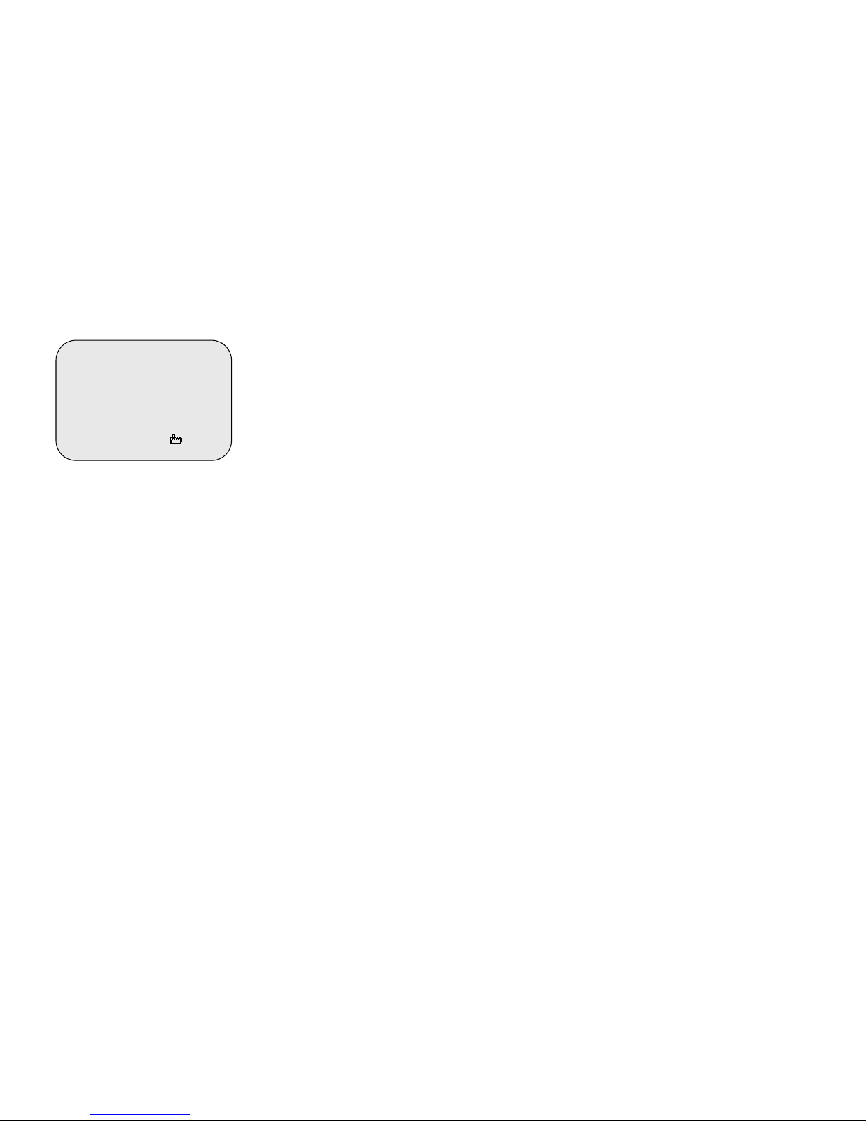
Sensor setup
SENSOR RECORD TIME:
Recording duration once sensor being
triggered.
ALARM OUT TIME:
It controls how long ( in second) the
alarm sounds after being triggered.
SENSOR TRIGGER MODES:
The unit provides 5 different modes for
variant uses:
1.Not installed.
2. Normal open.
3. Normal close.
4. Motion +N-C
5. Motion + N-O
In normal close mode, if the cable line connected between the sensor and the
DVR is cut off by an intruder, the unit will start recording.
In normal open mode, the cable line connected between the sensor and the
unit is cut off by an intruder, the unit will not start recording.
Sensor setting notes:
1. After “sensor/alarm” installation, come back to “RECORD SCHEDULE” to
select “S” (sensor record) as record mode in the specified period of time.
The unit will accordingly start recording upon alarming during the specified
time.
If finished the sensor and alarm hardware setting. Please press “● “button on
the DVR front panel. Then the DVR will enter the record “stand-by” mode.
Each sensor input corresponds to each camera:
Sensor input #1 corresponds to camera #1.
Sensor input #2 corresponds to camera #2.
Sensor input #3 corresponds to camera #3.
Sensor input #4 corresponds to camera #4.
To trigger multiple cameras for alarm recoding simply wiring one sensor to
multiple sensor inputs.
2. SENSOR RECORD TIME:
This function is setting how long recording will be stop after the alarm symptom
disappear. If alarm symptom didn’t disappear, recording won’t stop.
Is it possible to set one of the following choices: 5s, 10s, 15s, 20s, 25s and 30s
(seconds).
3. ALARM OUT TIME:
This function is setting how long alarm out will be stop after the alarm symptom
disappear. If alarm symptom didn’t disappear, alarm out won’t stop.
Is it possible to set one of the following choices: 0s, 5s, 10s, 15s, 20s, 25s,
30s and CONT (continues).
4. MOTION SENSITIVE SETUP:
Use this option to adjust the Motion sensitiviy. There are 9 step of sensitivity: 1
more sensitive, 9 less sensitive.
5. There are 5 different mode for sensor setting:
NOT INSTALLED, NORMAL-CLOSE, NORMAL-OPEN, MOTION+NO and
MOTION+NC:
CHANNEL-1 TYPE: NORMAL-CLOSE
CHANNEL-2 TYPE: NORMAL-OPEN
CHANNEL-3 TYPE: MOTION+N-O
CHANNEL-4 TYPE: MOTION+N-C
In NORMAL-COLSE mode, if the cable line connected to the sensor through
DVR is cut off by an intruder, the sensor recording start.
In NORMAL-OPEN mode, if the cable line connected to the sensor through
DVR is short by an intruder, the sensor recording start.
NOTE
1. A switch setting on the back panel may be used to convert the operation
format from NTSC to PAL, or vice versa.
2. RESET(Initialization): to make the board to reset. Press “#”. button 5 times
in the normal view mode. Be aware that all the information (including the
password) will be lost. After reset, the password will be set as the default value
(111111)
SENSOR SETUP
SENSOR RECORD TIME 15
ALARM OUT TIME 20
MOTION SENSITIVE SETUP
CHANNEL-1 TYPE:MOTION + N-C
CHANNEL-2 TYPE:MOTION + N-O
CHANNEL-3 TYPE:NORMAL CLOSE
CHANNEL-4 TYPE:NOT INSTALLED
PRESS (#$), THEN ( )
Page 12
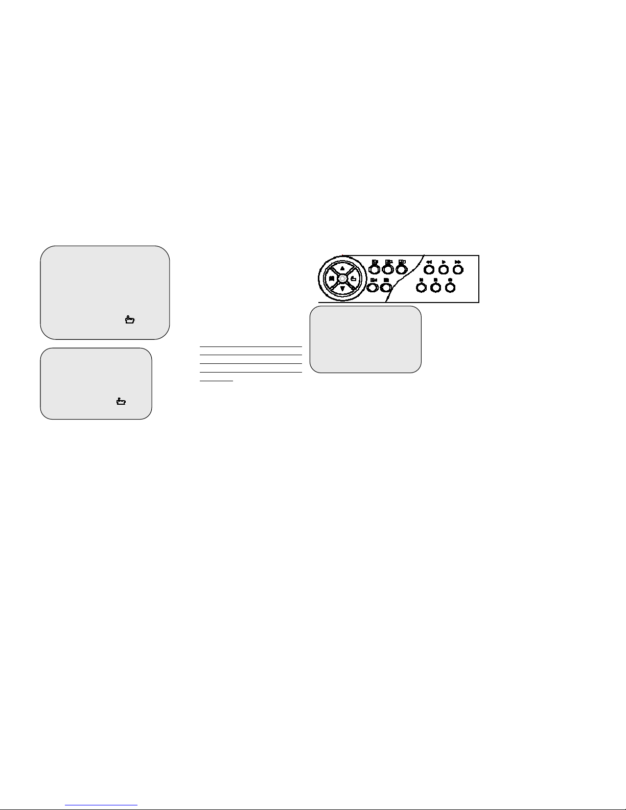
How to operate motion detection recording
Follow the steps as described here
below to activate motion-detection
recording.
1.Please go to “SENSOR SETUP”
menu as the left figure shown.
2. Select out the motion option.
3. After the selection, please be back
to MAIN MENU and come back to
“PROGRAMMED RECORD” to select
the alarm (S) setting.
Notice: The setting under
“PROGRAMMED RECORD” is
necessary for starting the
operation of motion detection
recording.
Playback
Use the front panel buttons to
operate various playback
functions.
Press “►” button, then the
playback time /events
selection menu as the left
figure appears on the screen.
Or you can simply press “►”
twice to directly start playing.
You can either enter the specified time/date to playback or select the event or
even view the playback over PC.
Notice
1. Stop recording before activate a playback.
2. Because the events selection is default setting, so you need to press “►►”
button to switch to time selection.
3. Press “►” button to see new created (by overwriting) files list. (It can list up
to 64 files.) Choose desired video file by moving up/down buttons and press
“►” once again to play.
Press “►►” button to see the whole recorded time range (begin to end)
including any non-overwrited video. If any desired date and time is out of this
time range, there won't be any video exist (means either overwrited or not
recorded). To search desired date and time, press up/down buttons to move
the cursor to the positions of beginning date and time and press Enter button
to change for desired date and time numbers. Then, press “►” button to play.
Control buttons
SENSOR SETUP
SENSOR RECORD TIME 15
ALARM OUT TIME 20
MOTION SENSITIVE SETUP
CHANNEL-1 TYPE:MOTION + N-C
CHANNEL-2 TYPE:MOTION + N-O
CHANNEL-3 TYPE:NORMAL CLOSE
CHANNEL-4 TYPE:NOT INSTALLED
PRESS (#$), THEN ( )
PRESS(! ) TO EXIT
PROGRAMMED RECORD
+ T T T S S T T T T T T T T T +
0 3 6 9 12 15 18 21 24
PRESS (#$), THEN ( )
PRESS(! ) TO EXIT
SEARCH TIME
HDD: MASTER
04/03/24 13:24: 21-04/03/24 13:44:54
>01 TIME 04/03/24 13:24:21
>02 TIME 04/03/24 13:30:55
>03 TIME 04/03/24 13:40:54
(#$) MOVE,( )
Page 13
1.! (Fast Forward button):
Press this button to play the recorded stream faster.
The unit provides five levels of fast forward playback speed:
!1: play one time faster (x1), press “!” button.
!2: play two times faster (x2) than the normal play.
!3: play four times faster (x4) than the normal play.
!4: play thirty-two times faster (x32) than the normal play.
!5: play sixty-four times faster (x64) than the normal play.
2. # (Reverse button):
Press this button to play the recorded stream backward.
Remarks: the reverse playback speed depends on the fps, the number of the
recorded channel, the video quality.
3. " (Pause button) :
Press this button to pause the playback, or to advance one single frame upon
pause mode.
DVR PC Viewer (via USB cable)
In order to display recorded images through a PC, it is required to install the
viewer software in the CD-ROM provided with the unit.
To install the software just copy the program viewer.exe in the PC hard disk
and execute it by double click.
The software will automatically seek for recorded pictures by USB connection
or IDE cable.
Note: this software currently supports Windows2000/XP.
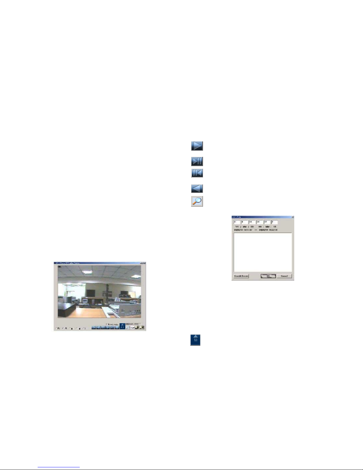
How to operate PC viwer
[PLAY] click the button to start playback from the beginning of the
recorded video.
Button to advance frame by frame forward.
Button to advance frame by frame backward.
[REVERSE] click the button to start playback on backward sense.
[SEARCH] click this button to search video by specific period of
time. Then click <Search events> or fill in data to search.
Page 14
[FAST FORWARD] click to play streams faster (available speeds 1x,
4x, 16x, 32x, 64x).
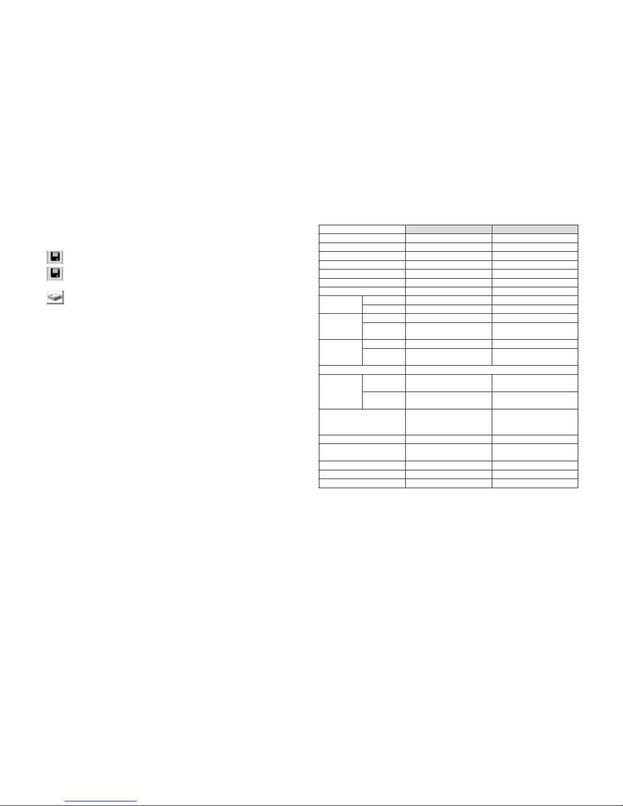
[AVI] Save video in .avi format. Click on [AVI] button and specify the
path and name of the saved file. Click again to disable .avi file saving.
[BMP] Save current image into .bmp file. To save an image, click
Pause button before, then click on [bmp] button.
[Select DVR HDD] HDD selection, click this button to select HDD
among multiple devices installed.
Technical specification
Description Remarks
Video input format
NTSC/PAL
Operating system
None
Video input channel
4ch BNC
Video output
2 BNC + 1 S-Video
Video loop-thruogh
4ch BNC
Alarm in/out
4 input / 1 output
Built-in buzzer
On board
NTSC
120fps 4x30fps
Display
frame rate
PAL
100fps 4x25fps
NTSC
Max 30fps
Recording
frame rate
(QUAD)
PAL
Max 25fps
NTSC
Max 7.5fps
Recording
frame rate
(EACH)
PAL
Max 6.5fps
Recording mode
Continuous, manual, event, programmed
Display
NTSC: 720X480
PAL720X576
Resolution
Recording
NTSC: 640X224
PAL: 640X272
Compression format
Modified MJPEG each
recording
(approx 8-12KB/frame)
Low: 8KB/frame
Normal: 10KB/frame
High: 12KB/frame
HDD
1 internal
Search mode
Time, date, camera,
event
Dimension
290x22x60mm
Weight
2Kg
Certificate
UL, CUL, LVD, FCC,CE
 Loading...