

Page 1
TID-320/ TID-320T
In-Dash 3.2” Monitor
Touch Sensor
DVD/MP4/CD
MW/FM Radio
Built-in NTSC tuner
Owner’s Manual
Take the time to read through this owner’s manual.
Familiarity with installation and operation procedures will help you obtain the best
Performance from your new DVD-receiver.
Page 2

Table of Contents
Table of Contents.......................................................................................................................1
Important Safeguards.................................................................................................................2
Accessories .......................................................................................................................3
Installation/Un-Installation ..............................................................................................................4
Wiring Connections..............................................................................................................................5
Detachable Control Panel ........................................................................................................6
Panel Controls……………..........................................................................................................6
IR Remote Controls ........................................................................................................................8
General Operations....................................................................................................................9
Digital Tuner...................................................................................................................................11
Memory Card/ USB Operations....................................................................................................... 12
Disc operations...............................................................................................................................14
MP3 overview......................................................................................................................................17
TV Operations.....................................................................................................................................18
Compatible Files ................................................................................................................................ 19
SETUP Menu ...........................................................................................................19
Other Functions...................................................................................................................................21
Anti-theft system.................................................................................................................................21
Note on Discs......................................................................................................................................22
Troubleshooting Guide ..............................................................................................................23
Specification.............................................................................................................................24
Page - 1
Page 3

Important Safeguards
z Using the device at temperature below -10℃ may cause the breakage of the device. BEFORE
USING PLEASE HEAT UP THE PASSENGER COMPARTMENT TO THE RECOMMENDED
TEMPERATURE!
z Read carefully through this manual to familiarize yourself with this high-quality sound system.
z Disconnect the vehicle's negative battery terminal while mounting and connecting the unit.
z When replacing the fuse, be sure to use one with an identical amperage rating. Using a fuse with a
higher amperage rating may cause serious damage to the unit.
z DO NOT attempt to disassemble the unit. Laser beams from the optical pickup are dangerous to
the eyes.
z Make sure that pins or other foreign objects do not get inside the unit; they may cause
malfunctions, or create safety hazards such as electrical shock or laser beam exposure.
z If you have parked the car for a long time in hot or cold weather, wait until the temperature in the
car becomes normal before operating the unit.
z DO NOT open covers and do not repair yourself. Consult the dealer or an experienced technician
for help.
z Make sure you disconnect the power supply and aerial if you will not use the system for a long
period or during a thunderstorm.
z Make sure you disconnect the power supply if the system appears to be working incorrectly,(e. g,
making unusual sounds, smelling strange, emitting smokes from inside or liquid having gotten
inside it) Have a qualified technician check the system.
z The unit is designed for negative terminal of the battery, which is connected to the vehicle metal.
Please confirm it before installation.
z Do not allow the speaker wires to be shorted together when the unit is switched on. Otherwise it
may overload or burn out the power amplifier.
z Do not install the detachable panel before connecting the wire.
z Don't remove the detachable panel when encoding.
Page -2
Page 4

Accessories
Package contains the following accessories for installation and operation of the unit.
(1) Washer, Spring
Washer, M5 Nut
1 each
(2) Mounting Strap 1
(3) Screw 1
(4) Bolt 4
(5) Mounting Collar 1
(6) Release Key 2
(7) Rubber Cushion 1
AV in Cable Panel Carrying Case
Owner’s Manual Remote Controller
Page - 3
Page 5
Installation/Un-Installation
First complete the electrical
connections, and then check
them for correctness.
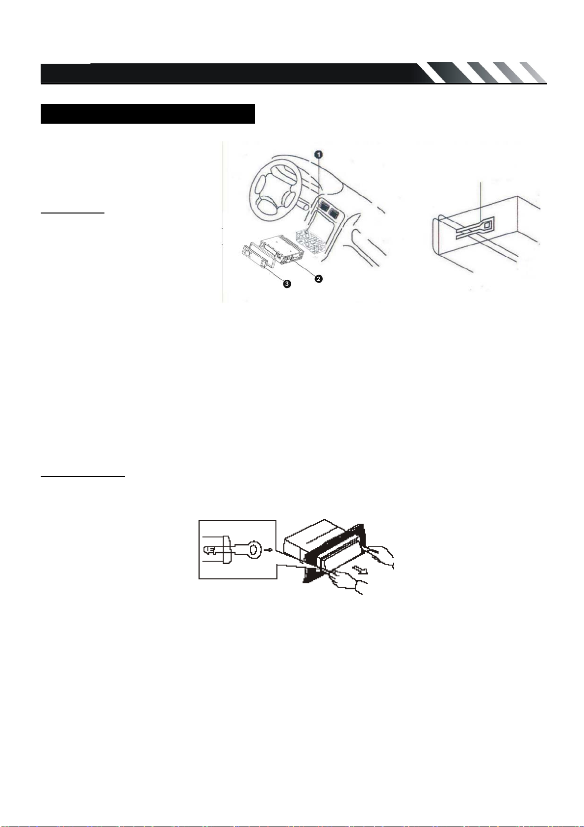
Installation
This unit can be installed in any
dashboard having an opening
as shown on the picture. The
dashboard should be 4.75 –
5.56 mm thick in order to be
able to support the unit.
1. Insert mounting collar into the dashboard, and bend the mounting tabs out with a screwdriver.
Make sure that lock lever(
2. Secure the rear of the unit.
After fixing mounting bolt and power connector, fix the rear of the unit to the car body by rubber
cushion.
3. Insert trim plate.
When you prepare to insert trim plate, please check its direction. Once it was up side down, it cannot
be fixed.
※)is flush with the mounting collar (not projecting outward).
Un-installation
Remove Trim Ring and insert Release Keys into left and right side-end holes as shown in below
picture and pull the unit out of the dashboard.
Lock lever(※)
Page -4
Page 6
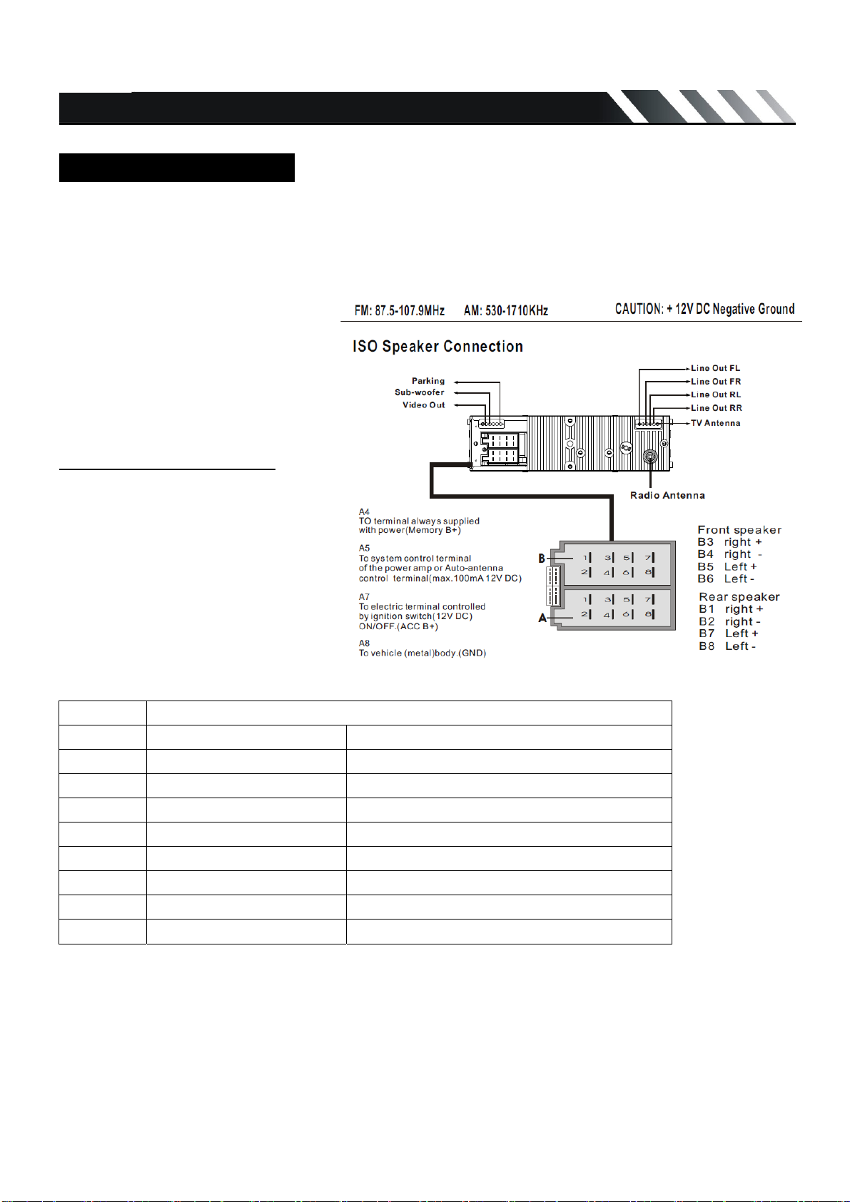
Wiring Connections
Make sure you have good chassis ground. A good ground connection will eliminate most electrical
noise problems. A good chassis ground requires a tight connection to the vehicle’s metal chassis.
The area around the ground connection should be clean, bare metal without rust, paint, plastic, dust,
or dirt for a good electrical connection.
**TV Antenna is for TID-320T only.
Caution: Do not interchange the
connection of the wiring!!!
For some car models you may need
to modify wiring of the supplied
power cord. Contact your authorized
car dealer before installing this unit.
Using the ISO Connector
1. If your car is equipped with the
ISO connector, then connect the
ISO connectors as illustrated.
2. For connections without the ISO
connectors, check the wiring in the
vehicle carefully before connecting,
incorrect connection may cause
serious damage to this unit.
3. Cut the connector, connect the
colored leads of the power cord to
the car battery as shown in the color code table below for speaker and power cable connections.
Location Function
Connector A Connector B
1 Rear Right(+)---Purple
2 Rear Right(-)---Purple/Black Stripe
3 Front Right(+)---Grey
4 Battery 12V (+)/yellow Front Right(-)---Grey/Black Stripe
5 Auto Antenna/blue Front Left(+)---White
6 Front Left((-)---White/Black Stripe
7 ACC+/red Rear Left(+)---Green
8 Ground/black Rear Left(-)---Green/Black Stripe
Page - 5
Page 7
Detachable Control Panel
Detaching the control panel
z Turn the Power off.
z Press OPEN button release the panel.
z Pull the panel out.
Attaching the control panel
z Insert the left side of the control panel into the main unit.
z Press the control panel right side until the “click” sound is heard.
Caution:
DO NOT insert the control panel from the right side. It can damage the control panel.
The control panel can easily be damaged by shocks. After removing it, place it in a protective case
and be careful not to drop it or subject it to strong shocks.
The rear connector that connects the main unit and the control panel is an extremely important part.
Be careful not to damage it by pressing on it with fingernails, pens, screwdrivers, etc.
Note:
If the control panel is dirty, wipe off the dirt with soft, dry cloth only. And use a cotton swab soaked in
isopropyl alcohol to clean the socket on the back of the control panel.
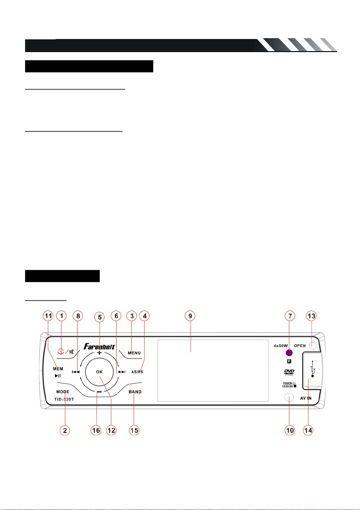
Panel Controls
Front panel
Page -6
Page 8
1. POWER/ MUTE
2. MODE
3. MENU
4. AS/PS
5. Volume Up (+)
6. NEXT
7. IR sensor
8. PREVIOUS
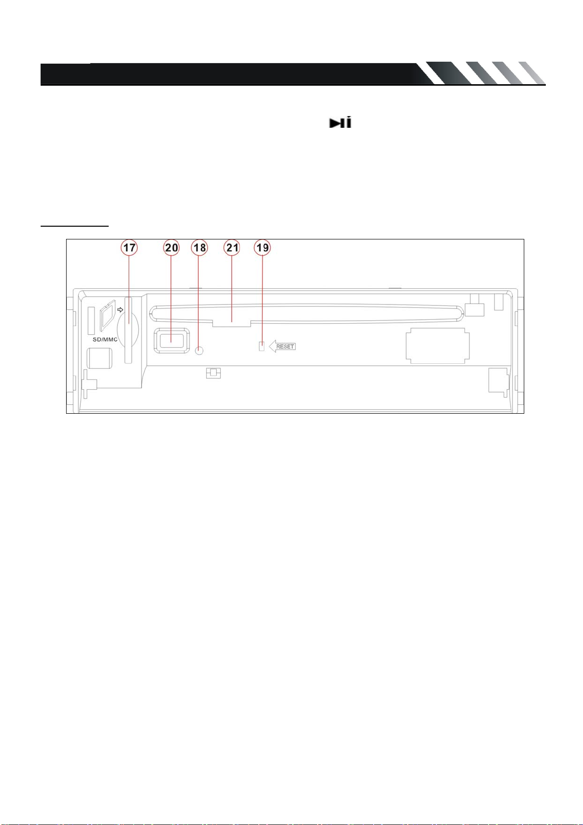
Inner Panel
9. LCD
10. AV in jack
11. MEM/
12. OK
13. OPEN
14. USB jack
15. BAND
16. Volume Down (-)
17. Memory Card slot
18. Flash LED
19. RESET
20. Eject button
21. Disc slot
Page - 7
Page 9

IR Remote Control
1. MODE
2. POWER
3. BND/RDM
4. ENTER
5. Cursor
6. STEREO/MONO
7. LOC/ PROG
8. P.SCN/RPT
9. SEEK-/
10. LOUD
11. OSD
12. STOP/ PBC
13. Digit 0-9
14.
15. MUTE
/ / /
REPLACING THE BATTERY
Remote Control comes with a CR-2025 Lithium Battery included.
1. Remove the Battery Holder from the back of the Remote Control.
2. Insert a CR-2025 Lithium battery with the positive (+) mark upward. Insert the Battery Holder into
the back of the Remote Control.
16. MENU
17. SUB-T
18. SETUP
19. ANGLE
20. INT
21. VOL+
22. A-B/ZOOM
23. SEL
24. SEEK+/
25. VOL-
26. AUDIO/ GOTO
+3V
(CR 2025)
Warning: Store the battery where children cannot reach. If a child accidentally swallows the battery,
consult a doctor immediately.
Do not re-charge, short, disassemble or heat the battery or dispose it in fire.
Do not expose or bring into contact the battery with other metallic materials. Doing this may cause the
battery to give off heat, crack or start a fire.
When throwing away or saving the battery, wrap it in tape and insulate; otherwise, the battery may
give off heat, crack or start a fire.
Page -8
Page 10

General Operations
Reset the Unit
In case the unit is malfunctioned or need to reset to factory default setting, press RESET button in
inner panel then the unit will be reset.
Power on/off
Press “POWER” button to turn on the unit.
Long press POWER button on front panel or press POWER button on RC to power off the unit.
Mode Setting
Press MODE button on front panel or remote control to change mode in a sequence of:
Tuner =>DVD =USB => Memory Card =>TV=> AV IN=> Tuner
(When DVD/USB/ Memory Card available.)
Menu button
Press to enter MENU setting. Long Press Menu button on remote control can back to Main Menu.
Band button
In radio mode, press to select FM1-FM2-FM3-MW. In DVD mode, if playback mp3/wma files or
contents of multi folders, press to move cursor
right side, long press to move cursor downside.
OK button
In playing DVD mode, short press to enter and confirm;
In playing Radio mode, short press to enter and confirm;
MEM button
In playing DVD mode, short press to play / pause; long press to stop playing.
In playing Radio mode, short press to select manual storage stations.
Volume Control
Turn the knob on front panel clockwise/ counter-clockwise or press VOL +/- button on remote control
to increase/ decrease the volume level.
MUTE Function
Short press POWER/MUTE button on the panel or press MUTE button on the Remote Control to
mute. Press it again to cancel mute.
Audio Setting
Press SEL button on the Remote Control to select the audio setting:
BASS =>TREBLE => BALANCE => FADER => EQ.
Press
to select the setting item).
Press ENTER button or
item.
/ buttons on remote to select the audio setting item (or press the VOL knob on front panel
button on remote control or OK button on front panel to enter the selected
Page - 9
Page 11

Press
/ buttons on remote to adjust the audio setting data (or press the knob on
front panel to adjust the setting data).
Press SEL button on remote again to save the setting data and return to current mode.
Notes: If turn off the power, all the settings of each mode will be saved.
- If turn off the battery power, all the settings will be clear and become factory default setting.
- If you don’t adjust setting within 3 seconds after selecting the desired setting item, the unit will
automatically return to the current mode.
Menu Settings
Press MENU button on front panel or remote control to enter MENU setting.
During FM mode press the MENU button to enter the setting mode.
Press / buttons on the remote control or press the VOL knob on front panel to select the setting.
Press ENTER button or
Press
/ buttons on remote control or press the knob on front panel to adjust the
setting.
Press ENTER button or button on remote control or OK button on front panel to confirm, press
MENU to return to last settings list.
• In Radio mode short and repeat press the OK button to select these settings:
AUDIO=> EXPERT => CLOCK
button on remote control or OK button on front panel to enter the setting.
• In USB/Memory Card mode short and repeatedly press the OK button to select these settings:
AUDIO => PICTURE => EXPERT => CLOCK
z AUDIO MENU
MENU DESCRIPTION(tuning by left or right arrow)
BASS Support 10 levels. Default level is 0.
TREBLE Support 10 levels. Default level is 0.
BALANCE
FADER
Support 10 levels for each left and right channel. Default is left equal to
right.
Support 10 levels for each front and rear channel. Default is front equal to
rear.
EQ DSP OFF FLAT→CLASSICS→POP→ROCK→DSP OFF
z PICTURE MENU
MENU DESCRIPTION
RED Adjust level of red color. Support 50 levels. Default level is 25.
GREEN Adjust level of green color. Support 50 levels. Default level is 25
BLUE Adjust level of blue color. Support 50 levels. Default level is 25.
BRIGHTNESS Adjust level of screen brightness. Support 50 levels. Default level is 25
CONTRAST Adjust level of screen contrast. Support 50 levels. Default level is 25.
SHARPNESS Adjust level of screen sharpness. Support 15 levels. Default level is 10
SCREEN Adjust screen size: 16:9 →4:3→FULL
COLOR
RESET
Resume color default status. (Select YES or NO by navigation buttons, and
press ENTER button on remote control or OK button on front panel to confirm
“YES”)
Page - 10
Page 12

z EXPERT MENU
MENU DESCRIPTION
DX Set search radio station by DX or LOCAL mode. DX→LOCAL
STEREO Set radio audio at STEREO or MONO mode, STEREO→MONO
BEEP Set press keys‘ sound. 2ND→ALL→OFF
LOUD Set loudness on or off. OFF→ON
SUBWOOFER Set subwoofer ON→OFF
BACKLIGHT Set OSD BACKLIGHT: HIGHT→LOW →MID
OSD COLOR Set OSD COLOR:DARK BLUE→VIOLET→LIGHT BLUE
z CLOCK MENU
MENU DESCRIPTION
CLOCK Set CLOCK display time or not. Off / on.
CLOCK HOUR SET CLOCK 12H/24H
CLOCK ADJUST Set CLOCK ADJUST time
On-Screen Display (OSD)
In USB/ Memory Card/DISC mode, short press to show Memory Card /USB/DISC information on the
display, long press one time to show the current playing track/ played time information, long press
twice to show the current playing track/ remainder time for play, long press again to clear the
information.
Driver Safety Function
Note: To watch video the parking wire should be connected to break signal.
Caution! The parking wire is connected with brake signal; for driving safety, the video programs
should only be viewed after the car is parked. Check and follow your local authority’s regulations
regarding watching video in a car.
Digital Tuner
Note: Memory Card /USB service availability varies with areas. Please understand if Memory Card
/USB service is not available in your area, the following service is not available, either.
Band selection
Press MODE button to select the RADIO mode.
Press the BAND button to select the desired band: FM1=> FM2 => FM3 =>MW
Manual/ automatic tuning
z Manual tuning: press the
manual tuning mode. Press the
select a station downward or upward step by step.
/ buttons on remote control and hold for 2 seconds to enter the
/ buttons on the panel or on the Remote repeatedly to
z Automatic tuning: press the / buttons on the Remote or press / buttons on
front panel and hold for 2 seconds, the automatic search will start. It will play when finds the
station.
Page - 11
Page 13

Preset station 1-6 play and setting
z Play preset station: to play the preset station 1-6, you can press number key 1-6 on remote
control, Preset station setting:
number 1-6 buttons on remote to store the preset station 1-6 or press MEM button on front panel
and rotate VOL knob to select the preset station 1-6 and press OK button to store.
Remark: You can store up to a total of 24 radio stations in the memory (18FM, 6MW).
during manual turning or automatic tuning, press and hold the
AS (Auto Store) / PS (Preset Scan)
AS (Auto Store): In tuner mode, Press the RPT/P.SCN button on the remote and hold for 2 seconds
to store radio station’s with the best reception to the preset buttons automatically.
PS (Preset Scan): In tuner mode, press this button to scan the preset memorized station, each
preset scan for 5 seconds. Press again to stop operation.
Memory Card/ USB Operations
USB Flash Memory
To play MP3/ MP4/ WMA files from a USB flash memory, insert a USB flash memory into the USB
port on the right side of the unit. The unit will start playing MP3/MP4/ WMA files on the USB flash
memory automatically. Or press the MODE button to select USB after pressing POWER button to
turn on the unit.
Memory CARD
To play MP3/ MP4/ WMA files on a Memory CARD, insert the card into the card slot (you should
press the OPEN button on the panel to flip down front panel and insert the card into card slot.) The
unit will start playing MP3/ MP4/ WMA files on the Memory card memory automatically. Or press the
MODE button to select Memory Card after pressing POWER Button to turn on the unit.
PAUSE/ PLAY
Press the PLAY/ PAUSE button to pause the playback. Press the button again to resume.
STOP
Press the STOP button on remote to stop playback. Press the PLAY/ PAUSE button to resume. If the
Memory card or USB is removed, the resume function will be cancelled.
Press the STOP button twice to stop the playback totally. Press the PLAY/ PAUSE button to start
playback from the beginning.
Selecting Tracks
If the MP3/ MP4/ WMA files are stored in the folders on the USB drive or Memory Card, the unit will
start by playing the first song in the first folder. After playing all the files sequentially in the first folder,
the unit will play all the files sequentially in the next folder. The unit will continue playing through all of
the folders on the USB drive or Memory card in this manner. Press the
previous track/chapter. Press the
to select the desired track/chapter.
On front face, press BAND button to move cursor right side for select track, press BAND button and
hold for 2 seconds to move cursor downward for select folders.
to play the next track/chapter. Press the digital buttons (0-9)
Page - 12
button to play the
Page 14

GOTO Function
Long press AUDIO/GOTO button on remote control to show GOTO menu, use 0-9 to input track/ time
to go to directly.
Fast Forward and Backward
Press the / buttons and hold for two seconds to select the fast playing in backward or
forward in 2 times, press and hold for two seconds again for 4times, repeat this operation for 8 times
=> 20 times => play. Press the PLAY/PAUSE button to return to normal playback.
Note: During the Memory card or USB playback when Fast backward or forward gets to the
beginning of the playing another track, it resumes normal playback.
Repeat
Press the RPT button on remote control for REP 1 (repeat the current playing file) => REP DIR
(repeat current folder) => REP ALL (repeat all folders) => REP OFF.
Repeat A-B Function
1. Press A-B button on the remote at the starting point of the section you want to repeat (point A).
2. Press A-B button again at the ending point of the section you want to repeat (point B). Section A-B
repeating starts.
3. Press A-B button again to cancel the A-B repeat function.
Random
Press the RDM button on remote to play all song tracks in random order.
Note: This function is only for audio files.
Intro Playback
Press the INT button on remote to play the beginning of every track for 10 seconds in sequence.
Press again to cancel INT play.
Note: This function is only for audio files.
Programming the Playback
1. Press PROG button on the remote open program menu.
2. Use
3. Press PLAY/ PAUSE button to program play, or move the cursor to select PLAY and press ENTER
4. Move the cursor to CLEAR on program menu, press ENTER button on remote or OK button on
5. Press PROG again to cancel program play.
/ / / buttons to select the program position and use digit 0-9 buttons to select the desired
track.
button on remote or OK button on front panel to play.
front panel to delete the programmed list.
Return Function (For video files and pictures only)
During playback of a video file or picture, press STOP button to return to the file list menu.
Selecting Different Audio Modes (only for MP4 files)
Press AUDIO button on the remote repeatedly to select the audio language.
Page - 13
Page 15

Changing the Subtitle Language (only for MP4 files)
Press SUB-T button on the remote to select the preferred language for sub-title.
ZOOM (only for MP4 files)
Press ZOOM button and hold for 2 seconds on remote to activate zoom function in the following
sequences: ZOOM 2 => ZOOM 3 =>ZOOM 4 => ZOOM 1/2=>ZOOM 1/3=>ZOOM 1/4=>ZOOM OFF.
Rotate Picture (only for picture files)
In picture mode, press / buttons to rotate picture 90 degrees.
System Menu
In USB/ Memory Card mode, press SETUP button on remote to show system menu. Press / / /
buttons to set system data, press this button again to save input data and exit system menu.
Discs operations
Glossary
PBC (Play Back Control)
Play Back Control is a menu recorded on the disc with SVCD or VCD2.0 format. For the discs
contained PBC, it can playback interactive software with the menu displayed on TV. And if the disc
contains still images, it can playback high definition of still image.
Title
The title is the important part of DVD disc. The memory volume of the disc is rather big, that makes
possible to record several films on one disc. For example, if a disc contains three films, they may be
divided into Title 1, Title 2 and Title 3. You can easily use the functions to search.
Chapter
A title can be divided into several blocks, so that every block can be operated as a unit, the unit is
called chapter.
The chapter contains a unit at least.
Track
It is the biggest component of VCD. Generally, every song of Karaoke disc is a track.
Discs for playback
z This unit can play:
DVD/SVCD/VCD/HDCD/MP3/MP4/WMA/CDDA/Picture-CD/JPEG/CD-R/-RW/DVD±R/±RW.
z The following file types are supported:
Audio files: MP3 (*.mp3)
WMA (*.wma)
Video files: MP4 (*.avi, MPEG43.11/4.0/5.0/6.0 and XVID)
MPEG 2(*.vob)
MPEG 1(*.dat)
Page - 14
Page 16

Picture file: JPEG (*.jpg)
z ISO 9660 or ISO 9660 +Joliet format - Max. 30 characters
z Max. Track number is 448
z Max. nested directory is 8 levels
z The max. album number is 99
z The max. length of each track is 99 minutes 59 seconds
z Supported sampling frequency for MP3 disc: 8 KHz to 48 (44.1 KHz preferably) KHz
z Supported bit-rates of MP3 disc are: 32 - 320 kbps (128 kbps preferably).
z Following formats are NOT supported *.ACC, *.DLF, *.M3U, *.PLS, MP3 PRO, files with DRM.
z Open session discs are NOT supported.
Loading a disc
1. Turn the power on.
2. Press the Open button on the front panel to flip it down.
3. Insert the disc with the printed side facing upward into the slot. The panel will be closed
automatically. The DVD mode will be turned on automatically. The monitor will show the disc content.
4. Press Open button on the panel and Eject button inner the panel to eject the disc.
If the disc is not removed for about 10 seconds after reject, the disc will reinserted automatically.
When disc in/out, put front panel at 0 degree to avoid distort the disc.
5 You may also choose the playing mode using the MODE button.
Playing/pausing
To ensure good system performance, wait until the unit finishes reading the disc information before
proceeding.
Press the PLAY/ PAUSE button to start/ pause the playback. In pause mode press it again to resume
the playback.
Stop
During playback press the STOP button on the RC. Playback will be stopped. Press the PLAY/
PAUSE button again to start playback from the position at which it was stopped. If the disc is removed,
the resume function is cancelled.
Press the STOP button twice to finally stop the playback. Press the PLAY/ PAUSE button to start
playback from the very beginning.
Playing the previous/ next track/ chapter
1. During playback press the button to start playing the previous track/chapter.
2. Press the
3. Press the digital buttons (1-9, 0) buttons to enter the desired track/chapter number.
to start playing the next track/chapter.
Speed forward and backward
Long press the / buttons on the panel or press and hold for 2 seconds the or on
the RC to select the speed of fast playing in backward or forward direction: X2, X4, X8, X16, X32
Press the PLAY/PAUSE button to return to normal playback.
Note: During the disc playback when Fast/ Reverse Playback gets to the beginning of the playing
another track, it resumes normal playback.
Page - 15
Page 17

Repeat playback
Press the RPT/P.SCN button on the RC once or more times to repeat the playback:
- For VCD/CD: display appears Repeat Track => Repeat Disc => Off (Some discs do not support this
functions).
- For DVD: display appears Repeat Chapter => Repeat Title => Off
- For File disc: display appears File => Folder=> All => Off
Note: to choose FOLDER repeating and TITLE repeating press and hold RPT button.
Repeat A-B function
1. During playback, press A-B button on the remote control at the starting point of the section you
want to repeat (point A).
2. Press A-B button again at the ending point of the section you want to repeat (point B). Section A-B
repeating starts.
3. Press A-B button again to cancel the A-B repeat function.
Random playback (for CD/VCD/MP3 discs)
During disc playback, press the RDM button on the RC to start random playback of the disc. Press
again to cancel.
Intro playback (for CD/VCD discs)
You can play the beginning of every track for 10 seconds in sequence. Press the INT button on
remote control to start intro play of whole disc. Press again to cancel.
PBC (Playback Control) function (for VCD only)
If you insert a VCD with PBC, playback starts from the beginning of the 1st track automatically.
1. Long press PBC/STOP button to activate interactive menu on screen during playback.
2. If the menu consists of titles, you can select a desired one using the / buttons.
3. The VCD starts playing the selected title automatically or press PLAY/ PAUSE button to confirm
the selected track for playback.
Programming the playback
1. Press PROG button on the RC to enter
program list.
2. Use
enter the number of the desired track to be on
selected position.
For DVD and File disc, select title and chapter
number.
For VCD and CD, select track number.
3. Press PLAY/ PAUSE button to play, or move
the cursor to select PLAY and press ENTER to
play.
4. If you want to delete the list, move the cursor to CLEAR, press ENTER to delete all the list set
before.
5. Press PROG again to exit program play.
, , , buttons and digit buttons to
Page - 16
Page 18

Selecting different audio modes
z For DVD disc: press AUDIO on the RC repeatedly to select the audio language to listen (if the disc
supports multi-language mode).
z For VCD disc: press AUDIO on the RC repeatedly to select the following modes:
L R STEREO (Channel left => Channel right => Stereo).
Changing the subtitle language (for DVD only)
Press SUBTITLE button on the RC to select the preferred language for the disc menu. When the
selected language is recorded on the disc then this language will automatically be selected. If not, the
first language recorded on the disc is displayed.
Changing size
Press and hold for 2 seconds the A-B/ZOOM on the RC. The picture will be enlarged accordingly: X2
=> X3 =>X4 => X1/2=>X1/3=>X1/4X=>Normal.
Changing angle (for DVD only)
If DVD discs support multi-angle playback, press ANGLE on the RC button to playback images in
different camera angles. If discs doesn't support multi-angle playback, this function will not work. If no
operation within 1 second, angle description will disappear.
Menu navigation (for DVD only)
Press and hold MENU button on remote control to activate the disc menu list on the screen.
Choose the desired item by pressing cursor up/down/left/right buttons.
Press ENTER button on remote control or OK button on front panel to confirm the selected item and
start playing.
Note: Menu function is only available if the disc with this function.
MP3 overview
Notes on MP3:
z MP3 is short for MPEG Audio Layer 3 and refers to an audio compression technology standard.
z This product allows playback of MP3 files on CD-ROM, CD-R or CD-RW discs.
z The unit can read MP3 files written in the format compliant with ISO 9660. However it does not
support the MP3 data written by the method of packet write.
z The unit can not read an MP3 file that has a file extension other than “.mp3”.
z If you play a non- MP3 file that has the “.mp3” extension, you may hear some noise.
z In this manual, we refer to what are called “MP3 file” and “folder” in PC terminology as “track” and
“album”, respectively.
z Maximum number of directory level is 8, including the root directory. Maximum number of files and
folders per disc is 448.
z The unit may not play tracks in the order of Track numbers.
z The unit plays only the audio tracks if a disc contains both audio tracks and MP3 files.
z When playing a disc of 8 kbps or “VBR”, the elapsed playing time in the display window will not be
correct and also the intro play may not function properly. “VBR”: Variable Bit Rate.
Page - 17
Page 19

Notes on creating your own CD-R or CD-RW containing MP3 files:
z To enjoy high quality sound, we recommend converting to MP3 files with a sampling frequency of
44.1 kHz and a fixed bit rate o f 128 kbps.
z DO NOT store more than 448 MP3 files per disc.
z For ISO 9660 - compliant format, the maximum allowable depth of nested folders is 8, including
the root directory (folder).
z When CD-R disc is used, playback is possible only for discs, which have been finalized.
z Make sure that when MP3 CD-R or CD-RW is burned that it is formatted as a data disc and NOT
as an audio disc.
z You should not write non-MP3 files or unneeded folders along with MP3 files on the disc otherwise
it takes a long time until the unit starts to play MP3 files.
z With some CD-R or CD-RW media, data may not be properly written depending on its
manufacturing quality. In this case, data may not be reproduced correctly. High quality CD-R or
CD-RW disc is recommended.
z Up to 16 characters are displayed for the name of an Album or a Track. ID3TAG version 1.x is
required.
z Note that the unit may not play Tracks in the order that you wrote them to the disc.
TV OPERATIONS (FOR TID-320T ONLY)
1. Connect TV antenna, and then press MODE button to select TV mode.
2. In TV mode, press the MENU button once to enter TV menu setting.
3. Press the
/ buttons to select one of the setup pages: Auto program => Manual program.
4. Press OK button on front panel or ENTER button on remote control to enter the page.
5. Press the / buttons to select the setting.
6. Press OK button on front panel or ENTER button on remote control again to confirm, press MENU
to return to settings list.
TV MENU
Auto program (Auto seek mode)
System
Select this menu item to set TV video system: NTSC=>PAL, press OK button on front panel or
ENTER button on remote control to select.
Audio
Select this menu item to set the TV sound system: AUDIO1=> AUDIO2=> AUDIO3, press OK button
on front panel or ENTER button on remote control to select.
Search
Select this menu item is to start searching and storing stations automatically.
Manual program (manual seek mode)
Storage
Select this menu item to set the storage number.
System
Select this menu item to set TV video system: NTSC=>PAL, press OK button on front panel or
ENTER button on remote control to select.
Audio
Select this menu item to set the TV sound system: AUDIO1=> AUDIO2=> AUDIO3, press OK button
on front panel or ENTER button on remote control to select.
Page - 18
Page 20

Channel
Select this menu item is to set your desired searching channel, press cursor left/right buttons on
remote control to select one.
Fine
Select this menu item is to fine TV picture and sound until it achieves the best quality, press cursor
left/right buttons on remote control to adjust.
Memory
Select memory on or off is to set whether memory the searched station or not, press press OK button
on front panel or ENTER button on remote control to select.
Notes:
TV cannot be displayed on the additional monitor.
Compatible Files
1. Audio files:
MP3, WMA
2. Video files:
MPEG4 TM1 3.11, 4X, 5X and 6X versions
Nero Digital TM2
Real time MPEG2 MP@ML display
Real time MPEG1 D1 (720X480X30/ 720X576X25) decoding
Setup Menu
• Press SETUP button to enter the system settings main menu;
• Press cursor
Select one of the setup pages: System, Language, Audio, Video, Digital;
• Press cursor
• Press cursor
• Press ENTER button on remote control or OK button on front panel to confirm your setting.
System Setup
TV system
Select this menu item to set up your preferred video output
format.
TV type
Set TFT screen mode to the correct ratio:
Three screen ratios are available, 4:3 PS (4:3 Pan Scan),
4:3 LB (4:3 Letter box) and 16:9.
Different disc formats will display in different screen ratio,
depending on this setting and the screen size used.
Password
The password for this unit is initially set to factory default. You must enter password if your want to set
up rating control. If you want to set up Rating, enter the default password 0000, and then press OK
button on front panel or ENTER button on remote control to confirm it, now you can set rating control.
If you want to change your password, you need to enter old password first and confirm it, and enter a
new password and confirm.
/ buttons to move along icons on the top navigation bar on settings main menu.
/ buttons to choose a setting or return to the Setup Page;
button to enter the highlighted setting;
Page - 19
Page 21

Rating
For DVD discs which support rating system, setting up rating control can prevent children from
watching content that might not be suitable to their age.
Commonly used rating codes:
Code Description
None Kid safe
G General Audiences - All ages admitted
PG PARENTAL GUIDANCE SUGGESTED - Some material may not be suitable for
children
PG-13 PARENTS STRONGLY CAUTIONED - Some material may be inappropriate for
children under 13
PG-R Restricted, under 17 requires accompanying parent or adult guardian.
R RESTRICTED - Under 17 requires accompanying parent or adult guardian
NC-17 NO ONE 17 AND UNDER ADMITTED
Adult Above 17 Admitted
Default setup
With this option you can clear all your setup and resume factory default settings.
Language Setup
OSD language setting:
With this menu item you can select the language for your On Screen Display (OSD).
Audio language setting:
With this menu item you can select the preferred language for
the audio output (this function requires MP4 file support).
When the selected audio language is recorded on the disc,
then this language will automatically be played. If not, the first
language recorded on the disc will play.
Subtitle language setting:
With this menu item you can select the preferred language for
the subtitles (this function requires MP4 file support). When the
selected subtitle language is recorded on the disc then this
language will
automatically be displayed. If not, the first subtitle language recorded on the disc is displayed.
Menu setting:
With this menu item you can select the preferred language for the disc menu (this function requires
disc support). When the selected menu language is recorded on the disc then this language will
automatically be selected. If not, the first language recorded on the disc is displayed.
Audio Setup
Key
This menu item serves to set the key tone of music.
Page - 20
Page 22

Video Setup:
Brightness
With this menu item you can set up the brightness of the image.
Contrast
With this menu item you can set up the contrast of the image.
Hue
With this menu item you can set up the hue.
Saturation
With this menu item you can set up the color saturation.
Sharpness
With this menu item you can set up the sharpness of the image.
Digital setup
Dynamic range
This function is to obtain different compression results of the
audio signals, default is set to “OFF”.
If select FULL, the max audio signal is minimum.
Dual mono
With this menu item you can select the type of Left and Right channel audio output. Stereo is normal
Stereo, Mono L is all sound on the Left Audio output, Mono R is all sound on the Right channel. The
“Mix Mono” function only works when a DVD is being played in DTS 5.1 mode.
Other functions
Subwoofer
Connect the subwoofer to the unit using sub output (see electrical diagram). Press MENU button,
choose expert and set subwoofer ON to enable subwoofer.
Anti-theft system
Remove the panel
1. Press the PWR button to turn the power off.
2. Press OPEN button to detach the panel.
3. Pull the panel out.
4. Place the panel into the case and take it with you when you leave the car.
Remove the unit
1. Remove the panel and the trim plate.
2. Insert both T-Keys into hole on the front of the set until they lock.
3. Pull out the unit.
Page - 21
Page 23

Note on Discs
Only use groundless loudspeakers.
Use only loudspeakers of minimal 40Watt, using fewer watts may result in damaging your loud
speakers at higher volumes.
Use 4~8 Ω (Ohm impedance) loudspeakers only; using higher or lesser impedance may damage
the unit.
Do not use 3-cable loudspeakers and do not connect the loudspeakers minus to the car body.
(GND). using a BTL circuit and each loudspeaker must be connected with insulated cables
according the diagram.
Loudspeaker cables and/or optional external power amplifiers must always be about 30cm. away
from the antenna and/or antenna extension parts.
If want to display for 3.2” TFT, parking wire must be connected to ground.
Page - 22
Page 24

Troubleshooting guide
Symptom Cause Solution
If the power supply is properly connected to
General
No power
The car ignition is not on.
The fuse is blown.
the car
accessory switch the ignition key to “ACC”.
Replace the fuse.
Disc
Disc cannot be
loaded.
Disc cannot be
read.
No sound
The operation
keys do not
work.
Sound skips.
Presence of disc inside the
player
Inserting the disc in upside
down.
Compact disc is extremely
dirty or defective.
Temperature inside the car is
too high.
Volume is in minimum.
Wiring is not properly
connected.
The built-in microcomputer is
not operating properly due to
noise.
Front panel is not properly fix
into its place.
The installation angle is more
than 30 degrees.
The disc is extremely dirty or
defective.
Remove the disc in the player then put a new
upward.
Insert the compact disc with the label facing
upward.
Clean the disc or try to play a new one.
Cool off until the ambient temperature returns
to
normal.
Adjust volume to a desired level.
Check wiring connection.
Press the RESET button.
Reinstall the front panel.
Adjust the installation angle to less than 30
degrees.
Clean the compact disc/try to play a new one.
The radio does
not work, the
radio station
automatic
selection does
not work.
The antenna cable is not
connected the signals are too
weak.
Page - 23
Insert the antenna cable firmly select a station
manually.
Page 25

Specification
General
Power supply: 12 V DC
Current consumption: max. 10 A
Maximum power output: 40W x 4 channels
Compatible formats: DVD/SVCD/VCD/HDCD/MP3/MP4/WMA/CDDA/Picture-CD/JPEG/
CD-R/ -RW/DVD±R/±RW playback
Dimensions (W x D x H) /
weight:
ESP function: 40 sec. for Audio CD, 120 sec. for MP3
Working temperature
range:
TFT display
Screen size: 3.2 inch
Resolution: 320*3*240 dot
Aspect ratio: 4:3/16:9
Contrast ratio: 400:1
Brightness: 250 cd/m2
FM Stereo Radio
Frequency range: 87.5 – 107.9 MHz
Usable sensitivity: ≤15dB
Preset memory
stations:
MW section
Frequency range: 530 kHz - 1710 kHz
178 x 175 x 50 mm / 1.8 kg
-10℃ - +60℃
18
Preset memory
stations:
Audio specification
Maximum output: 1.5 Vrms (+/- 3 dB)
Frequency response: 20 Hz - 20 KHz
S/N ratio(A-vtd): 68 dB
DSP sound effect: Classic, Rock, Pop, Flat and none
Line out
Line outs: 4 channel RCA line-out
Video Output Video Output Impedance: 75Ω
Specifications are subject to change without notice. Mass and dimension are approximate.
6
1 channel Subwoofer pre-out
Video Output Level: 1.0±0.2V
(under normal video input level)
Page - 24
Manual version: Mar 2010
 Loading...