

Page 1
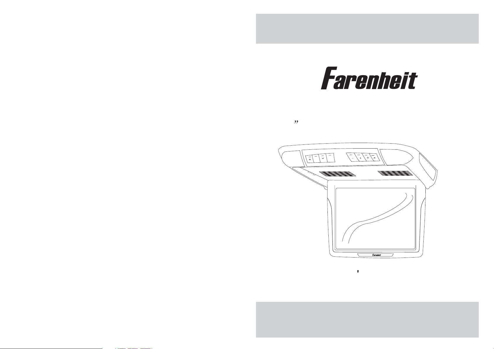
T-1200CM
12.1 Universal Ceiling Mount Monitor
M
E
MENU
AV
EXIT
OWNER S MANUAL
POWER
Page 2

Page 3
CONTENTS
Please read this User,s Manual in detail and use the set properly.
CAUTION 3
INSTALLATION 5
NAME AND FUNCTION OF EACH PART 6
Unit 6
Remote Control 7
PICTURE CONTROL 8
CONNECTIONS 9
HOW TO OPERATION THE MONITOR 10
Releasing The Monitor 10
How To Watch Monitor 10
SPECIFICATIONS 11
2
Page 4

CAUTION
Please read and observe all warnings and instructions in this owner s manual
,
and those marked on the unit. Retain this booklet for future reference.
There are two kinds of alarm symbols as follows:
The lightening flash with arrowhead symbol within an equilateral
WARNING
triangle is intended to alert the user to the presence of
dangerous voltage within the product s enclosure that may be
of sufficient magnitude to constitute a risk of electric shock to
people.
,
The exclamation point within an equilateral triangle is intended
to alert the user to the presence of important operating and
maintenance (servicing) instructions in the literature accompanying
CAUTION
the product.
WARNING
Installation of all TV monitors
P
O
W
E
R
A
V
MEN
U
must be out of the driver s
field of sight.
Do not mount the product where
it will obstruct the deployment of
the airbag or in an area where it
would affect the vehicular control.
Also be careful to avoid mounting
the product where it can become
hazardous during sudden stops or
in the event of an accident.
Do not try and service these
products yourself, Seek only
a qualified service center or
factory service center.
Be careful not to drop or
apply under pressure to the
front panel of your video
monitor. If the screen cracks
due to misuse, your warranty
will be void!
Use extra caution with any liquids
in your car. If you or your child
Spills any liquid on these products,
pull your vehicle to the roadside
or wipe the products with a towel. Do not
operate the equipment until all liquids have
either evaporated or you have had the monitor
inspected at a service center by a qualified
technician, Severe harm or danger can
Occur.
and turn the key off to disconnect
Use only a damp cloth to clean
the screen and use only purified
water on the cloth. Wring out all
excess water prior to wiping the
screen. Do not use any cleaners
or chemicals to clean the screen.
In most cases a dry cloth will do!
3
Page 5

SPECIFICATIONS
CAUTION
CAUTION
Power Requirements
Power Consumption
Screen Size
Screen Format
Resolution Pixel
A/V Inputs
Dimensions(
Dimensions(Without shroud)
IR Power Requirements
IR Power Consumption
IR Transmitter Frequency
LCD Panel Type
Compatible video standard
Note : This equipment has been tested and found to comply with the limits for
a Class A digital device, pursuant to part 15 of the FCC Rules. These limits
are designed to provide reasonable protection against harmful interference
when the equipment is operated in a commercial environment.
This equipment generates, uses, and can radiate radio frequency energy and,
if not installed and used in accordance with the instruction manual, may cause
harmful interference to radio communications. Operation of this equipment in
a residential area is likely to cause harmful interference in which case the user
will be required to correct the interference at his own expense.
With shroud)
DC 12V
9W
12.1 TFT-LCD
4:3
2400x600
2 A/V RCA Inputs
15.1(L)X13.9(W)X3.5(H)inches
14.8(L)X13.6(W)X2.5(H)inches
DC 12V
3W
Right 2.8MHz Left 2.3MHz
Active Matrix TFT
NTSC/PALAuto Select
Quality installations are best
performed by qualified and
certifled installers.
Don t touch the unit if there is
a flash of lightning. It may
receive an electric shock.
Do not cover heater ducts or vents.
This may cause a fire or an electric
shock.
Watching the monitor for an
extended period of time
with the engine turned off
may deplete the vehicle s
battery.
This product is designed for
operation with a 12 Volt DC,
negative ground vehicle. It
is not suitable for operation
under other conditions or
voltages.
Check Point
1. The operating temperature of this product is limited to 14 F~140 F
(-10 C~60 C).
Your vehicle can reach temperatures up to 100 C in the summertime.
2. When your vehicle is extremely hot or cold you must allow time for your air
conditioner or heater to cool or heat the vehicle and for operating temperatures
to return to normal operating ranges. Your monitor will return to its normal
functions when these operating ranges are achieved.
3. Optimum picture quality is achieved when you are directly in front of the monitor
(+/-45 degrees).
4. If the buttons get stuck, please try to press the up of buttons, it will get back.
It won't impact using normal.
5. If you cann't find the files name in list when playing, please reset units or turn
off/on over again.
6. If the unit cann't be change mode when playing some special files which the
unit didn't support, please reset units or turn off/on over again.
11
4
Page 6

INSTALLATION
HOW TO OPERATE THE MONITOR
1. Open the package and check that these items are presents.
INSTALLATION PLATE
2. Connect the external compoments to the RCAcable or AV output.
(Refer to the connection diagram on page 9)
3.Match the position of installation bracket and
UNIT
installation plate with screwA.
SCREW A SCREW B
Releasing the Monitor
Push the open button (located on the front edge of the screen housing)
and lower the monitor to the desired angle. You can also adjust the
swivel angle.
Make this arrow in DOWN
direction only.
PULL BUTTON
How to watch the monitor
4. Tighten the unit with the supplied
screw B.
1. Connect the monitor to the external devices.
2. Press the POWER button on either the remote control or the unit once to turn
the power on.
Press the same POWER button to turn the power off.
POWER
POWER
UNIT
3. Turn on the external devices and view.
5
REMOTE CONTROLLER
10
Page 7

CONNECTIONS
NAME AND FUNCTION OF EACH PART
Unit
+ 12 V DC Battery
Chassis Ground
ACC
DVD/VCD/CD/CD-R/CD-RW/MP3
PLAY/PAUSE PREV NEXT STOP DVD REMOTE AV EJECT POWER A/VINPUT
YELLOW
BLACK
RED
Reset
Red AUDIO(R)
White AUDIO(L)
Yellow VIDEO
Door Trigger
WHITE
AV Input
(AV 2)
Red AUDIO(R)
White AUDIO(L)
Yellow VIDEO
AV Input
(AV 1)
DVD/VCD/CD/CD-R/CD-RW/MP3
PLAY/PAUSE PREV NEXT STOP DVD REMOTE AV EJECT POWER A/VINPUT
Dome light
Reset
M
E
MENU
AV
EXIT
POWER
Infrared Transmitter
Monitor
(Front)
AUDIO VIDEO
RL
AV2INPUTS
+ DoorTrigger -
Monitor
RESET
(Rear)
9
6
Page 8

NAME AND FUNCTION OF EACH PART
PICTURE CONTROL
OSD MENU EXIT Button
E
EXIT
Dome Light Button
MENU Button
M
MENU
AV
AV Select Button
POWER Button
POWER
Dome Light Button
+/- Buttons
Interface Switch Function
Power Power ON/OFF
AV Signal Select
Menu Press this button for OSD menu.
And select menu option
+
Increase current option value.
Decrease current option value.
-
Contrast/Brightness/Color
To adjust CONTRAST, BRIGHTNESS, COLOR press the MENU button until you
arrive at the screen for that item. Use the arrow buttons to adjust the value. Press
the MENU button to make another adjustment or leave the MENU system.
1. Bring up the on-screen function menu by pressing the MENU button on the unit
or the remote control.
2. Press the MENU button on the unit or the remote control of monitor until you see
the item you wish to adjust.
3. Use the arrow buttons to adjust the value.
4. Press the MENU button to make another adjustment or leave the MENU system.
CONTRAST
50
BRIGHTNESS
50
COLOR
50
POWER KEY
-KEY
LCD MONITOR
REMOTE CONTROL UNIT
7
AV1 /AV2 K EY
MENU KEY
+KEY
8
 Loading...