

Page 1
Starlet /8
®
Power Collision
Link / Activity
12345678
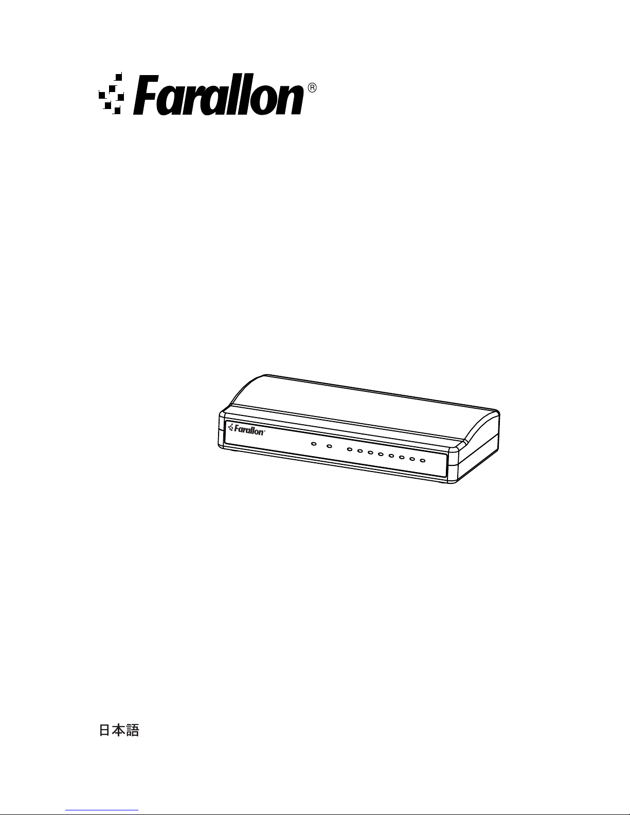
Starlet Ethernet Hub
User’s Guide
Thank you for purchasing a Farallon Starlet Ethernet Hub. This
hub brings unmatched flexibility to Local Area Network (LAN)
environments, providing your network with multiple wiring
connections for up to 4, 5 or 8 Unshielded Twisted Pair (UTP)
ports. The hub can
be used to
network Ethernet
workstations, or
to connect
additional hubs using standard
10Base-T cables. Compact, light and robust, the
Starlet Ethernet Hub provides the ideal solution for your small,
medium or large 10Base-T LAN environment.
Deutsch ............................................................................... 7
Español ............................................................................... 9
Français .............................................................................. 11
Italiano ............................................................................... 13
.................................................................................. 15
Page 2

2
Features
Your Starlet Ethernet Hub offers the following features:
• Full compliance with IEEE 802.3 Ethernet standards
• 4, 5 or 8 RJ-45 10Base-T ports
• Uplink switch for connecting secondary hubs
• Automatic partitioning of faulty ports
• Power LED, Collision LED and Link/Activity LEDs
• External power supply
• CE and FCC Class A certification
Getting Started
You should find the items you need to install your Starlet
Ethernet Hub inside the package:
• 4, 5 or 8 port Starlet Ethernet Hub
• User Manual
• Power Adapter*
*supplied separately outside of North America
Copyright
Copyright © 1999 Farallon Communications, Inc. v.1298.
All rights reserved.
This manual and any associated artwork, software and product designs
are copyrighted with all rights reserved. Under the copyright laws such
materials may not be copied, in whole or part, without the prior written
consent of Farallon. Under the law, copying includes translation to
another language or format.
Farallon Communications, Inc.
3089 Teagarden St.
San Leandro, CA 94577-5720 U.S.A.
Part Number: For additional copies of this manual, order Farallon part
number 6120349-00-01.
Page 3
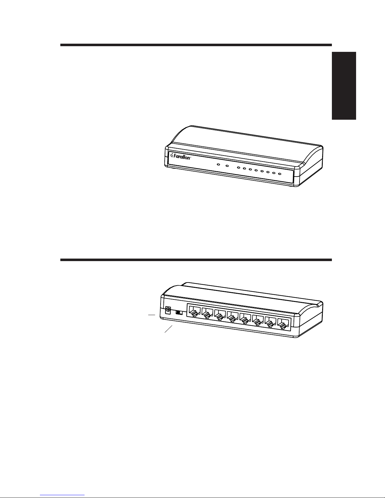
Front Panel
1
4
3
2
7.5VDC 700mA
Normal Uplink
5
6
7
8
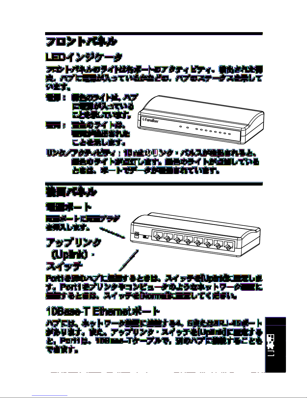
LED Indicators
The lights on the front panel indicate the status of the hub,
including activity for each port, any detected collisions, and
whether the hub is receiving power.
Power: A green light
indicates that
the hub is
3
English
receiving
power.
Starlet /8
®
Power Collision Link / Activity
12345678
Collision: An amber light
indicates that a collision
has been detected.
Link/Activity: A stable green light indicates that a 10mb link
pulse has been detected. A blinking green light
indicates data transmission activity on the port.
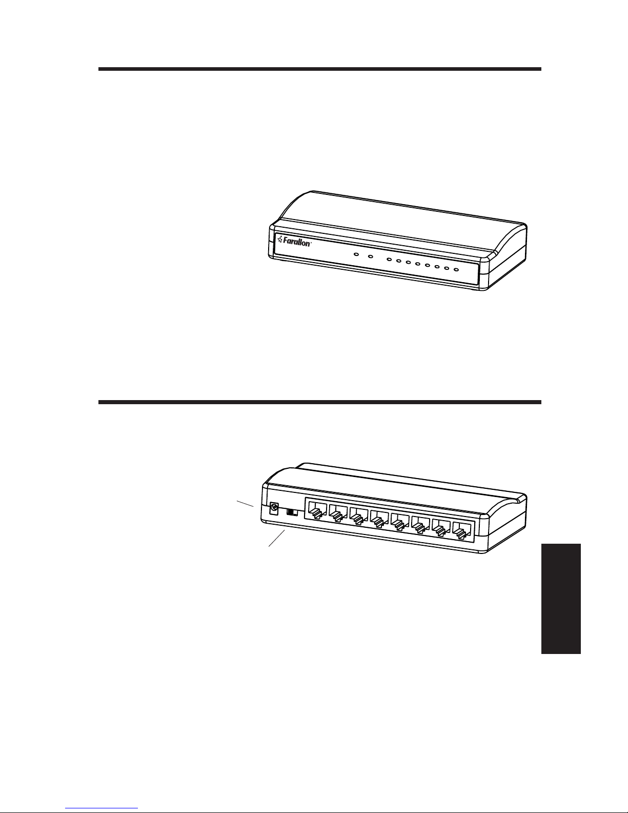
Rear Panel
Power Port
Insert the power plug
into the power port.
Uplink Switch
Set the switch to Uplink when connecting Port 1 to another
hub. Set the switch to Normal when connecting Port 1 to a
network device such as a printer or computer.
10Base-T Ethernet Ports
Your hub has 4, 5 or 8 RJ-45 ports to connect to network
devices. Port 1 can also be connected to another hub with a
10Base-T cable when the uplink switch is set to Uplink.
Page 4
4
Installing the Ethernet Hub
Caution: Using an AC power adapter with incorrect voltage or
polarity may damage your Starlet Ethernet Hub. Make sure you
are using the correct power adapter before you connect the hub.
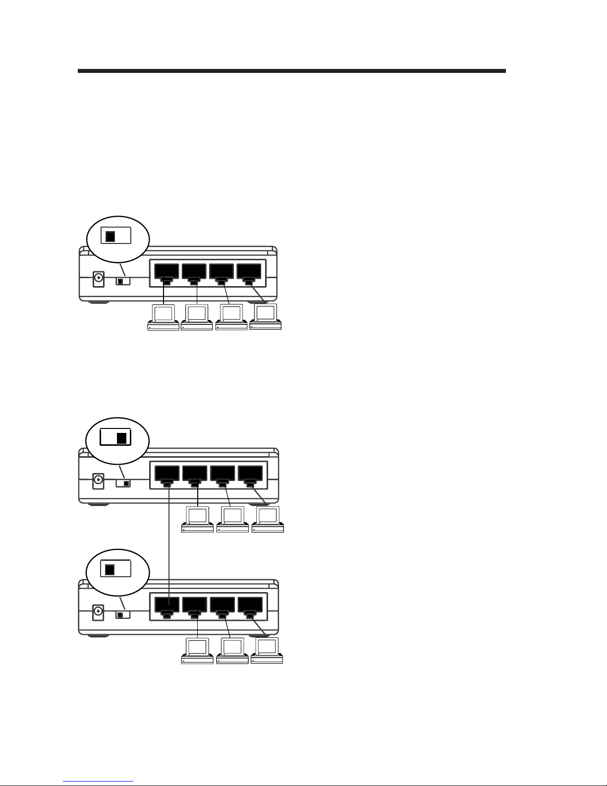
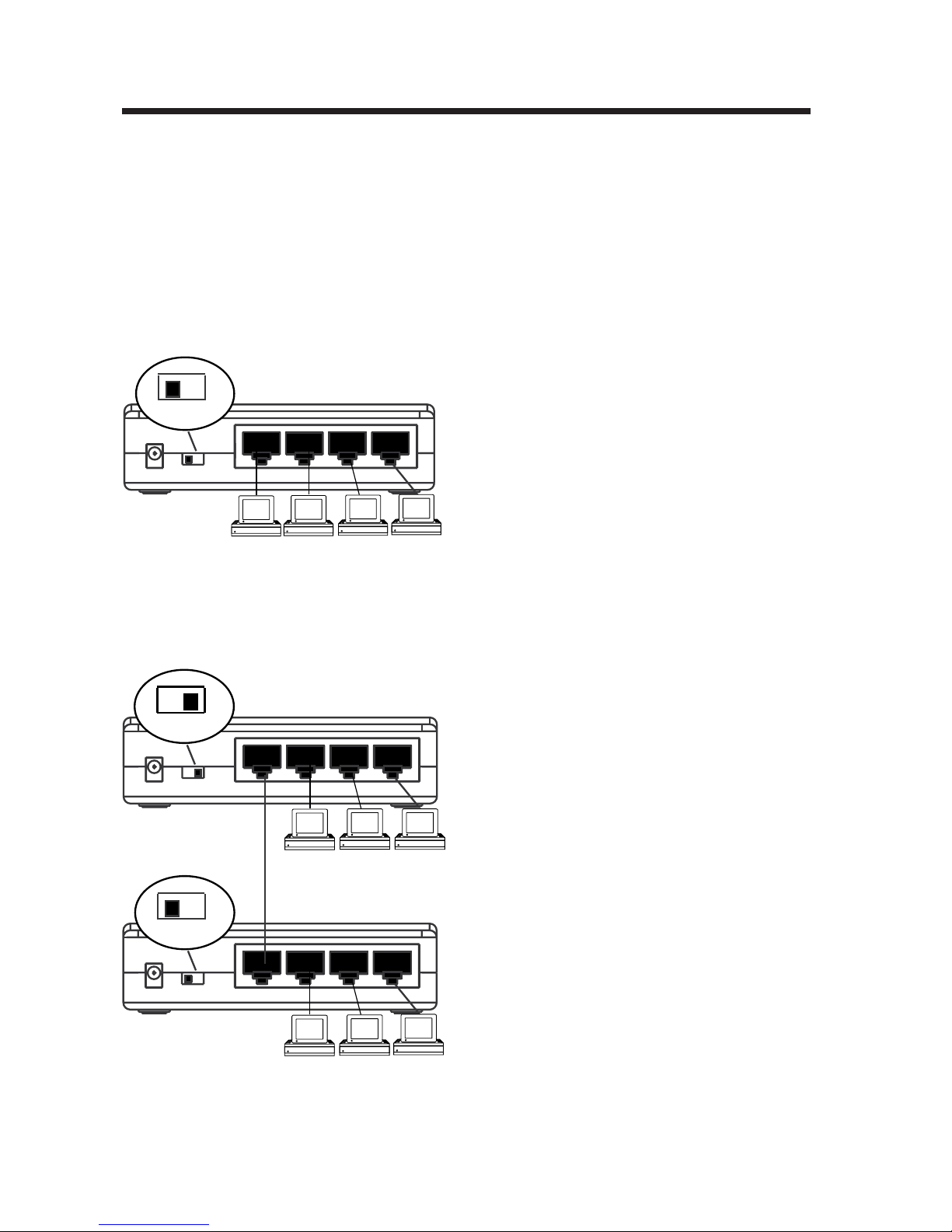
10Base-T Network Device to Hub Connection
To connect 10Base-T Ethernet network devices to your hub:
• Make sure the Port 1 uplink
switch is set to Normal.
Normal
• Use standard 10Base-T cables
7.5VDC 500mA Normal Uplink
2
1
4
3
(category 3 or 5) to connect
the Ethernet port of each
network device to a port on the
hub.
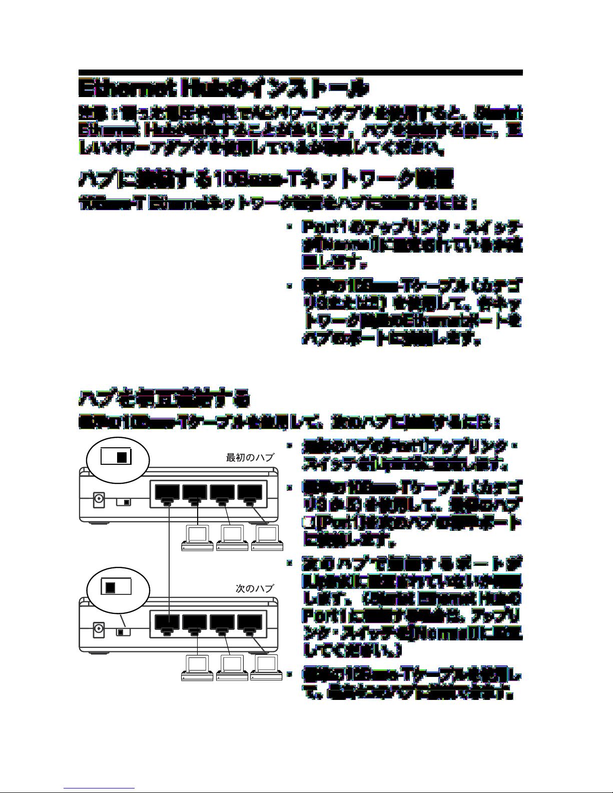
Interconnecting Hubs
To connect a second hub using a standard 10Base-T cable:
• Set the Port 1 uplink switch on
the primary hub to Uplink.
Uplink
7.5VDC 500mA Normal Uplink
Normal
PRIMARY HUB
2
1
SECONDARY HUB
4
3
• Use a standard 10Base-T
cable (category 3 or 5) to
connect Port 1 on the primary
hub to any normal port on the
secondary hub.
• Make sure that the port you
connect to on the secondary
hub is not set to Uplink. (If you
connect to Port 1 on a Starlet
2
7.5VDC 500mA Normal Uplink
1
Ethernet Hub, set the uplink
4
3
switch to Normal.)
• You can connect up to four
hubs using standard 10Base-T
cables.
Page 5

Specifications
• Standards: IEEE 802.3 10Base-T
• Interface: RJ-45 connectors
• Cable: Type: 10Base-T (UTP)
Length: 100 meters maximum
• Indicators/LEDs: Power, Collision, Port Link/Activity
• Dimensions: 4 Port: 100.5mm x 78mm x 27mm
4" x 3" x 1"
5/8 Port: 153mm x 78mm x 27mm
6" x 3" x 1"
• Temperature: Operating: 0 to +40%C
Storage: -20%C to +70%C
• Humidity: Operating: 10% to 90% RH
5
• Voltage: 4 Port: 7.5Vdc@500mA
5/8 Port: 7.5Vdc@700mA
• Frequency: 47Hz to 63Hz
• MTBF (calculated): 4 Port: 303,712 hours
5 Port: 230,142 hours
8 Port: 222,612 hours
Farallon Technical Support
Farallon is committed to providing its customers with reliable products
and excellent technical support. If you have any questions, concerns, or
suggestions, please contact Farallon Customer Service at:
(510) 346-8001 phone
(510) 346-8119 fax
Internet: [email protected]
Farallon Customer Service
3089 Teagarden St.
San Leandro, California 94577-5720 USA
If you are not located in the United States or Canada, you can get service
locally by contacting your nearest Farallon reseller or distributor or
Farallon directly. Please go to www.farallon.com for Farallon product
information on the Internet.
Page 6

6
Limited Warranty and Limitation of Remedies
Farallon warrants to you, the end user, that the accompanying Farallon product, which
may include third party products or technology (the “Product”) will be free from defects
in materials and workmanship under normal use. This is a lifetime warranty. Farallon’s
entire liability and your sole remedy under this warranty during the warranty period is
that Farallon shall, at its option, either repair the Product or refund the original
purchase price of the Product. In order to make a claim under this warranty you must
comply with the following procedure:
1. Contact Farallon Customer Service within the warranty period to obtain a Return
Materials Authorization (“RMA”) number.
2. Return the defective Product and proof of purchase, shipping prepaid, to Farallon
with the RMA number prominently displayed on the outside of the package. If you are
located outside of the United States or Canada, please contact your dealer in order to
arrange for warranty service.
THE ABOVE WARRANTIES ARE MADE BY FARALLON ALONE, AND THEY ARE THE ONLY
WARRANTIES MADE BY ANYONE REGARDING THE ENCLOSED PRODUCT. Farallon and
its licensor(s) make no other warranties, express or implied, including without limitation
the implied warranties of merchantability and fitness for a particular purpose, regarding
the enclosed product. Except as otherwise expressly provided above, Farallon and its
licensor(s) do not warrant, guarantee or make any representation regarding the use or
the results of the use of the product in terms of its correctness, accuracy, reliability,
currentness, or otherwise. The entire risk as to the results and performance of the
product is assumed by you. The exclusion of implied warranties is not permitted by
some states or jurisdictions, so the above exclusion may not apply to you. IN THAT
CASE, ANY IMPLIED WARRANTIES ARE LIMITED IN DURATION TO NINETY (90) DAYS
FROM THE DATE OF DELIVERY OF THE PRODUCT. There may be other rights that you
may have which vary from jurisdiction to jurisdiction.
Regardless of whether or not any remedy set forth herein fails of its essential purpose,
in no event will Farallon, its licensor(s) and the directors, officers, employees or agents
of any of them be liable to you for any consequential, incidental or indirect damages
(including damages for loss of business profits, business interruption, loss of business
information, and the like) arising out the use or inability to use the product even if
Farallon or its licensor(s) have been advised of the possibility of such damages.
Because some states or jurisdictions do not allow the exclusion or limitation of liability
for consequential or incidental damages, the above limitations may not apply to you.
Farallon and its licensor(s) liability to you for actual damages from any cause
whatsoever, and regardless of the form of the action (whether in contract, tort
[including negligence], product liability or otherwise), will be limited to $50.
Page 7
7
1
4
3
2
7.5VDC 700mA
Normal Uplink
5
6
7
8
Vorderseite
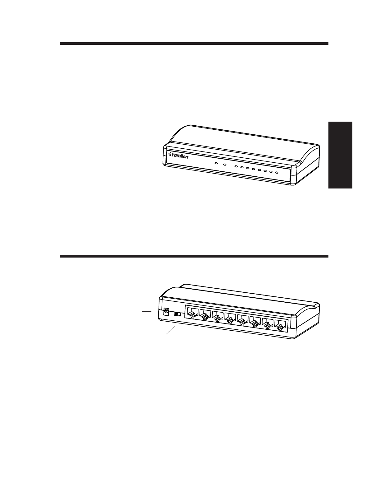
LED-Anzeigen
An den Leuchtanbzeigen auf der Vorderseite ist der Status des
Hubs zu erkennen, hierzu gehören die Aktivität der einzelnen
Anschlüsse, alle ermittelten Kollisionen und ob der Hub mit
Strom versorgt wird.
Netz: Die grüne LED
zeigt an, daß
der Hub
mit Strom
Starlet /8
®
Power Collision Link / Activity
12345678
versorgt wird.
Kollision: Die bernsteinfarbene LED zeigt an,
daß eine Kollision ermittelt wurde.
Link/Aktivität: Die durchgehend grüne LED zeigt an, daß eine
10mb-Link-Impulsfrequenz ermittelt wurde. Die
Datenübertragungsaktivität am Anschluß wird durch
eine blinkende grüne LED ausgewiesen.
Rückseite
Netzanschluß
Stecken Sie das
Netzkabel in die
Netzanschlußbuchse.
Deutsch
Uplink-Schalter
Stellen Sie den Schalter auf „Uplink”, wennder Anschluß 1 mit
einem anderen Hub verbunden werden soll. Stellen Sie den Schalter
auf „Normal”, wenn der Anschluß 1 mit einem Netzwerkgerät , z.B.
einem Drucker oder Computer verbunden werden soll.
10Base-T-Ethernet-Anschlüsse
Der Hub verfügt über 4, 5 oder 8 RJ-45-Anschlüsse zum
Anschluß von Netzwerkgeräten. Zudem kann der Anschluß 1
über ein 10Base-T-Kabel mit einem anderen Hub verbunden
werden, sofern der Uplink-Schalter auf „Uplink” gestellt wurde.
Page 8
8
Installieren des Ethernet-Hubs
Vorsicht: Der Einsatz eines Wechselstromadapters mit falscher
Spannung oder Polarität kann zu einer Beschädigung des Starlet
Ethernet-Hubs führen. Vergewissern Sie sich, daß Sie den richtigen
Netzadapter verwenden, bevor Sie den Hub anschließen.
Verbindung zwischen 10Base-T-Netzwerkgerät und Hub
So schließen Sie 10BaseT-Ethernet-Netzwerkgeräte an den
Hub an:
• Vergewissern Sie sich, daß der
Uplink-Schalter von Anschluß 1
Normal
auf „Normal” eingestellt wurde.
• Verbinden Sie den Ethernet-
7.5VDC 500mA Normal Uplink
2
1
4
3
Anschluß eines jeden
Netzwerkgeräts über ein Standard10Base-T-Kabel (Kategorie 3 oder
5) mit einem Anschluß am Hub.
Hintereinanderschalten von Hubs
So schließen Sie einen zweiten Hub über ein Standard-10Base-TKabel an:
• Stellen Sie den Uplink-Schalter von
Anschluß 1 am primären Hub auf
„Uplink”.
• Verbinden Sie Anschluß 1 am
primären Hub über ein Standard10Base-T-Kabel (Kategorie 3 oder
5) mit einem beliebigen normalen
Uplink
7.5VDC 500mA Normal Uplink
PRIMÄRER HUB
2
1
4
3
SEKUNDÄRER HUB
Normal
2
7.5VDC 500mA Normal Uplink
1
Anschluß am sekundären Hub.
• Vergewissern Sie sich, daß
der Anschluß am sekundären Hub,
mit dem Sie eine Verbindung
4
3
herstellen, auf „Uplink” gestellt ist.
• Über Standard-10Base-T-Kabel
können Sie bis zu vier Hubs
miteinander verbinden.
Page 9
Panel delantero
1
4
3
2
7.5VDC 700mA
Normal Uplink
5
6
7
8
Indicadores LED
Las luces en el panel delantero indican el estado del
concentrador de enlaces, incluyendo la actividad de cada
puerto, las colisiones detectadas, y si el concentrador de
enlaces está recibiendo energía.
Energía: una luz verde
indica que el
9
concentrador
de enlaces
Starlet /8
®
Power Collision Link / Activity
12345678
está recibiendo energía.
Colisión: una luz ámbar indica que se ha
detectado una colisión.
Enlace/actividad: una luz verde fija indica que se ha detectado
un impulso de enlace de 10 mb. Una luz verde intermitente
indica actividad de transmisión de datos en el puerto.
Panel trasero
Puerto de alimentación eléctrica
Inserte el enchufe de
alimentación eléctrica
en este puerto.
Conmutador de
Español
Español
enlace ascendente
Ponga el conmutador en la posición
al conectar el puerto 1 a otro concentrador de enlaces, y en la
posición
Normal
al conectar dicho puerto a un dispositivo de
red tal como un ordenador o una impresora.
Puertos 10Base-T Ethernet
Su concentrador de enlaces tiene 4, 5 u 8 puertos RJ-45 para
su conexión con dispositivos de red. El puerto 1 también puede
conectarse a otro concentrador de enlaces mediante un cable
10Base-T cuando el conmutador de enlace ascendente está en
la posición
Uplink
Uplink
(enlace ascendente)
.
Page 10
10
Instalación del concentrador de enlaces Ethernet
Precaución: el uso de un adaptador de corriente alterna con un voltaje
o una polaridad incorrecta puede dañar su concentrador de enlaces
Ethernet Starlet. Asegúrese de utilizar el adaptador de corriente
correcto antes de conectar el concentrador de enlaces.
Conexión de un dispositivo de red 10Base-T al
concentrador de enlaces
Para conectar dispositivos de red 10Base-T Ethernet a su concentrador
de enlaces:
• Asegúrese de que el conmutador
de enlace ascendente del puerto
Normal
1 esté en la posición
Normal
.
• Utilice cables 10Base-T estándar
7.5VDC 500mA Normal Uplink
2
1
4
3
(categoría 3 ó 5) para conectar el
puerto Ethernet de cada
dispositivo de red a un puerto
en el concentrador de enlaces.
Interconexión de concentradores de enlaces
Para conectar un segundo concentrador de enlaces mediante un cable
10Base-T estándar:
• Ponga el conmutador de enlace
ascendente del puerto 1 del
concentrador de enlaces primario en la
posición
Uplink
.
• Utilice un cable 10Base-T estándar
(categoría 3 ó 5) para conectar el
puerto 1 del concentrador de enlaces
primario a cualquier puerto normal del
concentrador de enlaces secundario.
• Asegúrese de que el puerto al que
conecta en el concentrador de enlaces
secundario no esté en la posición
Uplink
Uplink
7.5VDC 500mA Normal Uplink
Normal
7.5VDC 500mA Normal Uplink
CONCENTRADOR DE
ENLACES PRIMARIO
2
1
CONCENTRADOR DE
ENLACES SECUNDARIO
2
1
4
3
4
3
.
• Puede conectar hasta 4
concentradores de enlaces mediante
cables 10Base-T estándar.
Page 11
11
1
4
3
2
7.5VDC 700mA
Normal Uplink
5
6
7
8
Panneau avant
Indicateurs à diodes
Les voyants du panneau avant indiquent l’état de connexions
du hub, c'est à dire l’activité de chaque port, toute collision
détectée et si l’appareil est sous tension.
Alimentation: un voyant
vert indique
que l’appareil
Starlet /8
est sous
tension
Collisions: un voyant ambré indique
qu’une collision a été détectée.
®
Power Collision Link / Activity
12345678
Liaison/Activité: un voyant vert indique qu’une impulsion de
liaison à 10 Mo a été détectée. Un voyant vert
clignotant indique que la transmission de données
est en cours sur le port.
Panneau arrière
Connecteur d’alimentation
Insérez la prise
d’alimentation dans le
connecteur
d’alimentation.
Commutateur Uplink
Placez le commutateur sur
connexion du port 1 vers un autre hub. Placez le commutateur
sur
Normal
lors de la connexion du port 1 à un périphérique de
Uplink
(liaison amont) lors d’une
Français
réseau tel qu’une imprimante ou un ordinateur.
Ports 10Base-T Ethernet
Votre hub dispose de 4, 5 ou 8 ports RJ-45 pour connexions à
des périphériques. Le port 1 peut également être connecté à un
autre hub au moyen d’un câble 10Base-T standard lorsque le
commutateur de liaison est placé sur
Uplink
.
Page 12
12
Installation du hub Ethernet
Attention: l’utilisation d’un adaptateur secteur avec une tension
ou une polarité incorrecte peut endommager votre hub Ethernet
Starlet. Veillez à utiliser le bon adaptateur secteur avant de
brancher le hub.
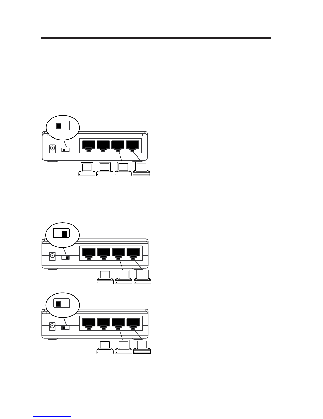
Connexion d’un périphérique 10Base-T au hub
Pour brancher un périphérique de réseau de type 10Base-T à votre hub:
• Assurez-vous que le
Normal
commutateur de liaison amont
est placé sur
Normal
.
7.5VDC 500mA Normal Uplink
2
1
4
3
10Base-T (classe 3 ou 5) pour
connecter le port Ethernet de
chaque périphérique à un port
du hub.
Liaison entre deux hubs
Pour connecter un second hub au moyen d’un câble 10Base-T:
• Placez le commutateur de liaison
• Utilisez des câbles standard
amont du port 1 du hub primaire
sur
Uplink
.
• Utilisez un câble standard
10Base-T (classe 3 ou 5) pour
connecter le port 1 du hub
primaire au hub secondaire.
• Veillez à ce que le port auquel
vous vous connectez sur le hub
secondaire n’est pas commuté
sur
Uplink
. (Si vous connectez le
port 1 sur un autre hub Ethernet
Starlet, placez le connecteur de
liaison amont sur
Normal
).
Uplink
7.5VDC 500mA Normal Uplink
Normal
7.5VDC 500mA Normal Uplink
HUB PRIMAIRE
2
1
HUB SECONDAIRE
2
1
4
3
4
3
• Vous pouvez connecter jusqu'à
quatre hubs en utilisant des
câbles standard 10Base-T.
Page 13
13
1
4
3
2
7.5VDC 700mA
Normal Uplink
5
6
7
8
Pannello frontale
Indicatori LED
Le luci sul pannelo frontale indicano lo stato dell’hub
includendo l’attivitá di ogni porta, eventuali collisioni rilevate e
se l’hub é collegato o meno.
Energia: Una luce di
colore verde
indica che
Starlet /8
l’hub é
®
Power Collision Link / Activity
12345678
collegato.
Collisione: Una luce di colore ambra
indica che é stata rilevata una collisione.
Attivitá/collegamento: Una luce fissa di colore verde indica che
é stato rilevato un collegamento a impulsi di 10mb.
Una luce alternata di colore verde indica l’attivitá di
trasmissione dei dati della porta.
Pannello posteriore
Porta di alimentazione
Inserire il cavo di
alimentazione
nell’apposita porta.
Interruttore Uplink
Impostare l’interruttore su
connessione della porta 1 ad un altro hub. Impostare
l’interruttore su
Normal
ad un dispositivo di rete quali una stampante o un computer.
Porte Ethernet 10Base-T
L’hub ha le porte RJ-45 4, 5 o 8 per connettersi a dispositivi di
rete. La porta 1 puó anche essere connessa ad un altro hub
con un cavo 10Base-T quando l’interruttore é impostato su
Uplink
.
Uplink
durante la
durante la connessione della porta 1
Italiano
Page 14
14
Installazione dell’hub Ethernet
Attenzione: L’uso di un adattatore da rete (AC) con voltaggio o
polaritá errati potrebbe danneggiare l’hub Ethernet Starlet.
Assicurarsi di usare l’adattatore corretto prima di connettersi all’hub.
Connessione del dispositivo di rete 10Base-T all’hub
Per connettere il dispositivo di rete 10Base-T all’hub:
• Assicurarsi che l’interruttore
della porta 1 sia impostato su
Normal
Normal
.
7.5VDC 500mA Normal Uplink
2
1
4
3
• Usare dei cavi 10Base-T
standard (categorie 3 o 5) per
connettere la porta Ethernet di
ogni dispositivo di rete alla
porta dell’hub.
Interconnessione di hub
Per connettere un secondo hub usando un cavo 10Base-T standard:
• Impostare l’interruttore della
Uplink
7.5VDC 500mA Normal Uplink
HUB PRIMARIO
2
1
4
3
porta 1 dell’hub primario su
Uplink
.
• Usare un cavo 10Base-T
standard (categoria 3 o 5) per
connettere la porta 1 dell’hub
primario ad una qualsiasi porta
normale dell’hub secondario.
HUB SECONDARIO
Normal
2
7.5VDC 500mA Normal Uplink
1
• Assicurarsi che la porta dell’hub
secondario a cui ci si connette
non sia impostata su
4
3
ci si connette alla porta 1 dell’hub
Uplink
. (Se
Ethernet Starlet, impostare
l’interruttore su
Normal
).
• È possibile connettersi con fino
a quattro hub usando cavi
10Base-T standard.
Page 15
Starlet /8
1
4
3
2
7.5VDC 700mA
Normal Uplink
5
6
7
8
®
Power Collision Link / Activity
12345678
15
Page 16
16
Normal
7.5VDC 500mA Normal Uplink
Uplink
7.5VDC 500mA Normal Uplink
2
1
2
1
4
3
4
3
Normal
2
7.5VDC 500mA Normal Uplink
1
4
3
 Loading...