

Page 1

MPC-1500 PlusPlus
Fire Alarm System Control Unit
Owner’s Manual
12530-120 / 12530-240
12540-120 / 12540-240
P/N 447203
Issue I
7/2001
Faraday, LLC / 805 South Maumee Street / Tecumseh, Michigan 49286
Phone 517-423-2111 Fax 517-423-2320
Copyright © 2001 Faraday, LLC, All Rights Reserved
Page 2

12530/12540 OWNER'S MANUAL
Table of Contents
I. INTRODUCTION ..................................................................................................................I-1
CONTROL UNIT LIMITATIONS............................................................................................. I-1
INSTALLATION AND WARRANTY INFORMATION................................................................ I-2
Installer Information:.........................................................................................................I-2
Original Purchaser Information:.........................................................................................I-2
PREFACE ............................................................................................................................ I-3
II. DESCRIPTIONS..................................................................................................................II-1
SYSTEM DESCRIPTION.....................................................................................................II-1
HARDWARE CONFIGURATION ..........................................................................................II-1
MINIMUM CONTROL UNIT CONFIGURATION.....................................................................II-2
Power Supply .................................................................................................................II-2
Addressable Device Circuits ............................................................................................II-2
Notification Appliance Circuits ..........................................................................................II-2
RS485 Communications Circuit........................................................................................II-2
Status Relays .................................................................................................................II-2
City Tie Connection.........................................................................................................II-2
RS232 Printer Connection ...............................................................................................II-2
OPTIONAL CONTROL UNIT CONFIGURATION ...................................................................II-3
Initiating Device Circuits ..................................................................................................II-3
Addressable Device Circuits ............................................................................................II-3
Notification Appliance Circuits ..........................................................................................II-3
Isolated Printer Connection ..............................................................................................II-3
User Programmable Relays .............................................................................................II-3
Digital Alarm Communicator ............................................................................................II-3
Digital Alarm Communicator ............................................................................................II-3
BATTERY SETS..................................................................................................................II-4
AUXILIARY MODULES ........................................................................................................II-4
Remote LCD Annunciator................................................................................................II-4
Serial Relay Unit and Serial Relay Extender .....................................................................II-4
Serial Annunciator Unit and Serial Annunciator Extender...................................................II-4
Network Interface Board ..................................................................................................II-4
Auxiliary Power Supplies .................................................................................................II-4
ADDRESSABLE DEVICES ..................................................................................................II-5
Faraday Addressable Detectors .......................................................................................II-5
Other Faraday Addressable Devices ................................................................................II-5
System Sensor Addressable/Analog Sensors ...................................................................II-5
Other System Sensor Addressable Devices......................................................................II-6
PROCESSOR CONTROLLED OUTPUT ZONES...................................................................II-6
Output Sounding Patterns ...............................................................................................II-6
Control of Audible Silencing .............................................................................................II-6
Audible Silence Inhibit.....................................................................................................II-6
EVENT HISTORY ................................................................................................................II-7
GENERAL DESIGN FEATURES ..........................................................................................II-8
Environmental.................................................................................................................II-8
Power Limiting ................................................................................................................II-8
Ground Fault Detection ...................................................................................................II-8
Transient Protection ........................................................................................................II-8
Security Functions ..........................................................................................................II-8
REGULATORY STANDARDS ..............................................................................................II-8
Underwriters Laboratories ................................................................................................II-8
GENERAL SPECIFICATIONS ..............................................................................................II-9
P/N 447203 Issue I i
Page 3

12530/12540 OWNER'S MANUAL
Environmental.................................................................................................................II-9
Primary Supply ...............................................................................................................II-9
Secondary and Trouble Power Supply..............................................................................II-9
Auxiliary Power Outputs ..................................................................................................II-9
Addressable Device Circuits ............................................................................................II-9
Notification Appliance Circuits ........................................................................................ II-10
Status Relays ............................................................................................................... II-10
RS485 Communications Circuit...................................................................................... II-10
City Tie .........................................................................................................................II-10
RS232 Printer Output .................................................................................................... II-11
Initiating Device Circuits (Optional board P/N 12503) .......................................................II-11
DACT Expansion Module (Optional module P/N 12513) .................................................. II-11
Alarm Relay Board (Optional board P/N 12402).............................................................. II-11
III. CONTROL UNIT OPERATION............................................................................................III-1
OPERATION INSTRUCTIONS ............................................................................................ III-1
A. Standby Condition .....................................................................................................III-1
B. Alarm Condition ........................................................................................................III-1
C. Trouble Condition .....................................................................................................III-2
D. Supervisory Condition ...............................................................................................III-2
E. Maintenance .............................................................................................................III-2
ADDITIONAL OPERATING PROCEDURES ......................................................................... III-3
A. Lamp Test................................................................................................................III-3
B. Drill..........................................................................................................................III-3
C. Recall ......................................................................................................................III-3
D. Pre-Alarm .................................................................................................................III-3
E. General Alarm ..........................................................................................................III-3
F. Tornado ....................................................................................................................III-3
G. History .....................................................................................................................III-4
12530/12540 OPERATING INSTRUCTIONS........................................................................ III-5
12506 OPERATING INSTRUCTIONS .................................................................................. III-6
IV. CONTROL UNIT INSTALLATION ...................................................................................... IV-1
PARTS SUPPLIED.............................................................................................................IV-1
CAUTIONS ........................................................................................................................IV-1
CONTROL UNIT LOCATION...............................................................................................IV-1
ENCLOSURE MOUNTING..................................................................................................IV-1
A. Surface Mounting Instructions - 12530 ....................................................................... IV-2
B. Surface Mounting Instructions - 12540 ....................................................................... IV-3
C. Semi-Flush Mounting Instructions - 12530 ................................................................. IV-4
D. Semi-Flush Mounting Instructions - 12540 ................................................................. IV-5
E. Knock-Outs ............................................................................................................. IV-6
F. Main Termination Board Installation ........................................................................... IV-6
G. Loop Driver Board Installation ................................................................................... IV-7
H. Transformer Mounting.............................................................................................. IV-8
I. Front Plate Assembly................................................................................................ IV-9
J. Front Plate Mounting ...............................................................................................IV-10
K. Door Assembly.......................................................................................................IV-11
L. AC Supply Connection .............................................................................................IV-11
M. Battery Installation..................................................................................................IV-11
N. Powering the Control Unit ........................................................................................IV-12
O. Checking Supervised Circuits..................................................................................IV-12
P. Optional Modules ....................................................................................................IV-12
Q. System Wiring........................................................................................................IV-12
R. Check System Operation .........................................................................................IV-12
V. SYSTEM WIRING ............................................................................................................... V-1
P/N 447203 Issue I ii
Page 4

12530/12540 OWNER'S MANUAL
CONTROL UNIT WIRING OVERVIEW ................................................................................ V-1
WIRING SEPARATION....................................................................................................... V-2
PRIMARY AND SECONDARY POWER WIRING .................................................................. V-3
PRINTER WIRING .............................................................................................................. V-3
AUXILIARY POWER OUTPUT WIRING............................................................................... V-4
System Power Requirement Calculations ........................................................................ V-4
Auxiliary Power Supply ................................................................................................... V-4
Battery Size Calculations................................................................................................ V-4
CITY TIE AND STATUS RELAYS WIRING .......................................................................... V-5
NAC WIRING..................................................................................................................... V-5
RS485 COMMUNICATIONS CIRCUIT ................................................................................. V-6
Remote Device Power.................................................................................................... V-6
Remote Device Data...................................................................................................... V-6
ADDRESSABLE DEVICE CIRCUIT..................................................................................... V-7
Addressable Device Wiring Diagrams .............................................................................. V-7
Addressable/Analog Sensors .........................................................................................V-11
Addressable Modules....................................................................................................V-17
VI. PROGRAMMING THE CONT ROL UNIT............................................................................. VI-1
MAIN TERMINATION BOARD JUMPERS............................................................................VI-1
MAIN LOGIC BOARD JUMPERS ........................................................................................VI-2
LOOP DRIVER BOARD JUMPERS .....................................................................................VI-2
CONVENTIONAL EXPANSION BOARD JUMPERS .............................................................VI-2
LOOP/SIGNAL EXPANSION JUMPERS ..............................................................................VI-3
REMOTE LCD ANNUNCIATOR JUMPER............................................................................VI-4
REMOTE LCD ANNUNCIATOR SWITCHES........................................................................VI-4
SERIAL RELAY UNIT JUMPERS ........................................................................................VI-4
SERIAL RELAY UNIT SWITCHES .......................................................................................VI-5
SERIAL ANNUNCIATOR UNIT JUMPERS ...........................................................................VI-5
SERIAL ANNUNCIATOR UNIT SWITCHES .........................................................................VI-5
KEYPAD PROGRAMMING.................................................................................................VI-6
PROGRAMMING SECURITY ..............................................................................................VI-6
VII. MAINTENANCE ............................................................................................................... VII-1
GENERAL......................................................................................................................... VII-1
QUICK TEST..................................................................................................................... VII-2
VIII. APPENDIX-A: REFERENCE DATA ................................................................................. VIII-1
WIRE SELECTION GUIDES .............................................................................................VIII-1
Resistance of Solid Copper Wire .................................................................................. VIII-1
Initiating Device Circuit Wire Selection Guide................................................................ VIII-1
Notification Appliance Circuit Wire Selection Guide....................................................... VIII-2
Addressable Device Circuit Wire Selection Guide .......................................................... VIII-2
BATTERY SIZE CALCULATIONS .....................................................................................VIII-3
IX. APPENDIX-B: COMPATIBLE DEVICES ............................................................................ IX-1
DEVICES FOR ADDRESSABLE DEVICE CIRCUITS............................................................IX-1
Faraday Addressable Modules....................................................................................... IX-1
Faraday Addressable Detectors ..................................................................................... IX-1
Faraday Bases ............................................................................................................. IX-1
Faraday Accessories..................................................................................................... IX-1
System Sensor Addressable/Analog Sensors ................................................................. IX-2
System Sensor Bases ................................................................................................... IX-2
System Sensor Addressable/Analog Modules ................................................................. IX-2
System Sensor Accessories .......................................................................................... IX-2
DEVICES FOR INITIATING DEVICE CIRCUITS...................................................................IX -3
Manual Stations ............................................................................................................ IX-3
P/N 447203 Issue I iii
Page 5

12530/12540 OWNER'S MANUAL
Waterflow Switches....................................................................................................... IX-3
Supervisory Switches .................................................................................................... IX-4
Contact Type Heat Detectors ......................................................................................... IX-4
UL Compatible Two-Wire (Circuit Powered) Smoke & Heat Detectors .............................. IX-5
UL Compatible Four -Wire (Separately Powered) Smoke Detectors .................................. IX-6
DEVICES FOR NOTIFICATION APPLIANCE CIRCUITS ......................................................IX -7
Notification Appliances .................................................................................................. IX-7
Accessory Devices.......................................................................................................IX-10
DEVICES FOR AUXILIARY POWER OUTPUTS ................................................................ IX -11
Door Holders ...............................................................................................................IX-11
Relays.........................................................................................................................IX-11
X. APPENDIX-C: TROUBLES HOOTING ................................................................................. X-1
TROUBLESHOOTING INDICATORS ....................................................................................X-1
DEFINITIONS FOR EVENT HISTORY ENTRIES .................................................................. X-1
A. General.................................................................................................................... X-1
B. System Troubles....................................................................................................... X-2
C. System Events ......................................................................................................... X-3
XI. APPENDIX-D: INSTALLA TION INSTRUCTIONS ................................................................ XI-1
12522 Loop Driver Board - 447202................................................................................ XI-3
12503 Conventional Expansion Board - 446992 ............................................................. XI-5
12504 Class A Adapter - 446993................................................................................... XI-7
12505 Loop/Signal Expansion - 446994 ......................................................................... XI-9
12506 Remote LCD Annunciator – 446983...................................................................XI-11
12507/12508 Serial Relay Unit/Serial Relay Extender - 447073 .....................................XI-13
12509/12510 Serial Annunciator Unit/Serial Annunciator Extender - 447074...................XI-15
401403 Fire Alarm Accessory Enclosure - 447138 ........................................................XI-17
12511 Serial Isolation Board - 447065 ..........................................................................XI-19
12513 DACT Expansion Module - 447153....................................................................XI-21
12401A Class A Adapter - 447062 ...............................................................................XI-25
12402 Alarm Relay Board - 446062..............................................................................XI-27
12408 Auxiliary Power Supply – 446066 .......................................................................XI-29
12410 Digital Communicator Cable - 446060 ................................................................XI-35
XII. APPENDIX-E: GLOSSARY .............................................................................................. XII-1
P/N 447203 Issue I iv
Page 6

12530/12540 OWNER'S MANUAL
I. INTRODUCTION
CONTROL UNIT LIMITATIONS
This control unit may not show an alarm condition without compatible initiating devices (smoke detectors,
etc.) and notification devices (horn, lights, etc.) connected to it. Electrical ratings of the initiation and
notification appliances must be compatible with the electrical ratings of the control unit and must be
properly interconnected. The wiring used for interconnection must be large enough to carry the total
current for all appliances without excessive voltage drop.
The control unit must be connected to a dedicated primary electrical source that has a high degree of
reliability and adequate capacity for this control unit. The only means of disconnecting this power source
shall be available only to authorized personnel and clearly marked "Fire Alarm Circuit Control".
The control unit must also have connected to it a battery set (24v) that has enough capacity to properly
operate the system for 24 or 60 (depending on system type) hours standby and 5 minutes alarm per
NFPA 72 (chapter 1). These batteries do lose capacity with age. Batteries must be replaced when they
fail to provide the control unit with the required standby and alarm power or after 4 years, whichever
happens first. These batteries must be checked for performance at least two (2) times a year or more
often if local requirements dictate.
Fire alarm control units cannot last forever. Even though this control unit was made to last for the
expected life of the fire alarm system, any part could fail at any time. Therefore a regular test program
should be followed and documented to make sure that each part of the system is tested as in Chapter 7
of NFPA 72 or more often if dictated by local code requirements. Malfunctioning units must be replaced
or repaired immediately by factory authorized service personnel.
NOTE: This control unit is designed to show an alarm condition when the
initiating devices connected to it detect specific conditions. These conditions
may or may not represent a life-threatening condition. Also, evacuation of a
building or area unnecessarily may subject individuals to an unnecessary
hazard. Therefore, it is most important that the building owner, manager, or
representative promulgate, distribute, and/or post instructions describing
steps to be taken when the fire alarm control unit signals an alarm condition.
These instructions should be developed in cooperation and conformance with
representatives of the local authority having jurisdiction.
As a backup or precautionary measure, it is strongly suggested that one of these steps should be to notify
the local fire department of an abnormal condition even where the DACT option (or similar device) is
included in the system.
P/N 447203 Issue I I-1
Page 7

12530/12540 OWNER'S MANUAL
INSTALLATION AND WARRANTY INFORMATION
Warranty Information: Faraday, LLC (the Manufacturer) provides a limited warranty to the original
purchaser of this product. The original purchaser is the party to whom the manufacturer issued its sales
order, generally the manufacturer's distribution. In order to preserve this warranty, it is important that only
persons who have been properly trained and authorized by the manufacturer service the product.
Other parties involved in the installation of this product may have also provided a warranty, which may be
different from that of the manufacturer. The manufacturer will only be responsible to the original
purchaser and only for the manufacturer's own warranty. For further information regarding the
manufacturers warranty, contact the original purchaser.
OWNER'S MANUAL: The owner's manual does not purport to cover all the details or variations in the
equipment described, nor does it provide for every possible contingency to be met in connection with
installation, operation and maintenance. All specifications subject to change without notice. Should
further information be desired or should particular problems arise which are not covered sufficiently, the
matter should be referred to the installer or original purchaser listed below.
Installer Information:
Company:
Installer:
Phone:
Address:
City:
State:
Zip:
Date installed:
Installer's signature:
Original Purchaser Information:
Company:
Phone:
Address:
City:
State:
Zip:
Purchaser's purchase order number:
Date purchased:
Faraday sales order acknowledgment number:
Original purchaser's signature:
P/N 447203 Issue I I-2
Page 8

12530/12540 OWNER'S MANUAL
PREFACE
Along with the use of this instruction manual, the appropriate following standards and the manufacturer's
instructions for initiating and notification devices should be used to install and maintain a functioning fire
alarm signaling system.
NFPA 70 National Electrical Code
NFPA 72 National Fire Alarm Code
NFPA 101 Life Safety Code
For other standards that may apply contact the authority having jurisdiction.
For NFPA publications, contact:
National Fire Protection Association
Batterymarch Park
Quincy, Massachusetts 02269
P/N 447203 Issue I I-3
Page 9

12530/12540 OWNER'S MANUAL
This page is intentionally blank.
P/N 447203 Issue I I-4
Page 10

12530/12540 OWNER'S MANUAL
II. DESCRIPTIONS
SYSTEM DESCRIPTION
The 12530/12540 is an advanced modular fire alarm control unit. It features addressable/analog
detection, programming, and memory capability. Its base configuration includes two addressable device
circuits, with four conve ntional notification appliance circuits.
The 12530 control unit mounts in a 24" x 14-3/8" back-box with overall cover size of 24-9/16" x 14-3/4".
The 12540 control unit mounts in a 35-11/16" x 14-3/8" back-box with overall cover size of 35-31/32" x
14-3/4". Operating controls and indicators are mounted on the plate with a polycarbonate decal for
identification. An 80-character LCD display provides specific indications for addressable devices while
LEDs indicate general panel status.
Semi-flush mounting kits are available for the enclosure.
HARDWARE CONFIGURATION
The main termination board mounts in the rear of the enclosure. The power supply is physically
contiguous with the main board. The 12530/12540 main termination board provides the interface for
external analog system connections, for the addressable device circuit, four notification appliance circuits,
remote signaling and indicating interfaces, and the electronics of the main system power supply. Optional
boards mount on or plug into the main termination board.
The main logic board mounts on the front plate, allowing it to carry the controls and displays which must
be accessible.
All normal operation is controlled from the front of the control unit via push-button switches. Displays are
provided by an 80-character, alphanumeric, backlit LCD display and by discrete LED indicators for major
control unit functions.
The 80-character LCD display is used to display event data, including alarms and troubles, identification
of zone or device, and presentation of history. The display is controlled by a set of four push-button
switches commanding the control processor. A back light is included in the display to assure visibility in
low light, but to conserve power, it is only activated during a reported event or on operation of a display
control switch.
Individual LEDs on the panel are provided to indicate SYSTEM ALARM, PREALARM, SUPERVISORY,
ALARM SILENCED, SYSTEM TROUBLE and AC POWER ON. Direct push-button controls are provided
for ALARM SILENCE, TROUBLE SILENCE/ACKNOWLEDGE, MENU and SYSTEM RESET. These
switches require concurrent use of the security keyswitch.
P/N 447203 Issue I II-1
Page 11

12530/12540 OWNER'S MANUAL
MINIMUM CONTROL UNIT CONFIGURATION
Power Supply
A 4A, 24V nominal power supply provides all operating power to the control unit for both standby and
alarm conditions. Sufficient battery charging capability is available to charge sealed lead-acid batteries
within code requirements for 60 hour quiescent plus 5 minutes alarm. The cabinet will hold batteries only
up to 10 AH. The back-up battery is 24V, maintained by floating on the power supply. The power supply
is physically contiguous with the main board.
Addressable Device Circuits
The main termination board has an addressable loop driver board supporting two addressable device
circuits, that is programmed for connection to Faraday or System Sensor addressable devices.
Faraday Addressable Devices:
Each addressable device circuit drives up to 60 addressable devices, detectors and/or modules.
System Sensor Addressable Devices:
Each addressable device circuit drives up to 99 addressable sensors and 99 addressable
modules.
Notification Appliance Circuits
The base control unit has four notification appliance circuits (NACs). Each circuit can be selected to give
continuous output or one of eight sounding patterns available in the control unit. There is also a system
coder capable of zone coded operation. All of the NACs are power limited and can be wired for Class B
(Style Y) operation or Class A (Style Z) operation with the Faraday 12504 Class A Adapter.
RS485 Communications Circuit
The control unit has a RS485 Communications Circuit that will drive up to 16 remote LCD annunciators
and 8 Serial Relay Units and Serial Annunciator Units on the RS485 communication line.
Status Relays
Five dry relay contacts are provided. These contacts are dedicated to alarm, trouble, supervisory, AC
failure and processor failure indications. The relay contacts are form C and are rated 2A@30VDC or
0.5A@30VAC, resistive.
City Tie Connection
The city tie connection provides reverse polarity, local energy or shunt operation. The polarity reversal
connections provide an alarm circuit with trouble and/or supervisory output.
RS232 Printer Connection
The RS232 printer connection will allow event data to a serial printer, terminal or computer or data from
and to a Network Interface Board.
P/N 447203 Issue I II-2
Page 12

12530/12540 OWNER'S MANUAL
OPTIONAL CONTROL UNIT CONFIGURATION
A maximum control unit configuration can include all of the minimum configuration items plus additions as
noted below. Details of these accessories are given in Appendix D.
Initiating Device Circuits
The Faraday 12503 Conventional Expansion Board provides four initiating device circuits. The IDCs can
be wired for Class B (Style B) operation or Class A (Style D) operation with the Faraday 12401A Class A
Adapter. Up to two 12503 boards may be used.
Addressable Device Circuits
The Faraday 12522 Loop Driver Board with the Faraday 12505 Loop/Signal Expansion board provides
two additional addressable device circuits. Only one 12505 board may be used.
Faraday Addressable Devices:
Each addressable device circuit drives up to 60 addressable devices, detectors and/or modules.
System Sensor Devices:
Each addressable device circuit drives up to 99 addressable sensors and 99 addressable
modules.
Notification Appliance Circuits
The Faraday 12503 Conventional Expansion Board provides two additional notification appliance circuits
(NACs). Each circuit can be selected to give continuous output or one of eight sounding patterns
available in the control unit. There is also a system coder capable of zone coded operation. All of the
NACs are power limited and can be wired for Class B (Style Y) operation or Class A (Style Z) operation
with the Faraday 12401A Class A Adapter. Up to two 12503 boards may be used.
The Faraday 12505 Loop/Signal Expansion board provides four additional notification appliance circuits
(NACs). Each circuit can be selected to give continuous output or one of eight sounding patterns
available in the control unit. There is also a system coder capable of zone coded operation. All of the
NACs are power limited and can be wired for Class B (Style Y) operation or Class A (Style Z) operation
with the Faraday 12504 Class A Adapter. Only one 12505 board may be used.
Isolated Printer Connection
The Faraday 12511 Serial Isolation Board will convert the RS232 printer connection to an isolated output.
User Programmable Relays
The Faraday 12402 Alarm Relay Board provides 12 dry relay contacts. These relay may be programmed
to activate from a device or zone. The relay contacts are form C and are rated 1A@30VDC or
0.5A@30VAC, resistive.
Digital Alarm Communicator
The Faraday 12410 Digital Communicator Cable may be used with the Faraday 15128 Digital Alarm
Communicator. This will allow control unit status data to be sent to a remote receiving station.
Digital Alarm Communicator
The Faraday 12513 DACT (Digital Alarm Communicator Transmitter) Expansion Module provides
telephone line connections for communication with a DACR (Digital Alarm Communicator Receiver). The
DACT Expansion Module options are set through the control unit programming sequence.
P/N 447203 Issue I II-3
Page 13

12530/12540 OWNER'S MANUAL
BATTERY SETS
The 12530/15240 control unit is designed to use only sealed lead-acid or equivalent batteries for back-up
power. Attaching a close-coupled battery box, if required, may use battery sets beyond the physical
capacity of the enclosure (10 AH).
AUXILIARY MODULES
Remote LCD Annunciator
The Faraday 12506 remote LCD annunciator consists of a backlit 80 character LCD alphanumeric
display, 4 menu buttons, 4 dedicated buttons for operator interaction, 6 LED indicators, and a security
key-switch. The display and controls on the annunciator are the same as those on the front of the control
unit, including a key -switch for security. The back light operates only when the data are being accessed,
to conserve power.
Up to sixteen annunciators may be addressed by the communications circuit, but some may require
12408 auxiliary power supplies, depending on the total accessory power loading.
Serial Relay Unit and Serial Relay Extender
The Faraday 12507 includes a processor board and a relay board. The processor board receives
commands from the control unit for activating the relays and transmits supervision and control functions
to the control unit. The processor board can control up to 3 relay boards. Each relay board provides 8
relays with form C contacts. The control unit can address up to 8 Serial Relay Units and/or Serial
Annunciator Units. Faraday 12408 auxiliary power supplies will be required to power units beyond the
control unit capability.
Serial Annunciator Unit and Serial Annunciator Extender
The Faraday 12509 includes a processor board and an annunciator driver board. The processor board
receives commands from the control unit for activating the outputs and transmits supervision and control
functions to the control unit. The processor board can control up to 4 annunciator driver boards. Each
driver board provides 16 supervised outputs for LEDs or incandescent lamps. The control unit can
address up to 8 Serial Relay Units and/or Serial Annunciator Units. 12408 auxiliary power supplies will
be required to power units beyond the control unit capability.
Network Interface Board
The Faraday 12523 Network Interface Board provides an interface between the associated control unit
RS232 connection and an MPC-NET network. The Network Interface Board is powered from the control
unit auxiliary power output. For further installation instructions, see the MPC-NET manual P/N 447259.
Auxiliary Power Supplies
The Faraday 12408 Auxiliary Power Supply can be used to provide additional power for notification
appliance circuits. The 12408 has two 1.5A power-limited outputs and a trouble relay contact for
monitoring by the control unit.
P/N 447203 Issue I II-4
Page 14

12530/12540 OWNER'S MANUAL
ADDRESSABLE DEVICES
Faraday Addressable Detectors
The control unit processor sends the sensitivity and pre-alarm settings to the detectors and polls the
detectors as to their status. The detector determines normal, trouble, pre-alarm or alarm conditions and
relays the status to the control unit.
Variable Thresholds
The obscuration level for alarm can be adjusted from the control unit on a permanent or time-variable
basis. This facility also means that the control unit can display information on individual points for
maintenance or service.
Operator Alerts
The control unit can trigger an alarm or trouble automatically on the occurrence of a number of conditions
of the detector. These include:
• Maintenance alert
• Pre-alarm alert
• No response
• Incorrect response
Other Faraday Addressable Devices
Heat Detectors
Addressable heat sensing detectors may be intermixed on the circuit for locations where heat sensing
may be the most effective detection mode. The heat detectors may be programmed, through the control
unit, for rate of rise operation.
Addressable Modules (Monitor and Control)
In addition to detectors, the circuit can communicate with addressable modules, allowing initiating devices
or notification appliances with local power sources, and supervising the power sources.
Manual Stations
Addressable manual stations may be intermixed on the circuit with proper response programmed into the
control unit.
System Sensor Addressable/Analog Sensors
Since an analog fire sensor is essentially a transducer rather than a warning device, all of the operating
controls are included in the control unit processor program. The control unit interprets the pulse widths
from the sensor and determines normal, trouble or alarm conditions.
Variable Thresholds
The obscuration level for alarm can be adjusted from the control unit on a permanent or time-variable
basis. This facility also means that the control unit can display information on individual points for
maintenance or service. These displays include:
P/N 447203 Issue I II-5
Page 15

12530/12540 OWNER'S MANUAL
• Status
• Current % obscuration for smoke sensors
Operator Alerts
The control unit can trigger an alarm or trouble automatically on the occurrence of a number of conditions
of the sensor devices. These include:
• Maintenance alert
• Pre-alarm alert
• No response
• Incorrect response
Other System Sensor Addressable Devices
Heat Sensors
Compatible heat sensing addressable devices may be intermixed on the circuit for locations where heat
sensing may be the most effective detection mode.
Addressable Modules (Monitor and Control)
In addition to sensors, the circuit can communicate with addressable modules, allowing initiating devices
or notification appliances with local power sources, and supervising the power sources.
Manual Stations
Single and dual-stage manual stations with monitor modules may be intermixed on the circuit with proper
response programmed into the control unit. For fastest response, manual stations should be connected
so that their address is 1-9.
PROCESSOR CONTROLLED OUTPUT ZONES
While the notification appliance circuits are essentially hardware circuits, the fact that the outputs are
commanded and controlled by the processor does provide more versatility than in a total hardware
system. All functional selections are included in the control unit programming process.
Output Sounding Patterns
The notification appliance circuits are operable in different sounding patterns. Any circuit is selectable to
any of eight software-generated patterns or continuous sounding. For convenience, three of the patterns
are preprogrammed for March Time, Temporal, and Californian patterns.
Control of Audible Silencing
It is possible to select an “auto-silence” mode, adjustable from 0 to 255 minutes. Each notification
appliance circuit programmed for alarm silence sequence, will be silenced upon time-out of the autosilence timer. The alarm silenced LED will flash, indicating the auto-silence time-out.
Audible Silence Inhibit
In addition to designation of waterflow zones, the entire control unit may be programmed to inhibit audible
silence for 0, 1, 3, or 6 minutes from the last alarm. System reset may also be inhibited.
P/N 447203 Issue I II-6
Page 16

12530/12540 OWNER'S MANUAL
EVENT HISTORY
The control unit includes a non-volatile memory recording up to 2000 system events. Identified alarm,
trouble, supervisory trouble, and other significant events will be recorded along with the date and time of
occurrence, and can be inspected by operating front panel push buttons.
Events recorded in the history are:
• Alarm, Trouble, or Supervisory conditions.
• Drill, Tornado, Recall and General Alarm.
• Activation of NACs or modules used for sounders or strobes.
• Unit used for command functions. (Silence, acknowledge, reset, etc.)
• PAS_INHIBIT switch activation.
• Alarm silence (manual and automatic).
• System reset.
• Power up.
• Entry to Programmer Mode.
• Secondary configuration edited.
• Validity check on backup configuration. (Errors detected or no errors detected)
• Running of comparison function. (Same or different)
• Replacement of primary configuration.
• Execution of Auto-program.
• Exit from Programmer Mode.
• System time or date change.
• Input point disable/enable.
• Start and stop of walk test.
• Expiration of Walk Test Timer.
• Expiration of re-ring timer.
• Alarm/trouble/supervisory Acknowledgment.
• Trouble/supervisory restored to normal.
• Alarm verification counter rollover.
• Pre-alarm activation.
• Pre-alarm acknowledgment/restore.
• Alarm of zone with no outputs.
• Activation of points defined for logging.
• Sensor maintenance alerts
P/N 447203 Issue I II-7
Page 17

12530/12540 OWNER'S MANUAL
GENERAL DESIGN FEATURES
Environmental
All hardware is suitable for use in an interior or protected location.
Power Limiting
The city tie circuitry is not power limited when programmed for Local Energy or Shunt operation. The AC
power and battery wiring are not power limited. All other circuits leaving the control unit are power limited,
provided the proper installation rules are maintained.
Ground Fault Detection
The control unit provides ground fault detection and a ground fault will trigger the common fault buzzer
and system trouble LED. There are separate LEDs on the main termination board to indicate positive and
negative ground faults.
Transient Protection
Transient protection devices are provided where needed to meet the requirements of UL864.
Security Functions
Processor control and addressing allow inclusion of several functions to assure security of the system.
Multi-level password protection of programming functions prevents unauthorized configuration changes.
Device type supervision: If the type reported by an addressable sensor or module, does not agree with
the configuration, the system reports a trouble.
Device address supervision: The system checks that all configured devices on the addressable device
circuit responds to an address poll. If a configured device is missing, the system reports a trouble. The
system also polls unused addresses periodically. If a device responds to such a poll of a non-configured
device, the system reports a trouble. Two devices addressed the same also cause a trouble to be
reported.
The RS485 devices also are checked for no response and un-programmed address responses.
REGULATORY STANDARDS
The 12530/12540 control unit meets the requirements of industry and government regulatory agencies as
noted.
Underwriters Laboratories
The 12530/12540 Fire Alarm control unit is listed under UL Standard 864 for compliance to NFPA
Standard 72 for fire service
P/N 447203 Issue I II-8
Page 18

12530/12540 OWNER'S MANUAL
GENERAL SPECIFICATIONS
Operating specifications for the 12530/12540 are as follows:
Environmental
• Operating temperature
32 - 120°F (0 - 49°C)
• Relative humidity
Up to 85% @ 86°F (30°C)
Primary Supply
• Primary Input Voltage:
120 VAC (50/60 Hz) nominal (12530/12540-120)
240 VAC (50/60 Hz) nominal (12530/12540-240)
• Maximum primary input current:
3.0A at 120 VAC
1.5A at 240 VAC
Secondary and Trouble Power Supply
• 24 volt lead-acid battery set:
• Maximum Charge Voltage: 28.0 VDC
• Maximum Charge Current: 2.75 A
• Maximum Input Current: 4.66A
• Battery capacity: 7-38 A.H. (over 10 A.H. requires separate enclosure)
Auxiliary Power Outputs
• Current:
0.9 amp maximum for remote annunciators
0.9 amp maximum for auxiliary power outputs, DACT power and option boards
• Non-Resettable Power Outputs
Power limited
Voltage: 24 VDC nominal
Ripple: 1.5 VAC maximum
• Resettable Power Output
Power limited
Voltage: 24 VDC nominal
Ripple: 1.5 VAC maximum
Addressable Device Circuits
• Power limited
• Supervised
• Voltage: 24 VDC nominal
• Maximum Current (shorted): 0.25A
• Maximum wire loop resistance: 20 ohms/line
Faraday Addressable Devices:
• Two Style 4 or 6 circuits
• Expandable to four Style 4 or 6 circuits with optional boards
• 60 detectors and modules max.
System Sensor Devices:
• Two Style 4, 6 or 7 circuits
• Expandable to four Style 4, 6 or 7 circuits with optional boards
• 99 sensors (smoke, heat) max
• 99 monitor and control modules max.
P/N 447203 Issue I II-9
Page 19

12530/12540 OWNER'S MANUAL
Notification Appliance Circuits
• Four Class B, Style Y circuits
Convertible to Class A, Style Z circuits with optional adapter
• Expandable to 12 Class B, Style Y circuits
Convertible to Class A, Style Z circuits with optional adapter
• Power limited
• Supervised
• Maximum Standby Current: 3.4mA
• Alarm Voltage: 24 VDC nominal
• Maximum Alarm Current: 1.5 A
• Maximum Ripple: 1.5 VAC
• Maximum Loop Drop Voltage: 1.0 VDC
Status Relays
Includes alarm, supervisory, trouble, power failure and processor failure.
• Contact Rating:
2A, 30 VDC maximum, resistive
0.5A, 30 VDC maximum, resistive
• Contact Type:
Form “A” or “B” Contact for processor failure relay (jumper selected)
Form “C” Contact for alarm, supervisory, trouble and power failure relays.
RS485 Communications Circuit
• Power limited
• Supervised
• Voltage: 24 VDC nominal
• Current:
0.9 amp maximum for remote annunciators
• Maximum wire loop resistance: 25 ohms/line
• Communications: RS485
City Tie
• Reverse Polarity: Alarm with Trouble and/or Supervisory operation
Power limited
Supervised by receiver for short or open circuit.
Supervised by control unit for grounded circuit.
Voltage: 24 VDC nominal
Current: 0.014A maximum
Ripple: 1.5 VAC maximum
• Local Energy
Not power limited
Supervised for open or grounded circuit by control unit.
Voltage: 24 VDC nominal
Standby Current: 0.014A maximum
Alarm Current: 0.510A maximum
Ripple: 1.5 VAC maximum
Maximum wire loop resistance: 30 ohms
Trip coil impedance: 14.5 ohms
• Shunt
Not power limited
Contact Rating: 0.150A, 30VDC maximum, resistive
Maximum wire loop resistance: 6 ohms
P/N 447203 Issue I II-10
Page 20

12530/12540 OWNER'S MANUAL
RS232 Printer Output
• Power limited
• Not supervised
• Voltage Range: -15 VDC to +15 VDC
• Maximum Current (shorted): 0.050A
• Baud Rate: 4800
• Maximum wire loop resistance: 25 ohms
Initiating Device Circuits (Optional board P/N 12503)
• Expandable in groups of 4 to 8 Class B, Style B circuits with optional expansion boards
Convertible to Class A, Style D circuits with optional adapter
• Power limited
• Supervised
• Standby Voltage Range: 16-27 VDC
• Maximum Standby Current: 10.3 mA
• Maximum Smoke Detector Current: 3 mA
• Maximum Alarm Current: 48 mA
• Maximum Ripple: 1.5 VAC
• Maximum Wire Loop Resistance: 100 ohms
DACT Expansion Module (Optional module P/N 12513)
• Power limited
• Supervised for short or open circuit
• Maximum Voltage: 60 VDC
• Maximum Current (shorted): 0.100 A
Alarm Relay Board (Optional board P/N 12402)
• Power limited
• Contact Rating:
1 A, 30VDC maximum, res istive
0.5 A, 30VAC maximum, resistive
P/N 447203 Issue I II-11
Page 21

12530/12540 OWNER'S MANUAL
This page is intentionally blank.
P/N 447203 Issue I II-12
Page 22

12530/12540 OWNER'S MANUAL
III. CONTROL UNIT OPERATION
OPERATION INSTRUCTIONS
A. Standby Condition
In normal standby operation, the green AC POWER ON LED should be illuminated and no other indicator
operating. The display will show the system name, “System Normal” announcement and the current date,
day, and time.
B. Alarm Condition
1) Normal Alarms
a) In case of alarm, the system alarm LED will operate in a flashing mode and the buzzer will sound.
Local audible and visual signals and remote alarm signals will operate, and the LCD panel display will
indicate the zone or point initiating the alarm.
b) On receipt of an alarm, proceed in accordance with the established emergency plan. Assure that all
personnel are accounted for, and notify the Fire Department.
c) To silence the audible after eva cuation, where permitted by the codes and control unit programming,
press ALARM SILENCE. The alarm audible will be silenced, the alarm silence LED will be
illuminated and a system trouble indicated. Operating the ACKNOWLEDGE button will silence the
local buzzer and change the LED alarm indicator from flashing to steady.
2) Waterflow Alarms
Alarms detected on zones designated “waterflow” indicate sprinkler operation and the audible alarms
cannot be silenced in this condition. Operation of alarm silence will produce no effect.
3) Positive Alarm Sequence (PAS)
a) Activation of a point programmed for PAS, including two-stage manual stations, activates the Alarm
LED, display and buzzer (pulsing), but delays all other outputs (system and user) for 15 seconds.
b) Operation of the ACKNOWLEDGE button within 15 seconds will add 165 seconds to the timer value,
to make the total delay 180 seconds.
c) If an ALARM SILENCE button is pressed or the sensor returns to a normal reading before the
extended PAS delay time, the alarm sequence is aborted.
d) An alarm condition on a sensor programmed for direct alarm response (such as the key switch on a
manual station) will over-ride the PAS timer and activate the outputs.
4) Pre-Signal
a) A point activated by a PRE -SIGNAL alarm activates the alarm relay, alarm DACT, alarm LEDs and
buzzers, and all user programmed outputs normally, but does not activate any NACs.
b) Operation of the ALARM SILENCE button less than 180 seconds after initiation of the alarm prevents
operation of the NACs.
c) Failure to act within 180 seconds will result in activation of the NACs.
d) Receipt of another pre-signal or standard alarm during the delay period immediately sounds the
NACs.
e) A SYSTEM RESET is required to return the zone and input point to normal, whether or not the NACs
were activated.
NOTE: Do not reset the system until the alarm condition has been cleared. The LCD display on the will
indicate the area in which the alarm was detected. The detector initiating the alarm will display a light. If
more than one zone is in alarm, the last zone to be alarmed will be indicated on the display.
P/N 447203 Issue I III-1
Page 23

12530/12540 OWNER'S MANUAL
f) When the alarm condition has been corrected, return the system to standby operation by pressing the
SYSTEM RESET button.
C. Trouble Condition
a) In case of a trouble condition, the system trouble LED and any programmed trouble LEDs will be
flashing, the LCD display will identify the problem, and the buzzer will sound. Refer to the applicable
section of the system manual to determine the probable cause of the trouble and the action to be
taken.
b) When a trouble has been noted, the buzzer may be silenced by pressing the ACKNOWLEDGE
button. The trouble LEDs will change to a continuous display. If the trouble has not been corrected
when the trouble re-ring timer expires, the trouble display will revert to its original condition and the
buzzer resound.
c) If the control unit is programmed for trouble acknowledge required, when the indicated trouble
condition has been cleared, the system will revert to standby condition after the ACK NOWLEDGE
button is pressed.
Note: Some trouble conditions require a system reset to restore the control unit.
D. Supervisory Condition
Supervisory troubles are indicated similar to regular system troubles except that when a supervisory
trouble is cleared, the cleared condition continues to be indicated until it is acknowledged.
E. Maintenance
In order to insure continued safe and reliable operation of the fire alarm system, periodic inspection and
testing should be performed in accordance with applicable NFPA 72 standards.
CAUTION: If the system has remote connections to the Fire Department or other monitor, be sure to
disable the remote signals and/or notify the remote monitoring station before performing test operations.
For any required service, refer to the system manual or contact a factory authorized representative.
P/N 447203 Issue I III-2
Page 24

12530/12540 OWNER'S MANUAL
ADDITIONAL OPERATING PROCEDURES
In addition to the basic fire alarm instructions above, several features are included to facilitate
maintenance and increase the versatility of the system. Following are procedures to call up these
functions.
A. Lamp Test
To operate the lamp test, press the MENU button. The LCD display will change to a MENU screen.
Press the button next to the “More” indication twice. Then press the button by the “Lamp Test” indication.
All lamps on the unit being operated will then light. Operating the button next to “Esc” will then return the
control unit to normal display. Note that the lamp test operates the indicators only on the unit being
operated, and no record is reported to system history.
B. Drill
To activate a fire alarm drill, proceed as follows:
1. Press "MENU".
2. On the MENU display, select "More".
3. At the next screen, select "DRILL".
4. At the next screen, select "Yes".
5. Operate ALARM SILENCE to terminate drill signal.
C. Recall
To signal recall after a drill, proceed as follows:
1. Press "MENU".
2. At the next screen, select "More".
3. Select "RECALL".
4. At the next screen, select "Yes".
5. Operate ALARM SILENCE to terminate recall signal.
D. Pre-Alarm
1. A pre-alarm condition is annunciated by Pre-alarm LEDs and buzzers on the control unit and RS485
LCD Annunciators and RS485 Remote Processors. The LEDs flash and buzzers are on steady until
acknowledgment.
2. Acknowledging the Pre-alarm condition puts LEDs on steady and buzzers off.
3. If pre-alarm has been acknowledged and restores to normal, the condition clears. If the system
proceeds into an alarm condition, the pre-alarm condition clears whether or not it has been
acknowledged and is replaced by alarm.
E. General Alarm
To activate a general alarm, proceed as follows:
1. Press "MENU".
2. On the MENU display, select "GENERAL ALARM".
3. At the next screen, select "Yes".
4. Silence and reset the system as with any alarm.
F. Tornado
To activate a tornado alarm, proceed as follows:
1. Press "MENU".
2. On the MENU display, select "TORNADO".
5. At the next screen, select "Yes".
3. Operate ALARM SILENCE to terminate tornado signal.
P/N 447203 Issue I III-3
Page 25

12530/12540 OWNER'S MANUAL
G. History
The last 2000 system events are time-tagged and recorded for review in the user level event history. This
history is available to anyone with the user security key, but may be erased only at the maintenance
security level.
1. Operation of history:
a) New events overwrite old when filled.
b) Printer (if used) records all events.
c) For more information see the event history section
2. Access to history:
To recall past events, proceed as follows:
a) Press MENU button.
b) Operate button identified as "More".
c) Operate button identified as "More".
d) Operate button identified as "View History".
e) Operate upper left button for previous event display.
f) Operate lower left button for next event display.
g) Operate upper right button to exit to MENU DISPLAY.
P/N 447203 Issue I III-4
Page 26

12530/12540 OWNER'S MANUAL
12530/12540 OPERATING INSTRUCTIONS
Alarm Operation
In case of alarm, the System Alarm LED flashes, LCD will display alarm conditions and the panel buzzer
sounds. Local audible and visual signals and remote alarm signals operate.
When an alarm occurs, proceed according to the established emergency plan. Assure that all personnel
are accounted for, and notify the Fire Department to advise of the alarm and/or verify that an automatic
signal has been received at the Fire Department.
Authorized Personnel Only
To silence the alarm:
To silence the notification appliances after evacuation, where permitted, operate the Button
Enable keyswitch and press the Alarm Silence switch. The notification appliances and panel
buzzer will be silenced, and LED indications will change from flashing to continuous. The Alarm
Silenced LED will be lit.
Note: Do not reset the panel until the alarm has been cleared.
Warning: Alarm silence inhibit (if set) prevents the alarm from being silenced for a
predetermined time.
To reset panel after alarm:
When the alarm condition is corrected, return the panel to normal standby operation by operating
the Button Enable keyswitch pressing the System Reset switch.
Trouble Operation
Trouble is indicated by:
System Trouble LED flashes
LCD will display trouble conditions
Panel buzzer sounds
To silence the trouble buzzer:
Operate the Button Enable keyswitch and press the Trouble Silence switch. The Trouble
Silenced LED lights and the specific trouble LED(s) may change to continuous display. When the
trouble condition has been cleared, you may need to reset the panel to restore to a normal
standby condition.
Warning: Leaving the panel in a trouble condition may cause a fire alarm condition not to
initiate a fire alarm sequence
Normal Standby Condition
The green AC Power On LED will be lit and no other indicators on.
For service, contact: ___________________________________________
Telephone Number: ___________________________________________
Frame these instructions and mount them near the control unit for operator reference.
P/N 447203 Issue I III-5
Page 27

12530/12540 OWNER'S MANUAL
12506 OPERATING INSTRUCTIONS
Alarm Operation
In case of alarm, the System Alarm LED flashes, LCD will display alarm conditions and the buzzer
sounds. Local audible and visual signals and remote alarm signals operate.
When an alarm occurs, proceed according to the established emergency plan. Assure that all personnel
are accounted for, and notify the Fire Department to advise of the alarm and/or verify that an automatic
signal has been received at the Fire Department.
Authorized Personnel Only
To silence the alarm:
To silence the notification appliances after evacuation, where permitted, operate the Button
Enable keyswitch and press the Alarm Silence switch. The notification appliances and buzzer
will be silenced, and LED indications will change from flashing to continuous. The Alarm Silenced
LED will be lit.
Note: Do not reset the panel until the alarm has been cleared.
Warning: Alarm silence inhibit (if set) prevents the alarm from being silenced for a
predetermined time.
To reset panel after alarm:
When the alarm condition is corrected, return the panel to normal standby operation by using the
Button Enable keyswitch and then pressing the System Reset switch.
Trouble Operation
Trouble is indicated by:
System Trouble LED flashes
LCD will display trouble conditions
Buzzer sounds
To silence the trouble buzzer:
Operate the Button Enable keyswitch and press the Trouble Silence switch. The System
Trouble LED changes to continuous display. When the trouble condition has been cleared, you
may need to reset the panel to restore to a normal standby condition.
Warning: Leaving the panel in a trouble condition may cause a fire alarm condition not to
initiate a fire alarm sequence
Normal Standby Condition
The green Power On LED will be lit and no other indicators on.
For service, contact: ___________________________________________
Telephone Number: ___________________________________________
Frame these instructions and mount them near the annunciator for operator reference.
P/N 447203 Issue I III-6
Page 28

12530/12540 OWNER'S MANUAL
IV. CONTROL UNIT INSTALLATION
PARTS SUPPLIED
446658, 446659 or 446660 Back-box Assembly (red, white or black) or
446662, 446663 or 446664 Back-box Assembly, Extended (red, white or black)
413656, 413657 or 413658 Door Assembly (red, white or black) or
413324, 413325 or 413326 Door Assembly, Extended (red, white or black)
413649 or 413650 Transformer Assembly (120VAC or 240VAC)
413282 Main Termination Board 446052 Cable Assembly, 50 Pin
413764 Main Logic Board 446649 Cable Assembly, 26 Pin
413765 Loop Driver Board 446653 Cable Assembly, 34 Pin
413526 Display Board 944023 Plastic Spacer (2)
413751 Keyswitch Assembly 944043 Snap Lock Pin (2)
446668 Front Plate 444818 Transformer Strap
447206 Front Overlay 413394 Ground Wire Assembly
942676 4.7K Ohm 1/2W Resistor (4) 18965 #6-32 Keps Nuts (9)
943165 Plastic Spacers, 1” (4) 29529-11 #6-32 x 1/4” Screws (15)
443269 Screwdriver 447203 Owner’s Manual
943966 Programming Keypad 447204 Operating Instructions
942664 120 Ohm 1/2W Res istor (2)
The fire alarm control unit must be mounted in a properly accessible location as required by applicable
codes. Any auxiliary battery box or other accessory not connected through a protective device or a circuit
designed for remote connection must be within the same room and connected through electrical conduit.
Installation is to be done only by qualified personnel who have thoroughly read and understood these
instructions.
CAUTIONS
It is recommended that the printed circuit boards be removed for any procedure that may cause dust,
metal shavings, grease or any such matter that may affect the circuit boards and/or parts. There may be
several sources of power into the control unit. Each source must be disconnected prior to installing or
removing modules, connecting or disconnecting wiring, and programming jumpers.
CONTROL UNIT LOCATION
The control unit should be located near an exit at ground level, where the normal ambient temperature is
maintained within the control unit specification (See General Specifications in Section II). The unit should
be in an area that is free of dust, vibration, moisture and condensation.
ENCLOSURE MOUNTING
Follow the appropriate instructions for surface or semi-flush mounting.
P/N 447203 Issue I IV-1
Page 29
12530/12540 OWNER'S MANUAL
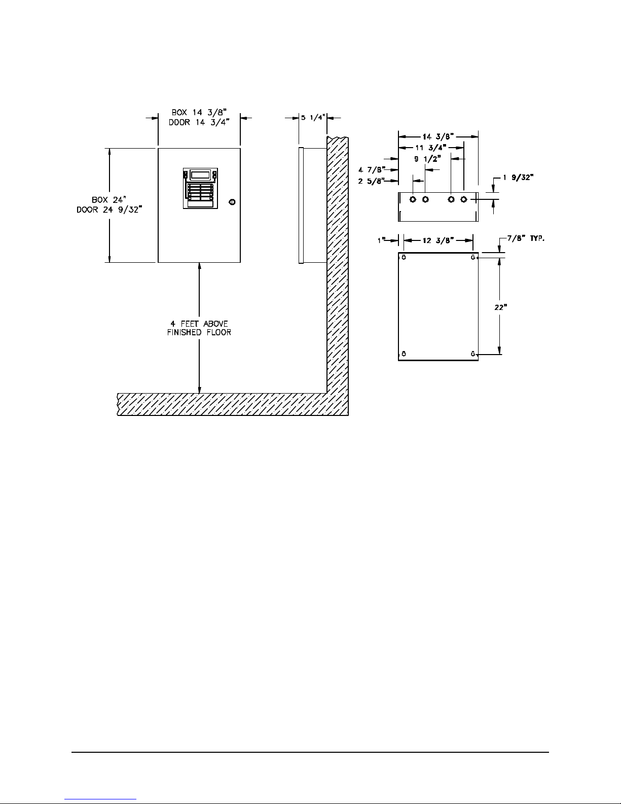
A. Surface Mounting Instructions - 12530
To mount the enclosure:
1. Mount the enclosure at a convenient height for viewing indicators and operating switches.
2. Use four #10 lag screws (not supplied) to secure the control unit to the wall. The screw type and
length must support the control unit, options and battery set.
Note: You may need a different screw type, depending on the wall material.
3. The 12408 Auxiliary Power Supply or battery enclosure may be mounted immediately below the main
enclosure, close nipple, allowing a minimum of 1 inch in between the enclosures for clearance
between the doors. Keeping the wire run to the control unit short will keep the voltage drop to a
minimum.
P/N 447203 Issue I IV-2
Page 30

12530/12540 OWNER'S MANUAL
B. Surface Mounting Instructions - 12540
To mount the enclosure:
1. Mount the enclosure at a convenient height for viewing indicators and operating switches.
2. Use four #10 lag screws (not supplied) to secure the control unit to the wall. The screw type and
length must support the control unit, options and battery set.
Note: You may need a different screw type, depending on the wall material.
3. The 12408 Auxiliary Power Supply or battery enclosure may be mounted immediately below the main
enclosure, close nipple, allowing a minimum of 1 inch in between the enclosures for clearance
between the doors. Keeping the wire run to the control unit short will keep the voltage drop to a
minimum.
P/N 447203 Issue I IV-3
Page 31
12530/12540 OWNER'S MANUAL
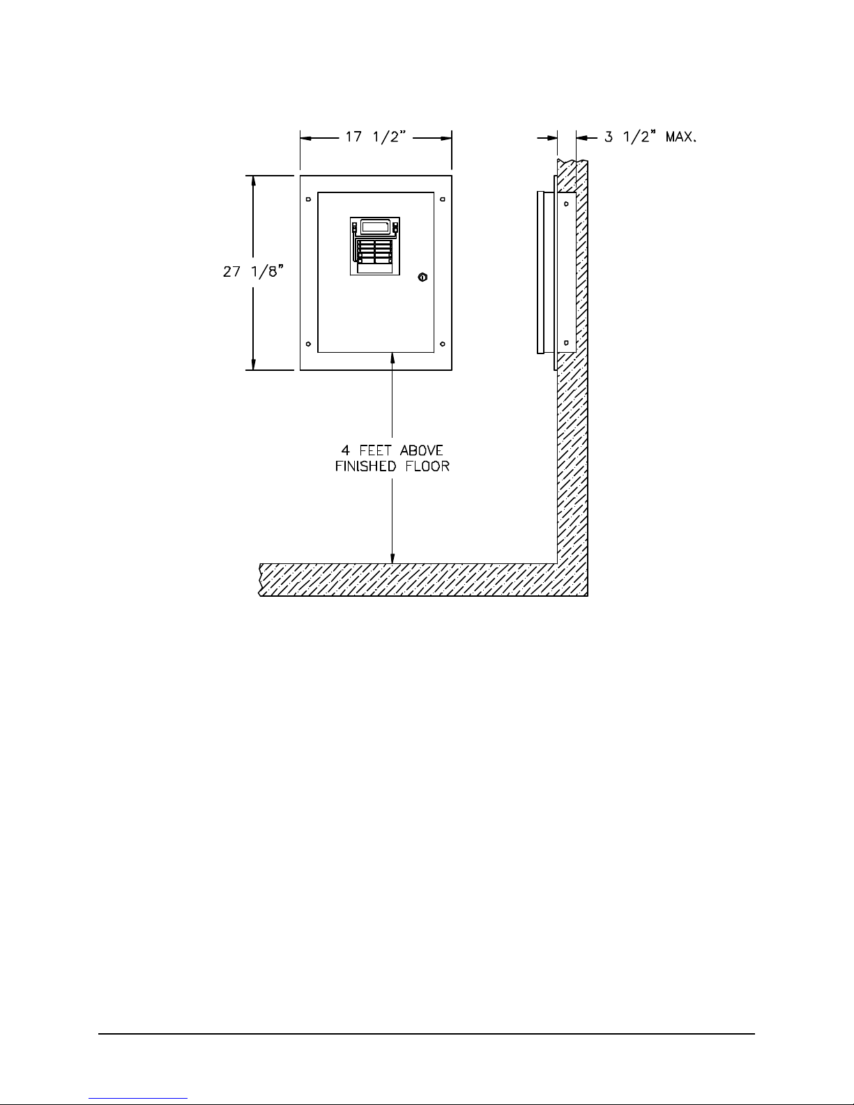
C. Semi-Flush Mounting Instructions - 12530
To mount the enclosure:
1. Mount the enclosure at a convenient height for viewing indicators, and operating switches.
2. Use four #10 lag screws (not supplied) to secure the control unit to the wall. The screw type and
length must support the control unit, options and battery set.
Note: You may need a different screw type, depending on the wall material.
3. The back-box can be mounted up to 3 1/2 inches into the wall. Place the semi-flush trim around the
back-box and affix to the wall with four #10 x 3/4 inch wood screws (provided with trim).
Note: You may need a different screw type, depending on the wall material.
4. The 12408 Auxiliary Power Supply or battery enclosure may be mounted immediately above or below
the main enclosure, close nipple, allowing a minimum of 3 inches in between the enclosures for
clearance between the semi-flush trims. Keeping the wire run to the control unit short will keep the
voltage drop to a minimum.
P/N 447203 Issue I IV-4
Page 32
12530/12540 OWNER'S MANUAL
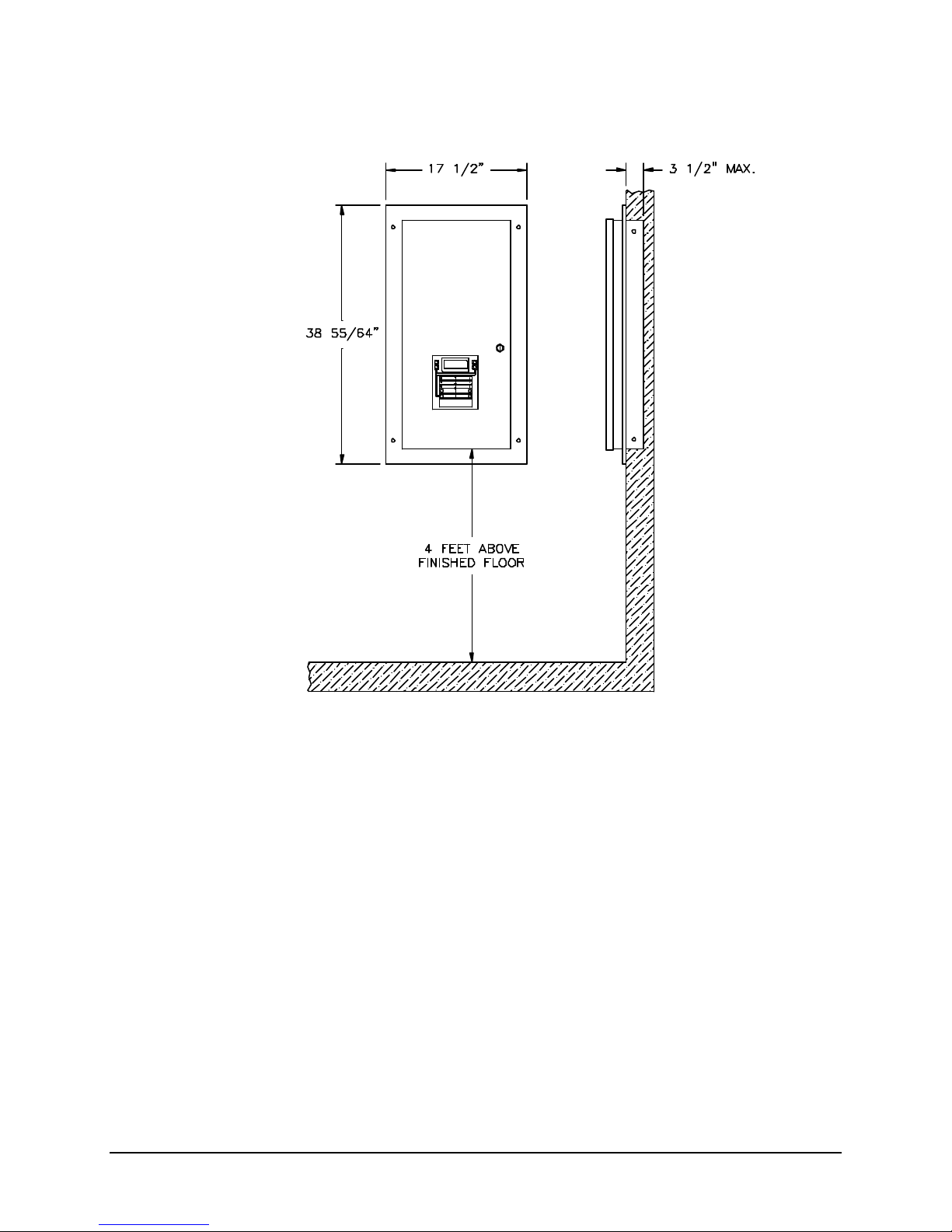
D. Semi-Flush Mounting Instructions - 12540
To mount the enclosure:
1. Mount the enclosure at a convenient height for viewing indicators, and operating switches.
2. Use four #10 lag screws (not supplied) to secure the control unit to the wall. The screw type and
length must support the control unit, options and battery set.
Note: You may need a different screw type, depending on the wall material.
3. The back-box can be mounted up to 3 1/2 inches into the wall. Place the semi-flush trim around the
back-box and affix to the wall with four #10 x 3/4 inch wood screws (provided with trim).
Note: You may need a different screw type, depending on the wall material.
4. The 12408 Auxiliary Power Supply or battery enclosure may be mounted immediately above or below
the main enclosure, close nipple, allowing a minimum of 3 inches in between the enclosures for
clearance between the semi-flush trims. Keeping the wire run to the control unit short will keep the
voltage drop to a minimum.
P/N 447203 Issue I IV-5
Page 33
12530/12540 OWNER'S MANUAL
E. Knock-Outs
1. Prepare the enclosure for electrical wiring, break out the appropriate conduit entry points. Note the
wiring diagram requirements for non-power limited and power limited wiring separation.
2. Attach conduit (if required) and run wires as required. Label each field cable for future reference.
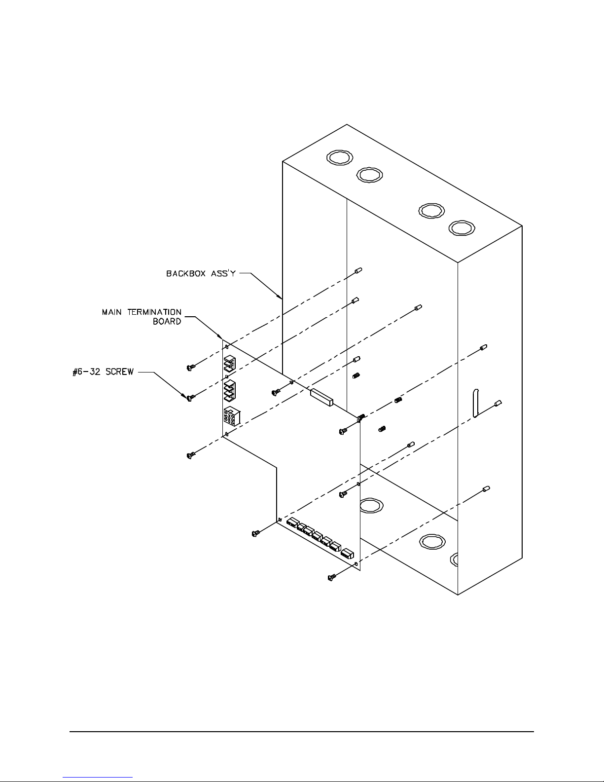
F. Main Termination Board Installation
1. Secure the board to the back of enclosure using eight of the provided #6-32 x 1/4 screws (P/N 29529-
11).
P/N 447203 Issue I IV-6
Page 34
12530/12540 OWNER'S MANUAL
TB17
TB18P1TB5
TB8
1
1-11-
C-
C
NAC
NAC
P1
+
+
X-
P7
P1
Loop Board
Cable Assembly
G. Loop Driver Board Installation
Spacers (4)
TB1
A
NAC
A
B-
NAC
B
TB3
DD
+
-
P2
P3
P4
OUT
X
X-
1
-
OUT
X
2
-
TB7
OUT
IN
2
OUT
22
IN
2-
TB9
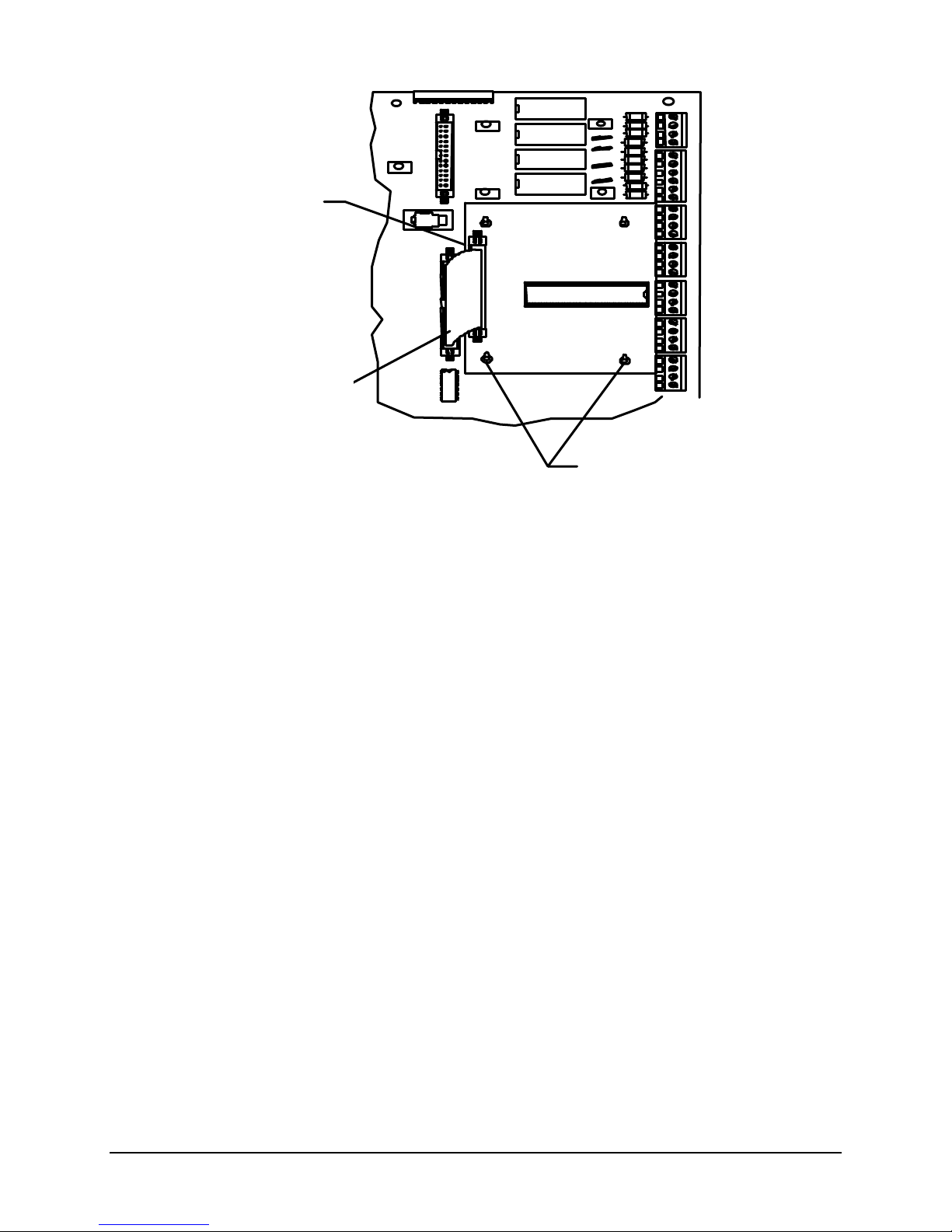
1. Set jumpers J1-J5 to the “F” position for Faraday or to “S” for System Sensor addressable devices.
2. Using four Plastic Spacers (P/N 943165), attach the Loop Driver Board (P/N 413765) to the Main
Termination Board.
3. Plug the Cable Assembly (P/N 446653) into connector P1 of the Loop Driver Board and to connector
P7 of the Main Termination Board.
P/N 447203 Issue I IV-7
Page 35
12530/12540 OWNER'S MANUAL
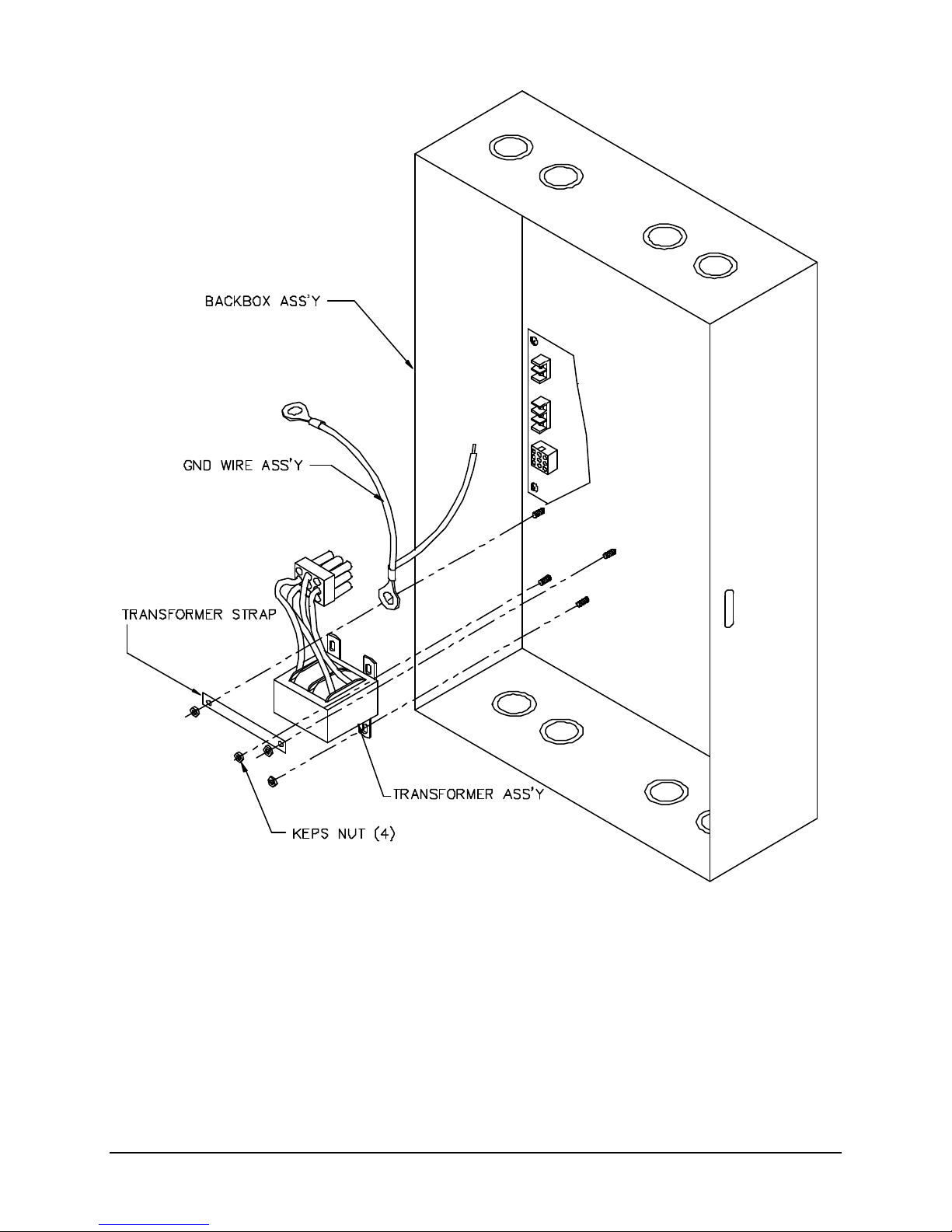
H. Transformer Mounting
1. Place Ground Wire Assembly (P/N 413394) on top left transformer mounting stud as shown.
2. Place Transformer Strap (P/N 444818) across the top transformer mounting studs and loosely place
keps nuts (P/N 18965) to secure.
3. Slide the top mounting brackets of the Transformer Assembly (P/N 413649 or 413650) under the
transformer strap with the bottom mounting brackets over the bottom studs.
4. Place keps nuts (P/N 18965) on the bottom studs. Tighten all keps nuts.
5. Plug the transformer assembly into connector P9 on the Main Termination Board.
6. Place the stripped ground wire into the ground terminal of TB4 and secure.
P/N 447203 Issue I IV-8
Page 36
12530/12540 OWNER'S MANUAL
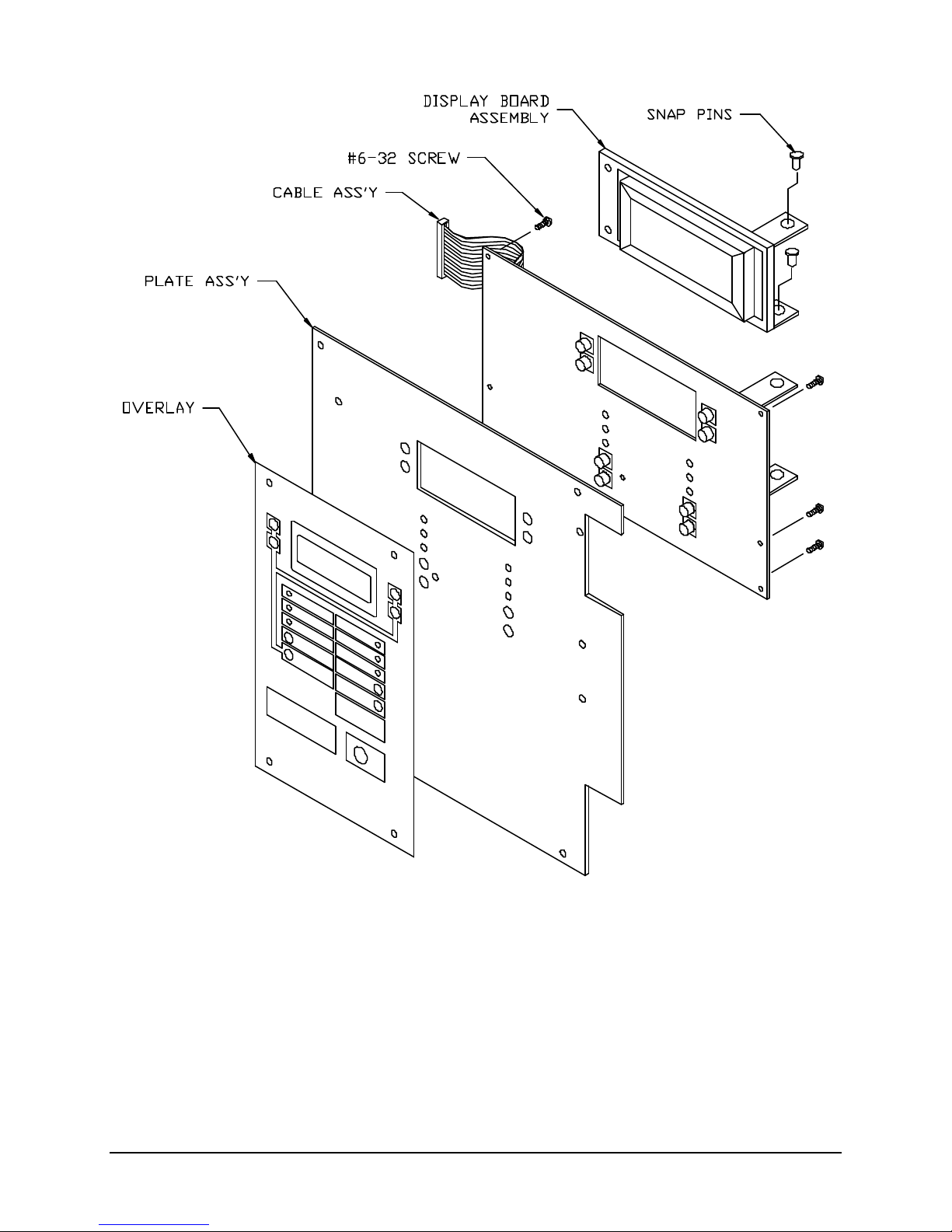
I. Front Pl ate Assembly
1. Secure Main Logic Board (P/N 413764) to Plate Assembly using six #6-32x1/4” screws (P/N29529-
11).
2. Apply Overlay (P/N 447206) to Plate Assembly (P/N 446668).
3. Using two snap pins (P/N 944043), attach the Display Board (P/N 413526) to the mounting brackets
on the Main Logic Board.
4. Plug the Cable Assembly (P/N 446649) into connector P2 of the Display Board and to connector P2
of the Main Logic Board.
P/N 447203 Issue I IV-9
Page 37
12530/12540 OWNER'S MANUAL
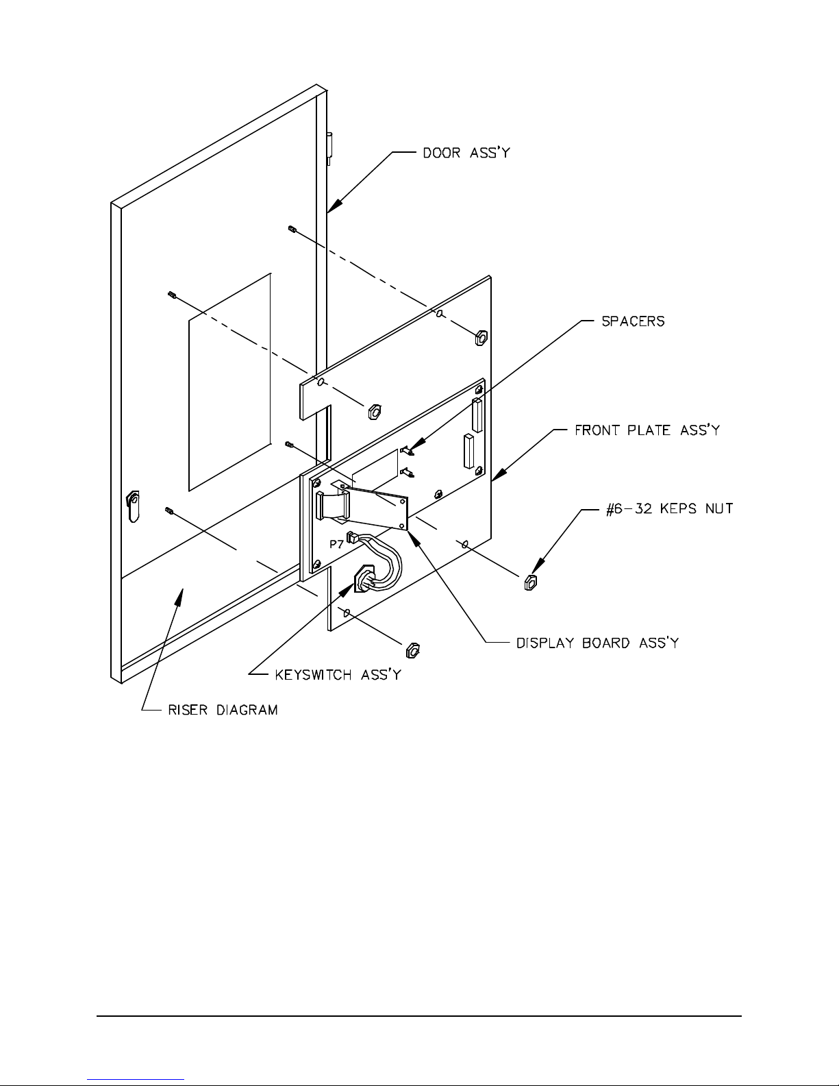
J. Front Plate Mounting
1. Secure the Front Plate Assembly to Door Assembly using four #6-32 keps nuts (P/N 18965).
2. Place the Keyswitch Assembly (P/N 413751) into the hole in the lower right corner of the Front Plate
Assembly. Secure with the attached nut and plug connector into P7 on the Main Logic Board.
3. Plug two Plastic Spacers (P/N 944023) into the holes at the right side of the display opening.
P/N 447203 Issue I IV-10
Page 38
12530/12540 OWNER'S MANUAL
K. Door Assembly
1. Place the Door Assembly onto hinges of the Back-box Assembly.
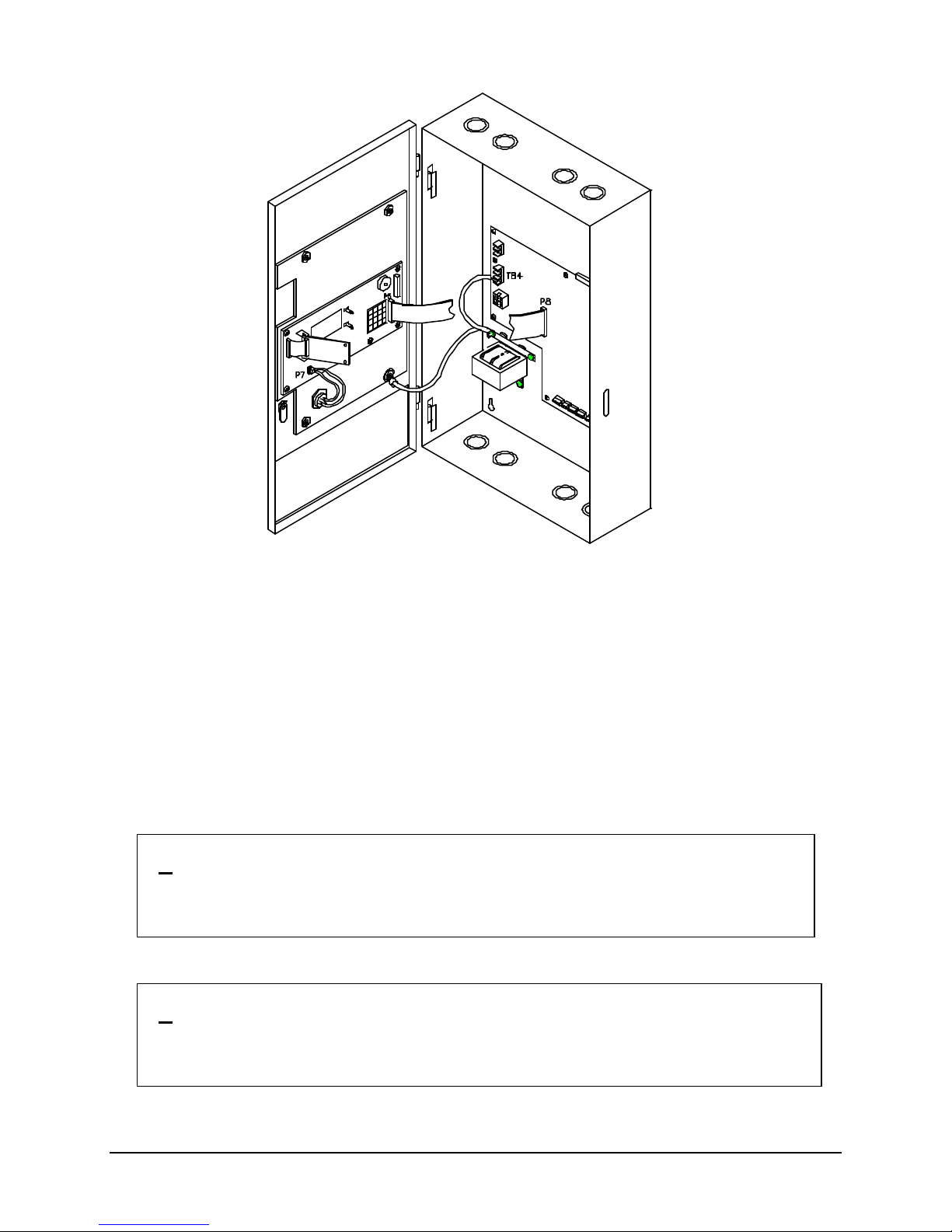
2. Plug the Cable Assembly (P/N 446052) into connector P8 of the Main Termination Board and to
connector P5 of the Main Logic Board.
3. Place the remaining ground wire under the mounting nut at the bottom right of the front plate.
L. AC Supply Connection
Wire the AC supply to terminal block TB4 on the main board. The supply should originate from a
separate, fused circuit. It should be provided with a breaker or other means of isolation.
Observe the wiring order -- the bottom terminal is ground and must be wired back to the electrical panel
ground (earth) bonding point or another good ground acceptable to the authority having jurisdiction and
the electrical inspector. The neutral wire must be taken back to the electrical panel neutral distribution
bar and must not be grounded.
/! \ WARNING: Dangerous voltages will be present on this terminal block and on
other components surrounding it and the transformer when the
AC supply is turned on. Do not touch.
M. Battery Installation
/! \ WARNING: Improper battery connections or shorting battery terminals may
damage the system and/or batteries and may cause personal
injuries.
P/N 447203 Issue I IV-11
Page 39

12530/12540 OWNER'S MANUAL
Place the batteries in the space provided in the bottom of the back-box. If larger than 10 AH battery set is
required, a separate enclosure must be used. The Faraday 14050 may be used for battery sets 18 AH
and smaller. The Faraday BE-1S may be used for battery sets 38 AH and smaller.
The control unit uses a 24V battery set. Connect the two 12V batteries (or four 6V batteries) in series
with #12 AWG wire, minimum. Route the battery leads to the left of the enclosure and up to the battery
termination block, TB2. The bat tery leads are not power-limited.
Observe polarity. Connect the B- terminal from the main termination board into the black or - terminal of
the battery set and the B+ terminal from the main termination board into the red or + terminal of the
battery set.
N. Powering the Control Unit
Apply AC power to the control unit AC POWER ON LED, SYSTEM TROUBLE LED, and the trouble
buzzer should be on.
O. Checking Supervised Circuits
To check the supervised circuits of the control unit:
1. Place a 4.7K ohm resistor (color-coded: yellow, violet, red) across each set of NAC terminals.
2. Push SYSTEM RESET button.
3. The SYSTEM TROUBLE LED, and the trouble buzzer should be off.
4. Discard 4.7K ohm resistors after initial testing is complete
P. Optional Modules
Follow the installation instructions provided in Appendix D.
Q. System Wiring
Before connecting the field wiring, check the wiring for opens, shorts, grounds and stray voltages.
WARNING: Damage may result if a high voltage insulation tester is
used on wiring while connected to the control unit.
Terminate the field wiring to the main board in accordance with the diagrams in Section V and the system
design documents.
NOTE: All wiring must be in accordance with local codes and the National Electrical Code. Use
only FPL, FPLR and/or FPLP as described in Article 760 of the National Electric Code.
R. Check System Operation
Check for proper operation of all the system functions. See Section II for Operation Instructions.
P/N 447203 Issue I IV-12
Page 40
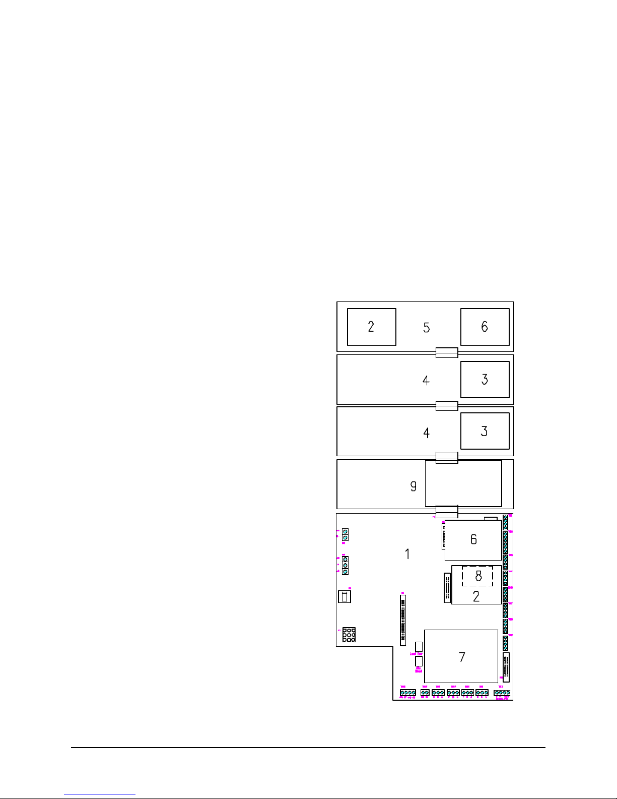
12530/12540 OWNER'S MANUAL
1. Main Termination Board
V. SYSTEM WIRING
Basic system wiring and detector siting must be in accordance with NFPA 72 or other instructions from
the appropriate local authority. Unit connections and limitations are as indicated on the wiring diagram
included below.
Devices that may be satisfactorily used with the control unit are shown in the compatible device listing in
Appendix B.
Wire reference data are included in Appendix A.
CONTROL UNIT WIRING OVERVIEW
The overall arrangement of boards in the control unit is shown in the following diagram.
2. 12522 Loop Driver Board
3. 12401A Class A Adapter
4. 12503 Conventional Expansion Board
5. 12505 Loop/Signal Expansion
6. 12504 Class A Adapter
7. 12402 Relay Board
8. 12511 Serial Isolation Board
9. 12513 DACT Expansion Module
P/N 447203 Issue I V-1
Page 41
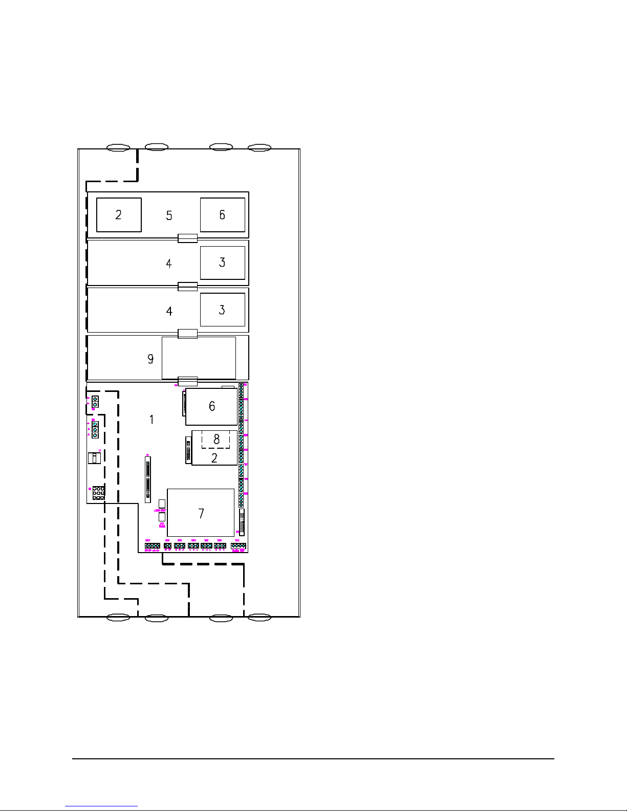
12530/12540 OWNER'S MANUAL
A. Non-power limited - High Voltage
1. Main Termination Board
WIRING SEPARATION
All high voltage and non-power limited wiring must be kept separate from power limited wiring. A ¼”
separation must be maintained, with high voltage and non-power limited wiring running in separate
conduit openings from power limited wiring.
A
E C
F
(AC power) or B
B. Non-power limited - High Voltage
(AC power) or A
C. Power limited (or E or F or H)
D. Non-power limited
(Battery If external enclosure required)
E. Power limited (or C or F or H)
F. Power limited (or C or E or H)
G. Non-power limited
(Local Energy or Shunt City Tie)
H. Power limited (or C or E or F)
B H
D G
2. 12522 Loop Driver Board
3. 12401A Class A Adapter
4. 12503 Conventional Expansion Board
5. 12505 Loop/Signal Expansion
6. 12504 Class A Adapter
7. 12402 Relay Board
8. 12511 Serial Isolation Board
9. 12513 DACT Expansion Module
P/N 447203 Issue I V-2
Page 42
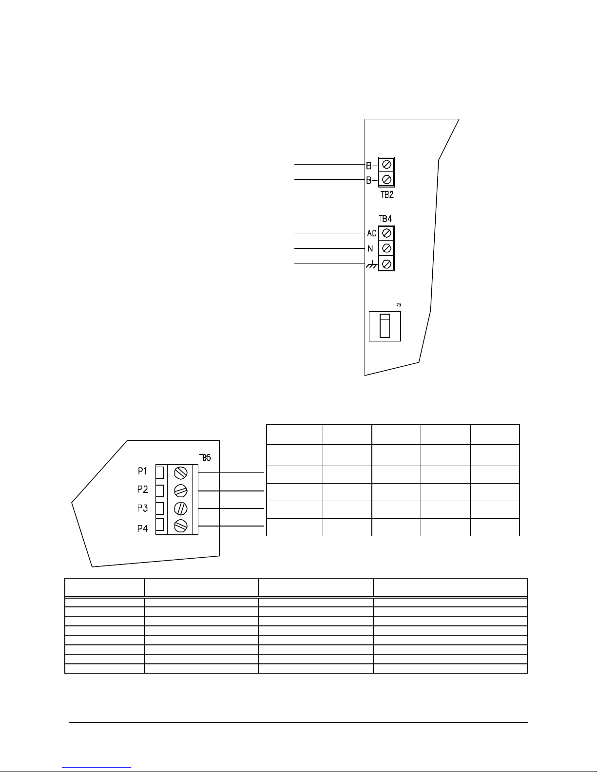
12530/12540 OWNER'S MANUAL
24V Battery Set
120VAC/240VAC 50/60Hz
AC
Keep All Non-Power Limited Wiring
B+
Control unit
Printer
Printer or
Printer or
Computer
PRIMARY AND SECONDARY POWER WIRING
The AC main connections and the battery connections must be made along the left-hand side of the
board. Route all high voltage and non-power limited wiring together and away from power limited wiring.
(7 to 38AH)
Supervised
Non-Power Limited
B-
3A/1.5A max., Supervised
Non-Power Limited
N
GND
Separate from Power Limited Wiring
PRINTER WIRING
The printer connections must be made along the right-hand side of the board. The RS232 output
provides event data for connection to a printer, terminal or computer.
Faraday RPR-100
DIP Switch Settings
SW-1 ON-Language (Unlashed 0) ON-Odd Parity ON-4800 bps
SW-2 OFF-Language (Unlashed 0) ON-No Parity OFF-4800 bps
SW-3 OFF-Language (Unlashed 0) ON-8 Bit Data ON-4800 bps
SW-4 OFF-Form Length (11”) ON-Ready/Busy OFF-DSR Inactive
SW-5 ON-Form Length (11”) ON-Diagnostic-Circuit Test ON-Buffer Threshold (32 bytes)
SW-6 ON-Auto Line Feed (ON) ON-Normal Print Mode OFF-Busy Signal Timing (1S)
SW-7 ON-Data Bits (8) ON-DTR ON-DTR Signal (space after power on)
SW-8 ON-Front Panel (Disable) ON-DTR OFF-Not Used
Control Board Serial Board
Function
Male
CTS DTR 8 20 4
TXD RXD 2 3 2
RXD TXD 3 2 3
GND GND 5 7 5
Function
Terminal
9-Pin
Terminal
Male
25-Pin
Settings: 4800 bps, 8 data bits, 1 stop bit, no parity
Switch Bank 1
Serial Board
Switch Bank 2
Female
9-Pin
P/N 447203 Issue I V-3
Page 43
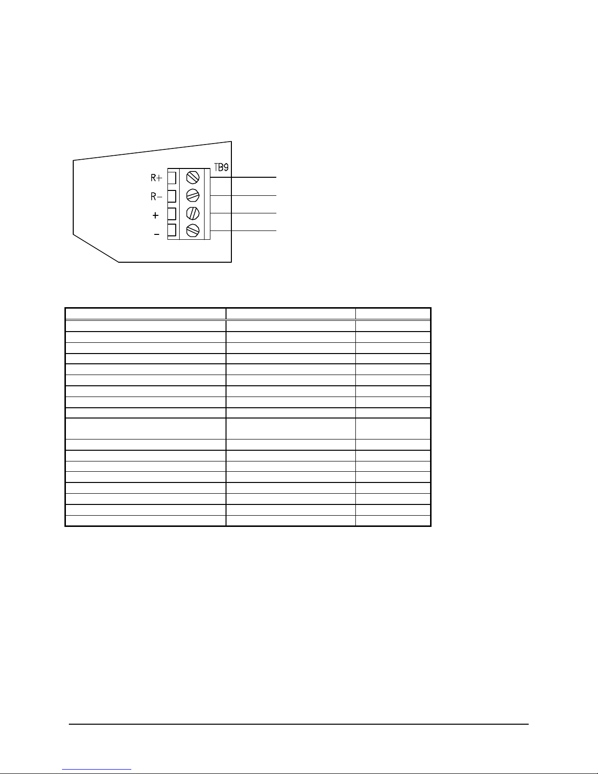
12530/12540 OWNER'S MANUAL
Auxiliary Power Output
AUXILIARY POWER OUTPUT WIRING
The right-hand edge of the main termination board provides for resettable and non-resettable auxiliary
power connections. An additional output is at the bottom of the main termination board.
0.9A max.@24VDC nominal,
System Power Requirement Calculations
Device Item Max.(Amps) Total (Amps)
12530/12540 Control Unit 0.400 0.400
Addressable Device Circuit Power # of Devices X 0.0002 Amps
Auxiliary Power Outputs * Depends on devices installed
12522 Loop Driver Board 0.022
12503 Conventional Expansion Board ____ X 0.075
12504 Class A Adapter ____ X 0.080
12505 Loop/Signal Expansion 0.135
12506 Remote LCD Annunciator * ____ X 0.030
12507/12508 Serial Relay Unit * ____ X 0.170 + ____ X 0.160
12509/12510 Serial Annunciator Unit * ____ X 0.040 + ____ X 0.005
12511 Serial Isolation Board 0.038
12513 DACT Expansion Module 0.054
12523 Network Interface Board 0.085
12526 Iso. Network Interface Board 0.093
12401A Class A Adapter ____ X 0.005
12402 Alarm Relay Board 0.037
15128 Digital Alarm Communicator 0.180
Total must not exceed 0.9 Amps
Auxiliary Power Supply
* Connect a 12408 auxiliary supply when power requirement calculation indicates that an additional
source is required. For further information, refer to the installation instructions in Appendix D. An
external trouble monitor is provided to indicate a trouble condition during an auxiliary power supply failure.
Unsupervised, Power Limited
(Maximum current of all auxiliary power outputs,
DACT and relay board is 0.9A.)
+lamp current
Battery Size Calculations
For calculation of battery size requirements see appendix A.
P/N 447203 Issue I V-4
Page 44
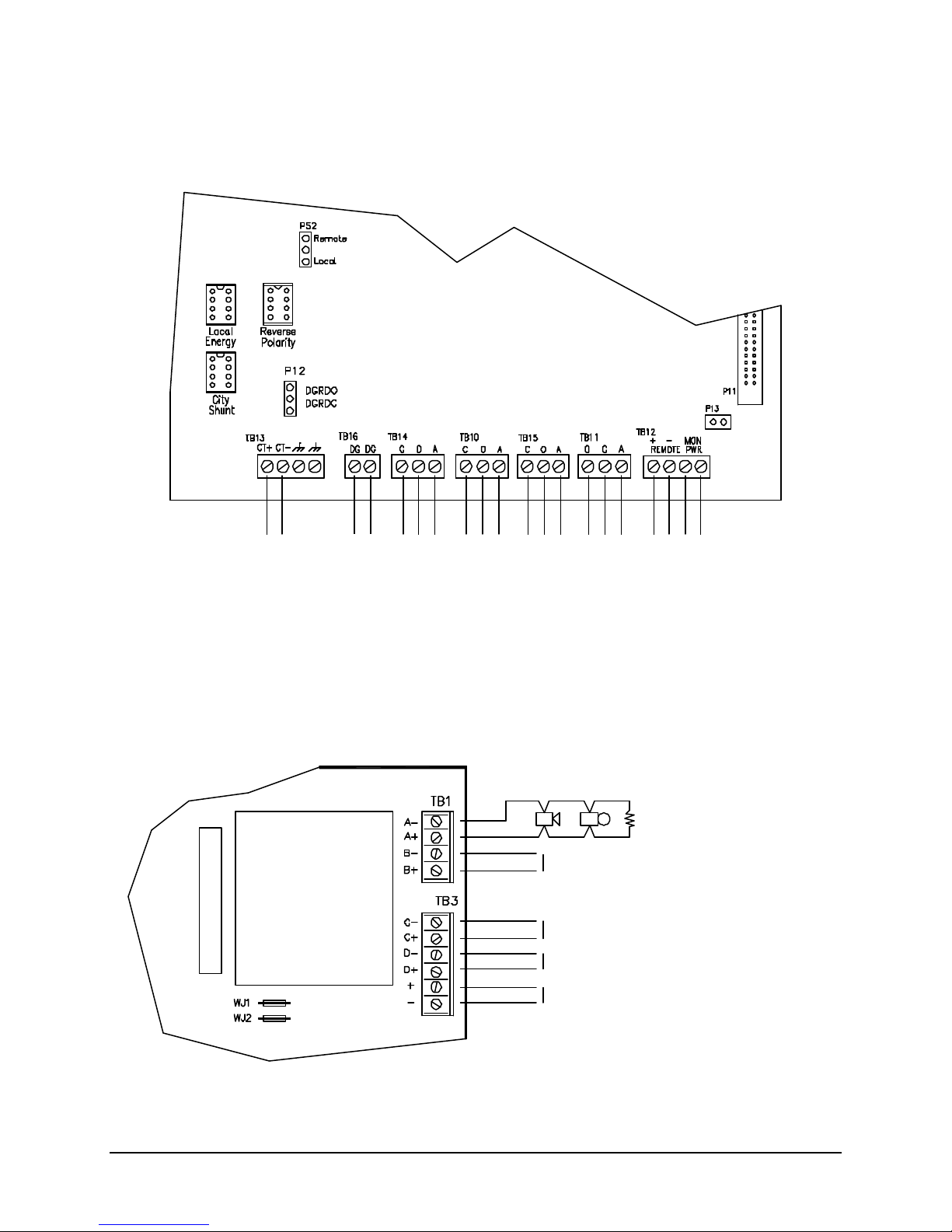
12530/12540 OWNER'S MANUAL
Notification Appliance Circuit
4.7K 1/2W
-
+
See Typical
See Typical
NAC Rating:
The maximum current for control
See Typical
Optional external 24VDC
Optional 12504
External Trouble Monitor
Status Relay Contacts
Auxiliary Power Output 0.9A max.@24VDC
Processor
City Tie
Power
CITY TIE AND STATUS RELAYS WIRING
The lower edge of the main termination board provides for connection of city tie, status relay contacts,
auxiliary power connections and external trouble monitor.
Connections
Failure
Alarm
(Shown in normal standby condition)
2A@30VDC, 0.5A@30VAC max, Resistive
For Power Limited Source, Unsupervised
Failure
Trouble Supervisory
+ -
Supervised, Power Limited
If P13 removed, monitors
normally closed contact
nominal, Unsupervised, Power Limited
(Maximum current of all auxiliary power
outputs, DACT and relay board is 0.9A.)
NAC WIRING
At the right hand side of the main board the terminal blocks are used for the connection of notification
appliances. Four individual NACs marked A through D are provided and the polarity shown is when the
NAC is activated.
Polarity shown in activated condition
Class A Adapter
Faraday P/N 10812
Supervised, Power Limited
See Owner’s Manual for
Wiring above
Wiring above
Wiring above
nominal input for NACs 3 & 4,
3 Amp. max.
Use 12408 Auxiliary Power Supply.
Cut jumper WJ1 & 2 to enable
Alarm Voltage: 24VDC nominal
Max. Alarm Current: 1.5A
Max. Ripple: 1.5VAC
Max. Wire Voltage Drop: 1.0VDC
Max. Standby Current: 3.4mA
NOTE:
unit and appliances is 4.4A
Style Y, Class B
Compatible Devices
P/N 447203 Issue I V-5
Page 45
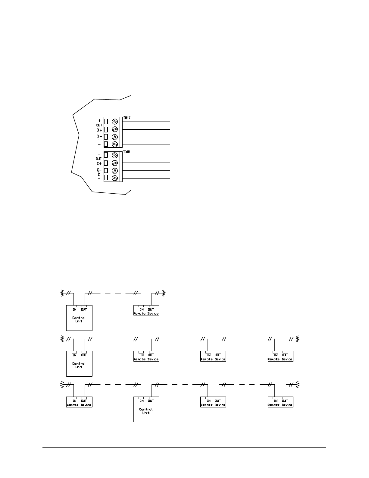
12530/12540 OWNER'S MANUAL
Serial Interface Circuit
RS485 COMMUNICATIONS CIRCUIT
The RS485 communication circuit can address up to 16 standard annunciators and/or 8 remote
processors to drive graphic annunciation or relay modules. Devices on the circuit may be connected up
to 4000 feet from the control unit. At the right side of the main termination board the terminal blocks are
used for the connection of remote serial devices.
Remote Device Power
When connecting devices on the RS485 communications circuit, a limited amount of current is available
from the control unit. If more current supply is required for the connected devices, auxiliary power must
be provided to each insufficiently powered device. Each address on the circuit must be fully powered
from either control unit or auxiliary power (no combined source can be configured).
24VDC nominal, 0.9A max.
Wire Resistance-25 ohms/line (4000’ max)
Wire Type-Twisted Pair for data
Supervised, Power Limited
See Owner’s Manual for Compatible Devices
Remote Device Data
When connecting devices on the RS485 communications circuit, the data wires must be daisy chained
and with no T-taps to preserve the integrity of the data. Each end (two places) must be terminated with a
120 ohm termination resistor. The following diagrams show the proper wiring.
P/N 447203 Issue I V-6
Page 46
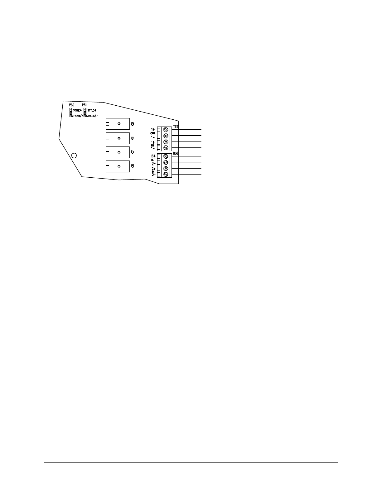
12530/12540 OWNER'S MANUAL
Addressable Device Circuit
ADDRESSABLE DEVICE CIRCUIT
The basic configuration of the 12530/12540 control unit includes two addressable device circuits. The
control unit can be programmed for operation with Faraday or System Sensor addressable devices.
These are polled by the control unit every few seconds and input or output functions communicated to
determine device status or function. The control unit monitors all device addresses for alarm and trouble
conditions.
See Owner’s Manual for Compatible Devices
Style 4 or 6/7 Operation
(set jumpers P50 & P51 for proper style)
24VDC nominal
Wire Resistance-20 ohms/line
Supervised, Power Limited
Addressable Device Wiring Diagrams
Proper connections for UL Listed compatible addressable devices are indicated below. Refer also to the
instruction sheets packed with each device.
Sensors and modules may be wired together according to several NFPA defined wiring styles. The wiring
style that is appropriate for your installation should be determined from the relevant building codes and
the Authority Having Jurisdiction.
P/N 447203 Issue I V-7
Page 47
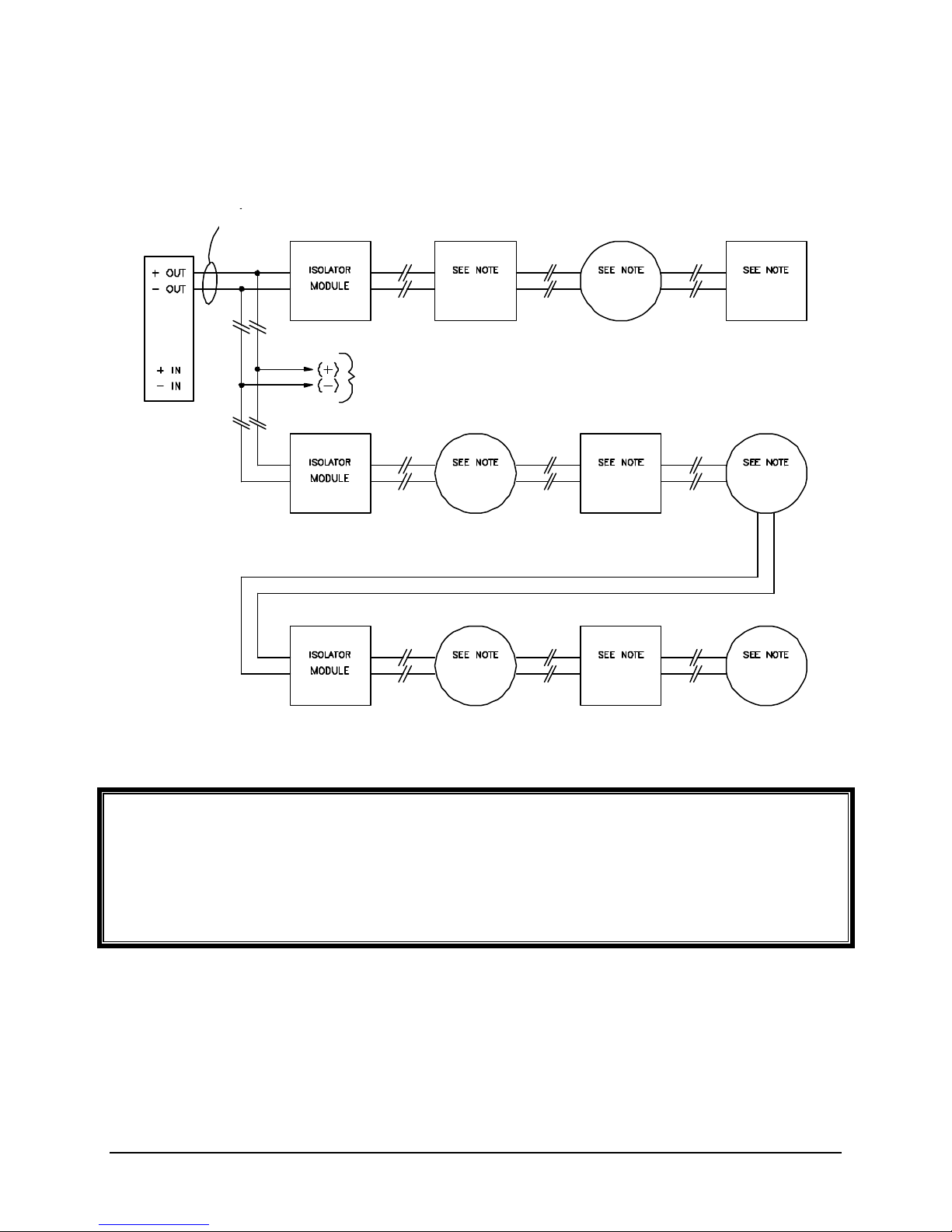
12530/12540 OWNER'S MANUAL
SUPERVISED,
TO OPTIONAL
BRANCH(ES) OF
Style 4 wiring permits branching of circuit connections. The control equipment supervises modules
because they are active and must respond periodically to the control units interrogation.
ADDRESSABLE DEVICE CIRCUIT
WIRING / OPERATION COMPARABLE TO NFPA STYLE “4”
POWER LIMITED
LOOP CIRCUIT
Note:
Faraday Addressable Devices:
Detectors, Monitor Modules, or Control Modules up to a maximum of 60 devices per addressable
device circuit. Maximum of 20 devices per Isolator Module. Maximum of 12 Isolator Modules per
addressable device circuit.
System Sensor Addressable Devices:
Sensors, Monitor Modules, or Control Modules up to a maximum of 99 Sensors and 99 Modules
per addressable device circuit. Recommended maximum of 25 devices per Isolator Module.
P/N 447203 Issue I V-8
Page 48
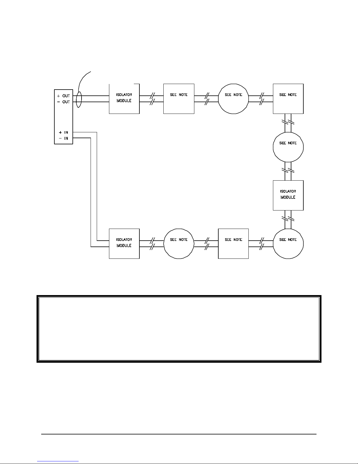
12530/12540 OWNER'S MANUAL
SUPERVISED,
Style 6 provides redundant communication paths.
ADDRESSABLE DEVICE CIRCUIT
WIRING / OPERATION COMPARABLE TO NFPA STYLE “6”
POWER LIMITED
Note:
Faraday Addressable Devices:
Detectors, Monitor Modules, or Control Modules up to a maximum of 60 devices per addressable
device circuit. Maximum of 20 devices between Isolator Modules. Maximum of 12 Isolator
Modules per addressable device circuit.
System Sensor Addressable Devices:
Sensors, Monitor Modules, or Control Modules up to a maximum of 99 Sensors and 99 Modules
per addressable device circuit. Recommended maximum of 25 devices between Isolator
Modules.
P/N 447203 Issue I V-9
Page 49
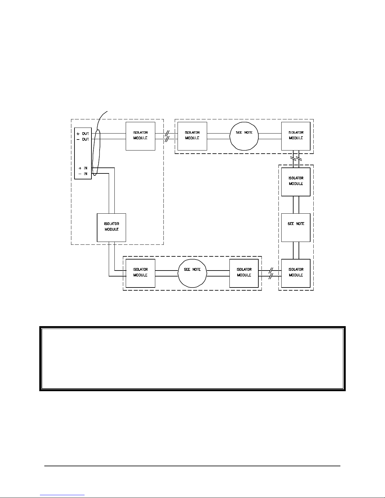
12530/12540 OWNER'S MANUAL
EACH CIRCUIT
CONDUIT.
EACH DEVICE MUST HAVE
SUPERVISED,
EACH DEVICE MUST HAVE
EACH DEVICE MUST HAVE
Style 7 may be used where it is required that a single break or short in the circuit does not cause any
modules to stop functioning.
ADDRESSABLE DEVICE CIRCUIT
WIRING / OPERATION COMPARABLE TO NFPA STYLE “7”
TWO ASSOCIATED
ISOLATOR MODULES WITH
WIRING ENCLOSED IN
POWER LIMITED
MUST HAVE TWO
ASSOCIATED
ISOLATOR
MODULES WITH
WIRING
ENCLOSED IN
CLOSED NIPPLED
CLOSED NIPPLED CONDUIT.
Note:
Faraday Addressable Devices:
Not applicable to Style 7 wiring.
System Sensor Addressable Devices:
Sensors, Monitor Modules, or Control Modules up to a maximum of 99 Sensors and 99 Modules
per addressable device circuit. Maximum of 1 device between Isolator Modules. When using the
9298 or 9299 Isolator Base, it will be wired in place of a 9160 and the addressable sensor shown
in the wiring above (one 9160 Isolator is required per sensor with an isolator base).
TWO ASSOCIATED
ISOLATOR MODULES WITH
WIRING ENCLOSED IN
CLOSED NIPPLED CONDUIT.
TWO ASSOCIATED
ISOLATOR MODULES WITH
WIRING ENCLOSED IN
CLOSED NIPPLED CONDUIT.
P/N 447203 Issue I V-10
Page 50

12530/12540 OWNER'S MANUAL
Addressable/Analog Sensors
Each sensor uses a sensor address between 01 and 99 on an addressable device circuit. The device is
regularly scanned by the control unit and checked for its current sensor status. The control unit will
interpret and respond to the analog data as programmed. Each time the device is scanned the integral
red visible LEDs will flash. In the event of an alarm condition the red LEDs will illuminate and latch on.
8406 Low Profile Photoelectric Sensor with Thermal
The 8406 Low Profile Photoelectric Sensor (System Sensor 2251T) allows programmable analog
sensitivity with fixed thermal temperature of 135° F. Requires a 9189, 9296 or 9298 base (System
Sensor B210LP, B224RB or B224BI).
8407 or 8408 Thermal Sensor
The 8407 (System Sensor 5251P) or 8408 (System Sensor 5251RP) has a fixed operating temperature of
135° F. The 8408 has a fixed operating temperature of 135° F with rate-of-rise detection. Requires a
9189, 9296 or 9298 base (System Sensor B210LP, B224RB or B224BI).
9152 Photoelectronic Sensor
The 9152 (System Sensor 2551B) allows programmable analog sensitivity. Requires a 9155, 9156,
9181, 9297 or 9299 base (System Sensor B501B, B501BH, B501, B524RB or B524BI).
9153 Photoelectronic Sensor with Thermal
The 9153 (System Sensor 2551THR) allows programmable analog sensitivity with fixed thermal
temperature of 135° F. Requires a 9155, 9156, 9181, 9297 or 9299 base (System Sensor B501B,
B501BH, B501, B524RB or B524BI).
9154 or 9182 Thermal Sensor
The 9154 (System Sensor 5551B) has a fixed operating temperature of 135° F. The 9182 (System
Sensor 5551R) has a fixed operating temperature of 135° F with rate-of-rise detection. Requires a 9155,
9156, 9181, 9297 or 9299 base (System Sens or B501B, B501BH, B501, B524RB or B524BI).
9163 Ionization Sensor
The 9163 (System Sensor 1551B) allows programmable analog sensitivity. Requires a 9155, 9156,
9181, 9297 or 9299 base (System Sensor B501B, B501BH, B501, B524RB or B524BI).
9187 Low Profile Photoelectronic Sensor
The 9187 Low Profile Photoelectric Sensor (System Sensor 2251) allows programmable analog
sensitivity. Requires a 9189, 9296 or 9298 base (System Sensor B210LP, B224RB or B224BI).
9188 Low Profile Ionization Sensor
The 9188 Low Profile Ionization Sensor (System Sensor 1251) allows programmable analog sensitivity.
Requires a 9189, 9296 or 9298 base (System Sensor B210LP, B224RB or B224BI).
NOTE: The devices are set at the factory for address 00. This is a default code. During
installation set address to the predetermined address code.
P/N 447203 Issue I V-11
Page 51

12530/12540 OWNER'S MANUAL
9155, 9156 or 9181 Addressable/Analog Bases
The 9155 or 9181 (System Sensor B501B or B501) base is a standard design for use with an
addressable/analog sensor. Provides connection to an optional remote LED. The 9181 is flange-less for
special mounting applications.
The 9156 (System Sensor B501BH) audible sensor base is designed for use with an addressable/analog
sensor. The 9156 provides means to obtain a local audible alarm at the specific sensor location. Once
the 9156's associated sensor has latched into the alarm state, the integral horn in the 9156 will sound. It
will remain on until the sensor is successfully reset. A regulated power supply is required for the integral
horn.
9189 Low Profile Addressable/Analog Base
The 9189 (System Sensor B210LP) Low Profile base is used with the 9187 and 9188 addressable/analog
Low Profile sensors. Provides connection to an optional remote LED.
P/N 447203 Issue I V-12
Page 52
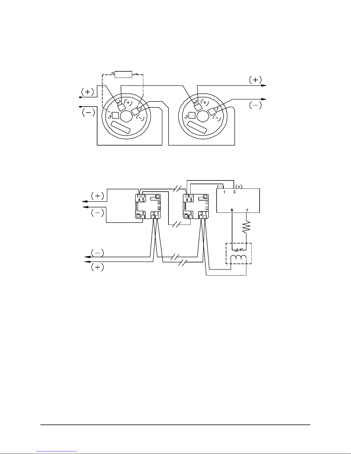
12530/12540 OWNER'S MANUAL
24VDC
Optional Faraday 9180 Remote Alarm
To Next
Faraday PM6849 EOL relay
From Addressable
Faraday 9155, 9181 or 9189 BASE:
Faraday 9156 BASE:
47K EOL Resistor
Faraday 9157/9158 Monitor Module
From Addressable
Typical Base Wiring Diagram (9155, 9181 & 9189)
LED (System Sensor RA400Z)
Device Circuit
Typical Horn Base Wiring Diagram (9156)
(System Sensor B501B, B501 or B210LP)
Addressable
Device
(System Sensor B501BH)
(System Sensor M500MB/M501M)
(9157 module shown)
M500MB
Device Circuit
Supplied with unit
Power
Supply
(See Note 4)
(System Sensor A77-716B)
Notes:
1. This wiring diagram shows only general information about this device. For specific wiring and
installation information, read the instructions provided with the device.
2. Wire Size: In alarm, no more than 3.0V drop from power supply to end of power supply loop.
3. For power supply supervision use an EOL relay with a 9157 or 9158 monitor module as shown.
(Relay contact shown with power applied)
4. From the control unit auxiliary power output or an external 24VDC regulated power supply that must
be power limited and listed for Fire Protective Signaling Use.
P/N 447203 Issue I V-13
Page 53
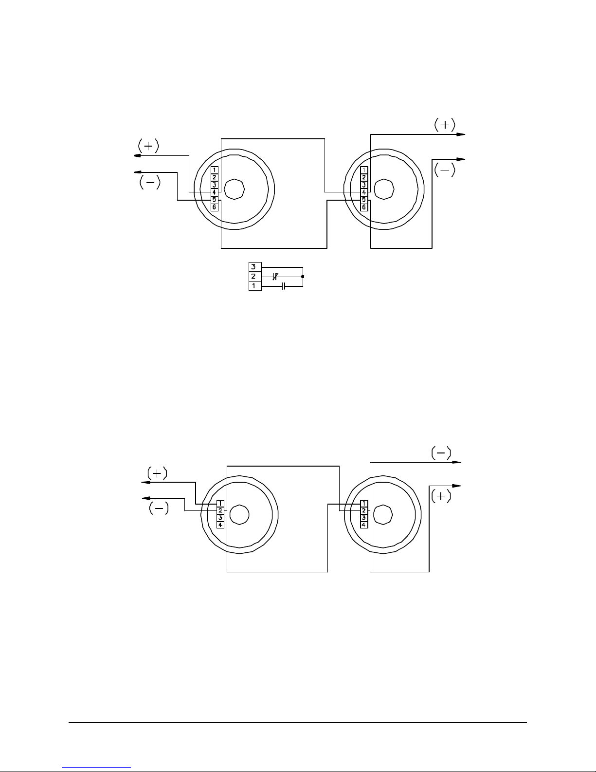
12530/12540 OWNER'S MANUAL
To Next
From Addressable
Faraday 9296 or 9297 BASE:
To Next
From Addressable
Faraday 9298 or 9299 BASE:
9296 & 9297 Relay Base
The 9297 (System Sensor B524RB) is designed for use with an addressable/analog sensor and provides
an alarm relay contact. The 9296 (System Sensor B224RB) is used with Low Profile sensors.
(System Sensor B524RB or B224RB)
Addressable
Device
Device Circuit
Notes:
1. This wiring diagram shows only general information about this device. For specific wiring and
installation information, read the instructions provided with the device.
9298 & 9299 Isolator Base
The 9299 (System Sensor B524BI) is designed for use with an addressable/analog sensor and provides
short circuit isolation. The 9298 (System Sensor B224BI) is used with Low Profile sensors.
(System Sensor B524BI or B224BI)
Addressable
Device
Device Circuit
Notes:
1. This wiring diagram shows only general information about this device. For specific wiring and
installation information, read the instructions provided with the device.
P/N 447203 Issue I V-14
Page 54
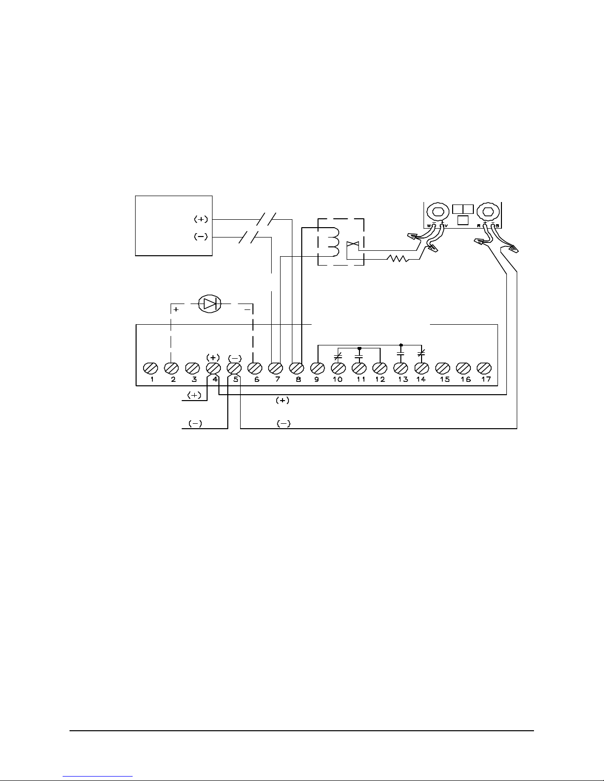
12530/12540 OWNER'S MANUAL
24VDC
Faraday PM6849 EOL relay
Faraday 9161 Duct Housing:
47K EOL Resistor
Faraday 9157/9158 Monitor Module
From Addressable
Optional Faraday 9180 Remote Alarm LED
To Next
9161 Duct Housing for Addressable/Analog Sensors
The 9161 (System Sensor DH500AC/DC) is designed for use with an addressable/analog Ion or Photo
sensor. The 9161 is designed for 120VAC, 240VAC, 24VAC, or 24VDC to operate auxiliary functions.
Two "Form C" relay contacts are available. The LEDs on the sensor illuminate to indicate an alarm.
Remote alarm indication is made possible by utilizing the 9180 remote alarm LED unit.
TYPICAL WIRING DIAGRAM FOR A 9161 DUCT HOUSING
FOR ADDRESSABLE ANALOG SENSOR
(System Sensor M500MB/M501M)
(9158 module shown)
(System Sensor A77-716B)
Power
Supply
(See Note 4)
(System Sensor RA400Z)
Device Circuit
(System Sensor DH500AC/DC)
Addressable
Device
Supplied with unit
Notes:
1. This wiring diagram shows only general information about this device. For specific wiring and
installation information, read the instructions provided with the device.
2. Wire Size: In alarm, no more than 3.0V drop from power supply to end of power supply loop.
3. For power supply supervision use an EOL relay with a 9157 or 9158 monitor module as shown.
(Relay contact shown with power applied)
4. From the control unit auxiliary power output or an external 24VDC regulated power supply that
must be power limited and listed for Fire Protective Signaling Use.
5 9180 Remote LE D and Auxiliary Control contacts will not function without separate power.
6 Relay contacts are rated at 10 Amps maximum at 30VDC, 10 Amps maximum at 277VAC, 1/2
HP at 240VAC and 360VA at 240VAC.
P/N 447203 Issue I V-15
Page 55
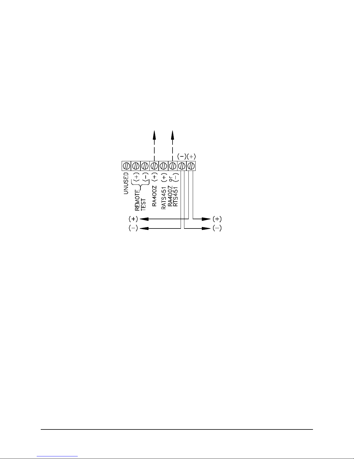
12530/12540 OWNER'S MANUAL
Faraday 9179 Duct Housing:
From Addressable
Optional Faraday 9180 Remote Alarm LED:
To Next
9179 Duct Housing for Addressable/Analog Sensors
The 9179 (System Sensor DH500) is designed for use with an addressable/analog Ion or Photo sensor.
The LEDs on the sensor illuminate to indicate an alarm. Remote alarm indication is made possible by
utilizing the 9180 remote alarm LED unit. The 9167 remote test station may be used, if separate power is
supplied.
TYPICAL WIRING DIAGRAM FOR A 9179 DUCT HOUSING
FOR ADDRESSABLE/ANALOG SENSOR
(System Sensor RA400Z)
(System Sensor DH500)
Device Circuit
Addressable
Device
Notes:
1. This wiring diagram shows only general information about this device. For specific wiring and
installation information, read the instructions provided with the device.
2 The 9167 remote test station switch will not function without separate power. (See typical wiring
diagram for a 9161 duct housing for wiring of separate power with supervision).
P/N 447203 Issue I V-16
Page 56
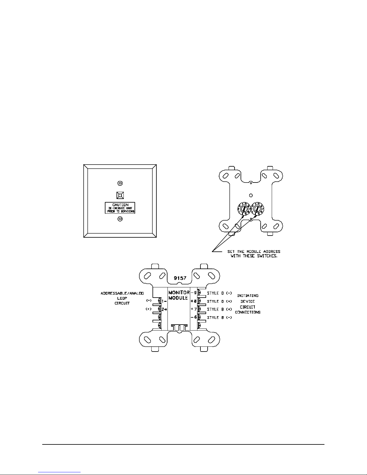
12530/12540 OWNER'S MANUAL
Addressable Modules
Zone Monitor Module (9157)
The 9157 (System Sensor M500MB) monitor module provides (1) Style "B" (2-wire) initiating circuit or (1)
Style "D" (4-wire) initiating circuit for normally open dry contact fire alarm and supervisory (tamper)
devices. The 9157 is designed to mount directly inside a 4" square junction box. The 9157 monitor
module may be used to monitor a single unit or "zone" of units of "4-wire" (separately powered) smoke
detectors, manual stations, waterflow switches, tamper (supervisory) switches or other dry, normally open
contact initiation devices.
The 9157 uses a module address between 01 and 99 on an addressable device circuit. The 9157
module is regularly scanned by the control unit and checked for its current monitored device(s) status (i.e.
open (trouble), normal (EOL), shorted (alarm)). Each time the 9157 is scanned the front visible red LED
will flash. Once the control unit has received the status data it will interpret and respond to this data as
programmed. In the case of an alarm status or Style "D" open circuit, the front visible red LED will
illuminate and latch on the appropriate 9157 module(s) until the system is successfully reset.
NOTE: The devices are set at the factory for address 00. This is a default code. During
installation set address to the predetermined address code.
P/N 447203 Issue I V-17
Page 57
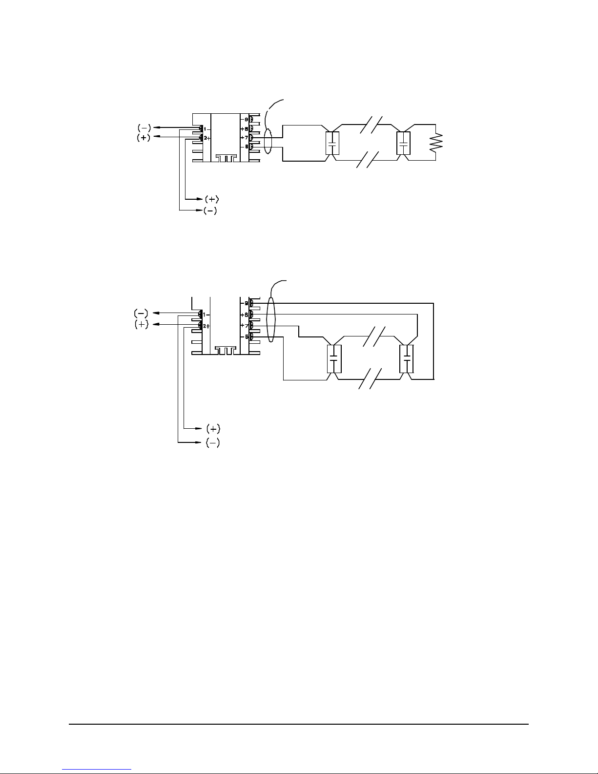
12530/12540 OWNER'S MANUAL
Faraday 9157 Monitor Module:
47K EOL Resistor
From Addressable
To Next
Supervised
Faraday 9157 Monitor Module:
From Addressable
To Next
Supervised
See NFPA 72 for maximum quantity
See NFPA 72 for maximum quantity
CONFIGURATION OF 9157 MONITOR MODULE
TYPICAL CONVENTIONAL STYLE “B” (“2-WIRE”) CONTACT DEVICE INITIATING CIRCUIT
(System Sensor M500MB)
Device Circuit
Addressable
Device
Power limited
Supplied with unit
of devices per initiating device circuit.
CONFIGURATION OF 9157 MONITOR MODULE
TYPICAL CONVENTIONAL STYLE “D” (“4-WIRE”) CONTACT DEVICE INITIATING CIRCUIT
(System Sensor M500MB)
Device Circuit
Power limited
Addressable
Device
of devices per initiating device circuit.
Notes:
1. This wiring diagram shows only general information about this device. For specific wiring and
installation information, read the instructions provided with the device.
2. Do not mix Fire & Supervisory (Tamper) Devices on the same initiating device circuit.
3. Initiating Circuit Requirements:
Maximum wire length: 2500 Ft.
Maximum wire resistance: 20 Ohms
Maximum alarm current: 230uA
4. Do not put “2-Wire” (Zone Powered) Smoke Detectors on Monitor Module Initiating loop.
5. See Article 370 of the N.E.C. for proper box depth.
P/N 447203 Issue I V-18
Page 58
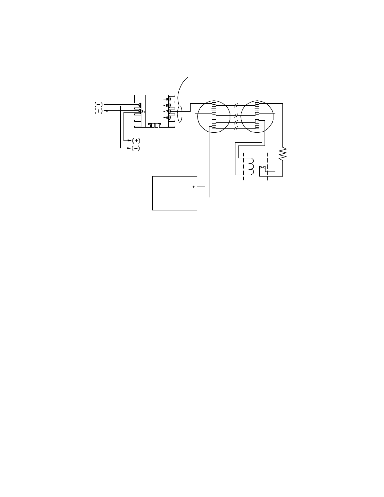
12530/12540 OWNER'S MANUAL
Faraday 9157 Monitor Module:
47K EOL Resistor
From Addressable
To Next
Supervised
24VDC
Faraday PM6849 EOL relay
See NFPA 72 for maximum quantity
CONFIGURATION OF 9157 MONITOR MODULE
TYPICAL WIRING DIAGRAM FOR CONVENTIONAL
“4-WIRE” (SEPARATELY POWERED) SMOKE DETECTORS STYLE “B” (“2-WIRE”)
Power limited
(System Sensor M500MB)
Device Circuit
Addressable
Device
of devices per initiating device circuit.
Supplied with unit
Power
Supply
(See Note 7)
(System Sensor A77-716B)
Notes:
1. This wiring diagram shows only general information about this device. For specific wiring and
installation information, read the instructions provided with the device.
2. Do not mix Fire & Supervisory (Tamper) Devices on the same initiating device circuit.
3. Initiating Circuit Requirements:
Maximum wire length: 2500 Ft.
Maximum wire resistance: 20 Ohms
Maximum alarm current: 230uA
4. Do not put “2-Wire” (Zone Powered) Smoke Detectors on Monitor Module Initiating loop.
5. See Article 370 of the N.E.C. for proper box depth.
6. For power supply supervision use an E.O.L. relay as shown (relay contact shown with power
applied).
7. From the control unit resettable auxiliary power supply output or an external 24VDC regulated
power supply that must be power limited and listed for Fire Protective Signaling Use.
P/N 447203 Issue I V-19
Page 59
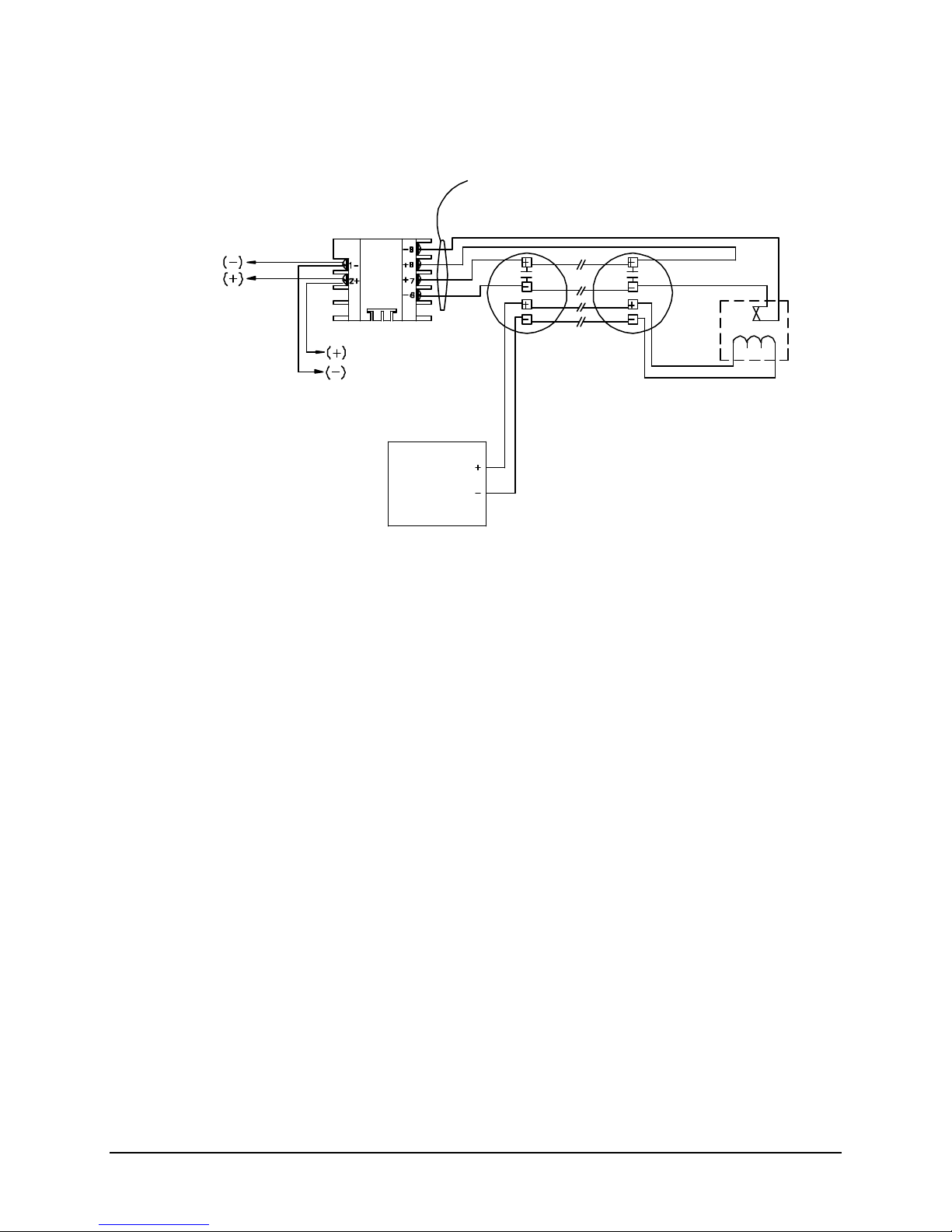
12530/12540 OWNER'S MANUAL
Faraday 9157 Monitor Module:
From Addressable
To Next
Supervised
24VDC
Faraday PM6849 EOL relay
See NFPA 72 for maximum quantity
CONFIGURATION OF 9157 MONITOR MODULE
TYPICAL WIRING DIAGRAM FOR CONVENTIONAL
“4-WIRE” (SEPARATELY POWERED) SMOKE DETECTORS STYLE “D” (“4-WIRE”)
Power limited
(System Sensor M500MB)
Device Circuit
Addressable
Device
Power
Supply
(See Note 7)
of devices per initiating device circuit.
(System Sensor A77-716B)
Notes:
1. This wiring diagram shows only general information about this device. For specific wiring and
installation information, read the instructions provided with the device.
2. Do not mix Fire & Supervisory (Tamper) Devices on the same initiating device circuit.
3. Initiating Circuit Requirements:
Maximum wire length: 2500 Ft.
Maximum wire resistance: 20 Ohms
Maximum alarm current: 230uA
4. Do not put “2-Wire” (Zone Powered) Smoke Detectors on Monitor Module Initiating loop.
5. See Article 370 of the N.E.C. for proper box depth.
6. For power supply supervision use an E.O.L. relay as shown (relay contact shown with power
applied).
7. From the control unit resettable auxiliary power supply output or an external 24VDC regulated
power supply that must be power limited and listed for Fire Protective Signaling Use.
P/N 447203 Issue I V-20
Page 60
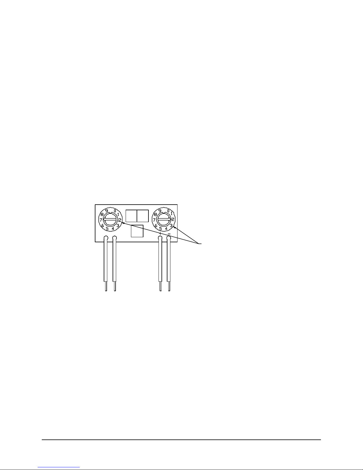
12530/12540 OWNER'S MANUAL
Addressable
Device Circuit
Initiating
Device Circuit
Set the device address
Yellow
Black
Red
Violet
Device Monitor Module (9158) ("Mini -Monitor")
The 9158 (System Sensor M501M) addressable mini-monitor module provides a Style "B" (2-wire)
initiating circuit for normally open dry contact fire alarm and supervisory (tamper) devices. The 9158's
small size and light weight design allows it to be installed inside a single gang box, or behind a device
being monitored without being rigidly mounted. The 9158 addressable mini-monitor module may be used
to monitor a single unit or a "zone" of units of "4-Wire" (separately powered) smoke detectors, manual
stations, waterflow switches, tamper (supervisory) switches or other dry, normally open contact initiation
devices.
NOTE: "2-Wire" (Zone Powered) Smoke detectors and initiation devices are not compatible.
The 9158 uses a module address between 01 and 99 on an addressable device circuit. The 9158 is
regularly scanned by the control unit and checked for its current monitored device(s) status (i.e. open
(trouble), normal (EOL), shorted (alarm)). Once the control unit has received the status data, it will
interpret and respond to this data as programmed.
9158 Monitor Module
(-)
(+)
(+)
(-)
with these switches.
(See note below)
NOTE: The devices are set at the factory for address 00. This is a default code.
During installation set address to the predetermined address code.
P/N 447203 Issue I V-21
Page 61
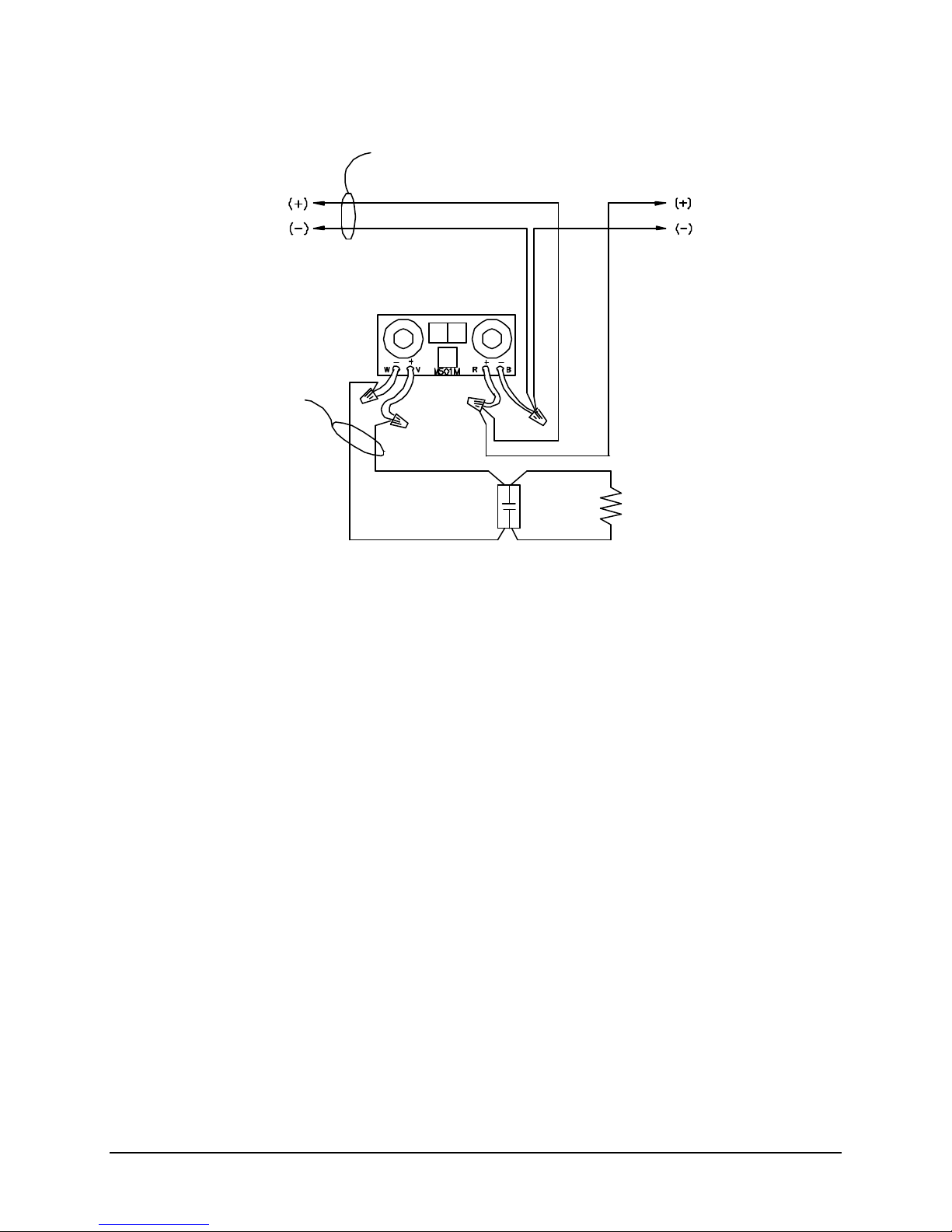
12530/12540 OWNER'S MANUAL
Faraday 9157 Monitor Module:
From Addressable
To Next
Supervised
See NFPA 72 for maximum quantity
47K EOL Resistor
Supervised
CONFIGURATION OF 9158 MONITOR MODULE
TYPICAL CONVENTIONAL STYLE “B” (“2-WIRE”) INITIATING CIRCUIT
Power limited
Device Circuit
(System Sensor M501M)
Power limited
Supplied with unit
of devices per initiating device circuit.
Addressable
Device
Notes:
1. This wiring diagram shows only general information about this device. For specific wiring and
installation information, read the instructions provided with the device.
2. Do not mix Fire & Supervisory (Tamper) Devices on the same initiating device circuit.
3. Initiating Circuit Requirements:
Maximum wire length: 2500 Ft.
Maximum wire resistance: 20 Ohms
Maximum alarm current: 230uA
4. Do not put “2-Wire” (Zone Powered) Smoke Detectors on Monitor Module Initiating loop.
5. See Article 370 of the N.E.C. for proper box depth.
P/N 447203 Issue I V-22
Page 62
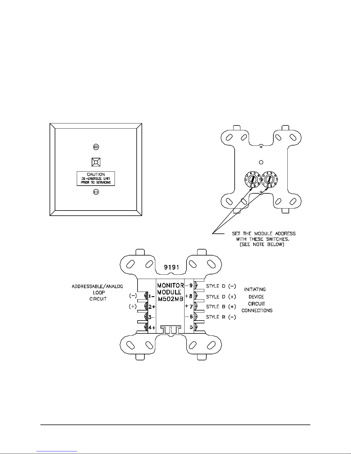
12530/12540 OWNER'S MANUAL
Interface Module (9191)
The 9191 (System Sensor M502M) addressable Interface Module allows the addressable device circuit to
interface and monitor two-wire conventional smoke detectors. All two-wire detectors being monitored
must be UL compatible with the module. The 9191 is addressed through the communication line of
intelligent systems. When the module is interrogated, it transmits the status of one zone of two-wire
detectors to an intelligent control unit. Status conditions are reported as normal, open, or alarm. The
interface module supervises the zone of detectors and the connection of an external power supply. Two
rotary decade switches allow setting module addresses from 01–99. A status LED indicator is provided
and is controlled by code command from the control unit. The module provides a magnetically activated
test switch for testing the module’s electronics and connections to the control unit.
NOTE: The devices are set at the factory for address 00. This is a default code.
During installation set address to the predetermined address code.
P/N 447203 Issue I V-23
Page 63
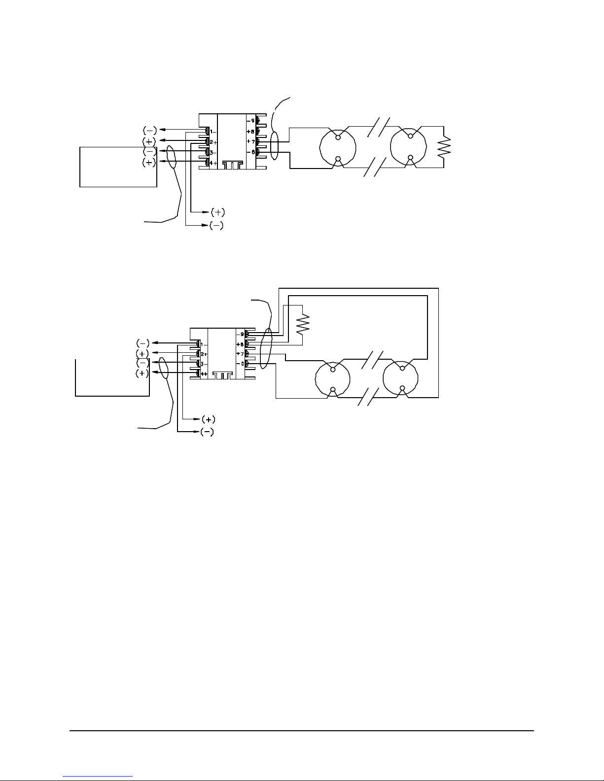
12530/12540 OWNER'S MANUAL
Faraday 9191 Monitor Module:
From Addressable
To Next
Supervised
3.9K EOL Resistor
Supervised
24VDC
Faraday 9191 Monitor Module:
From Addressable
To Next
Supervised
Supervised
24VDC
3.9K EOL Resistor
CONFIGURATION OF 9191 MONITOR MODULE
TYPICAL CONVENTIONAL STYLE “B” (“2-WIRE”) CONTACT DEVICE INITIATING CIRCUIT
Device Circuit
Power
Supply
(See Note 6)
Power limited
(System Sensor M502M)
Addressable
Device
Power limited
Supplied with unit
CONFIGURATION OF 9191 MONITOR MODULE
TYPICAL CONVENTIONAL STYLE “D” (“4-WIRE”) CONTACT DEVICE INITIATING CIRCUIT
Power limited
(System Sensor M502M)
Device Circuit
Power
Supply
(See Note 6)
Supplied with unit
Addressable
Power limited
Device
Notes:
1. This wiring diagram shows only general information about this device. For specific wiring and
installation information, read the instructions provided with the device.
2. Do not mix Fire & Supervisory (Tamper) Devices on the same initiating device circuit.
3. Initiating Circuit Requirements:
Maximum wire resistance: 25 ohms
Maximum alarm current: 92mA
4. Use only UL compatible “2-Wire” (Zone Powered) Smoke Detectors listed in the installation
instructions.
5. See Article 370 of the N.E.C. for proper box depth.
6. From the control unit resettable auxiliary power supply output or an external 24VDC regulated
power supply that must be power limited and listed for Fire Protective Signaling Use.
P/N 447203 Issue I V-24
Page 64
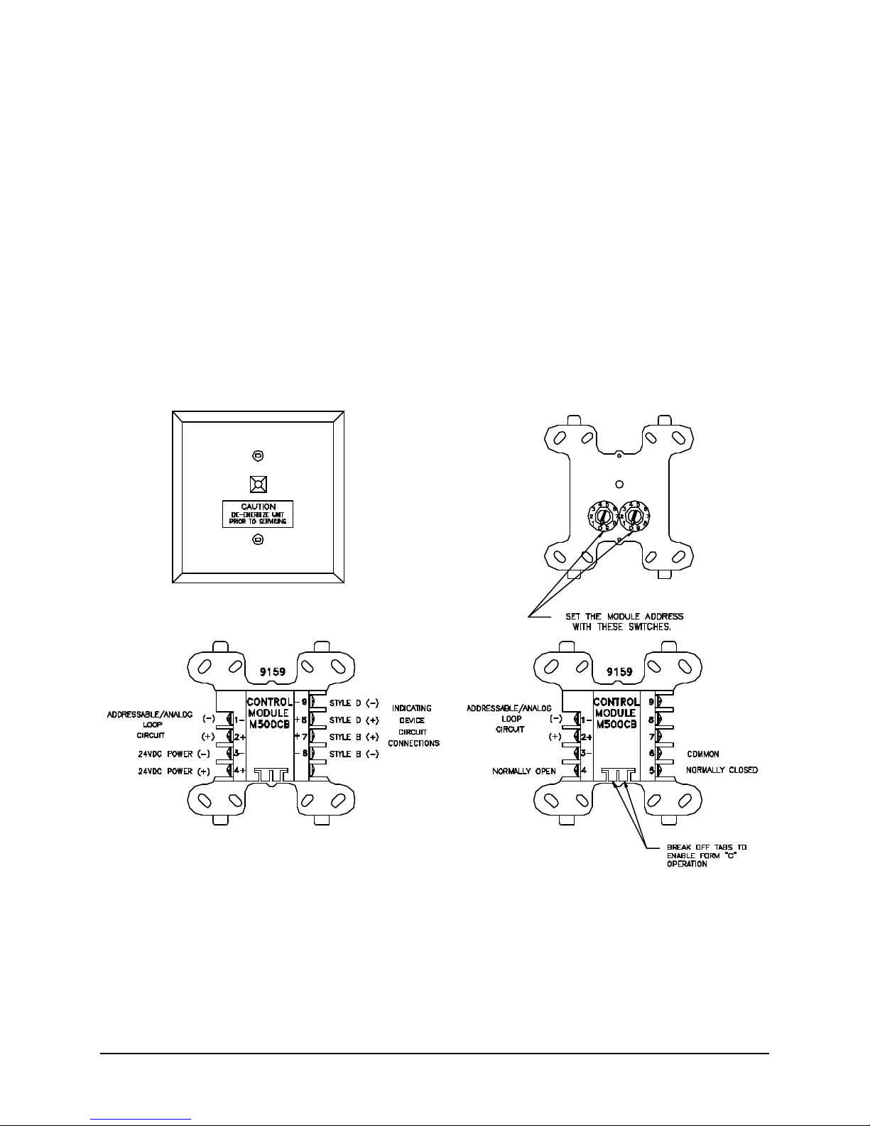
12530/12540 OWNER'S MANUAL
Control Module (9159)
The 9159 (System Sensor M500CH) addressable control module provides (1) Style "Y" (2-Wire") polarity
reversal notification appliance circuit or (1) "4-Wire" Class "A" (Style "Z") polarity reversal notification
appliance circuit or (1) dry form "C" contact output format. The selection of any (1) of these formats per
module can be made in the field via an integral programming tab. The 9159 is designed to mount directly
inside a 4" square junction box. When the 9159 control module is used drive conventional polarized
appliances and auxiliary devices, the operating power for the devices must be wired to the 9159
separately from an auxiliary power supply. The separate power circuit is then supervised by an E.O.L.
and monitor module combination relay in a similar fashion as a "4-Wire" (separately powered)
conventional smoke detector power circuit.
The 9159 uses a module address between 01 and 99 on an addressable device circuit. The 9159 is
regularly scanned by the control unit and checked for it's monitored device(s) status (i.e. open (trouble),
normal (EOL), shorted (trouble)). Each time the 9159 is scanned the front visible red LED will flash.
Once the control unit has received alarm status data it will interpret and respond to the data as
programmed thus activating any predetermined 9159 control module(s). When an associated 9159
operates, it's red LED will illuminate and the module will latch into the operated mode until reset.
NOTE: The devices are set at the factory for address 00. This is a default code.
During installation set address to the predetermined address code.
P/N 447203 Issue I V-25
Page 65
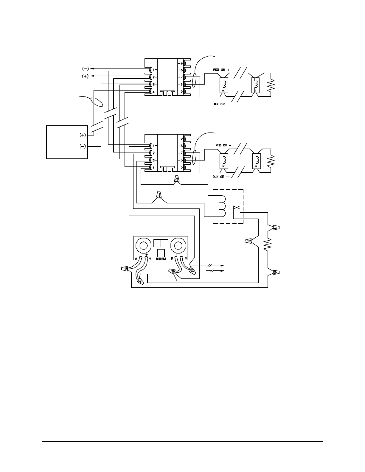
12530/12540 OWNER'S MANUAL
Faraday 9159 Control Module:
From Addressable
To Next
Supervised
See NFPA 72 for maximum quantity
47K EOL Resistor
47K EOL Resistor
Supervised
47K EOL Resistor
24VDC
Faraday PM6849 EOL relay
Faraday 9157/9158 Monitor Module
Supervised
CONFIGURATION OF 9159 CONTROL MODULE
TYPICAL CONVENTIONAL STYLE “Y” (“2-WIRE”) NOTIFICATION APPLIANCE CIRCUIT
Power limited
Device Circuit
Supplied with unit
Power limited
Power
Supply
(See Note 6)
Notes:
(System Sensor M500MB/M501M)
(9158 module shown)
(System Sensor M500CH)
of devices per initiating device circuit.
Power limited
Supplied with unit
(System Sensor A77-716B)
Supplied with unit
Addressable
Device
1. This wiring diagram shows only general information about this device. For specific wiring and
installation information, read the instructions provided with the device.
2. See owners manual for compatible appliances.
3. Notification Appliance Circuit Ratings:
Maximum alarm current: 1.0A
Maximum wire voltage drop: 1.9V
4. See Article 370 of the N.E.C. for proper box depth.
5. For power supply supervision use an E.O.L. relay as shown (relay contact shown with power
applied).
6. From the control unit auxiliary power supply output or an external 24VDC regulated power supply
that must be power limited and listed for Fire Protective Signaling Use.
P/N 447203 Issue I V-26
Page 66
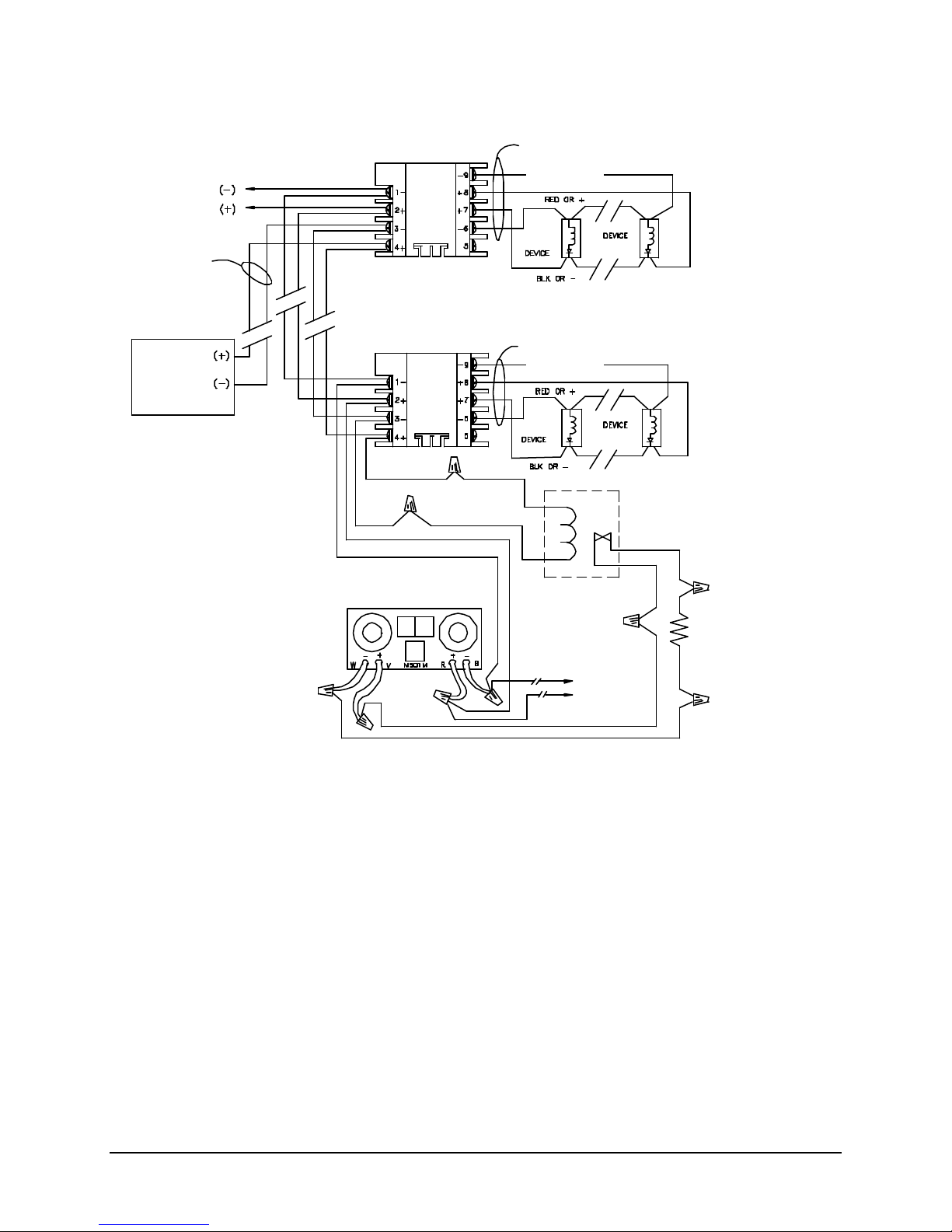
12530/12540 OWNER'S MANUAL
Faraday 9159 Control Module:
From Addressable
Supervised
See NFPA 72 for maximum quantity
47K EOL Resistor
Supervised
24VDC
Faraday PM6849 EOL relay
Faraday 9157/9158 Monitor Module
To Next
CONFIGURATION OF 9159 CONTROL MODULE
TYPICAL CONVENTIONAL STYLE “Z” (“4-WIRE”) NOTIFICATION APPLIANCE CIRCUIT
Power limited
Device Circuit
Power
Supply
(See Note??6)
Notes:
(System Sensor M500MB/M501M)
(9158 module shown)
(System Sensor M500CH)
of devices per initiating device circuit.
Power limited
(System Sensor A77-716B)
Supplied with unit
Addressable
Device
1. This wiring diagram shows only general information about this device. For specific wiring and
installation information, read the instructions provided with the device.
2. See owners manual for compatible appliances.
3. Notification Appliance Circuit Ratings:
Maximum alarm current: 1.0A
Maximum wire voltage drop: 1.9V
4. See Article 370 of the N.E.C. for proper box depth.
5. For power supply supervision use an E.O.L. relay as shown (relay contact shown with power
applied).
6. From the control unit auxiliary power supply output or an external 24VDC regulated power supply
that must be power limited and listed for Fire Protective Signaling Use.
P/N 447203 Issue I V-27
Page 67
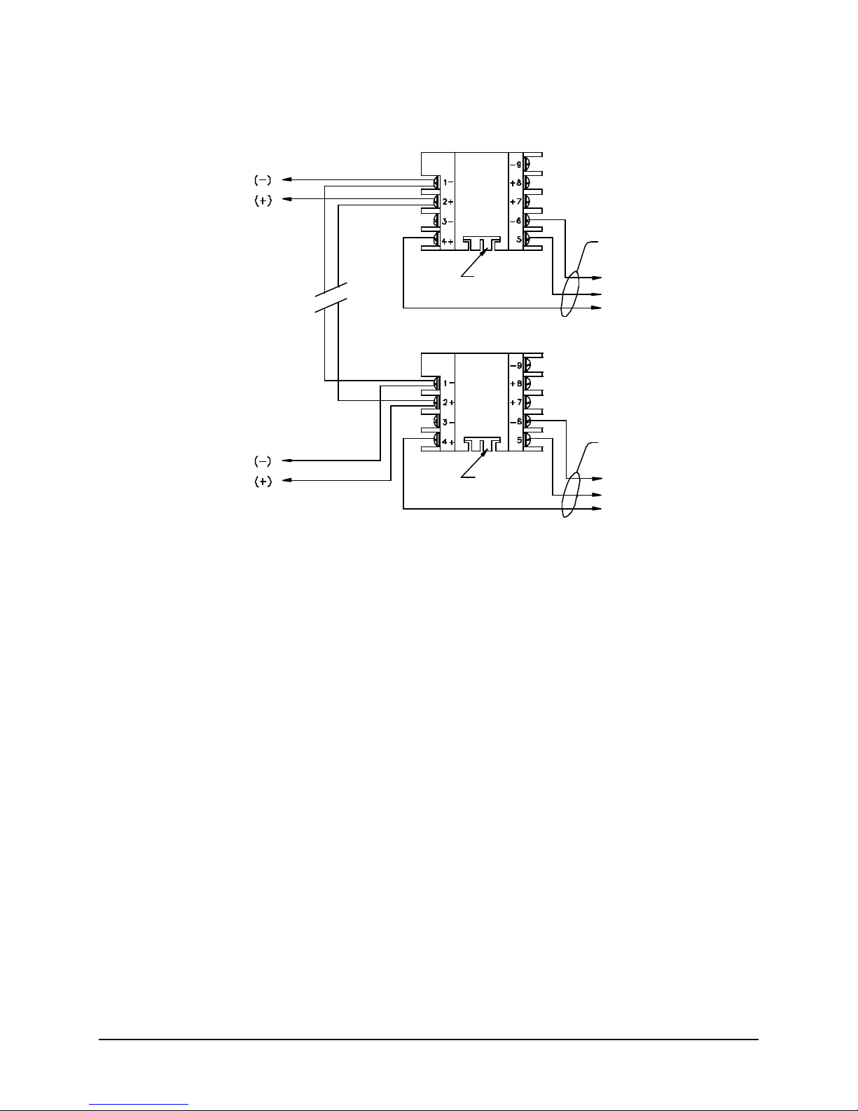
12530/12540 OWNER'S MANUAL
Faraday 9159 Control Module:
From Addressable
To Next
Break tabs
Common
Common
CONFIGURATION OF 9159 CONTROL MODULE
TYPICAL DRY FORM “C” CONTACT OUTPUT
Device Circuit
Not supervised
Normally closed
Normally open
(System Sensor M500CH)
Not supervised
Addressable
Device
Break tabs
Normally closed
Normally open
Notes:
1. This wiring diagram shows only general information about this device. For specific wiring and
installation information, read the instructions provided with the device.
2. Relay contact ratings:
Resistive: 2 A., 30VDC
Inductive: 1 A., 30VDC (0.6pf)
0.3A., 110VDC (0.35pf)
0.3 A., 120VAC (0.35pf)
3. See Article 370 of the N.E.C. for proper box depth.
P/N 447203 Issue I V-28
Page 68
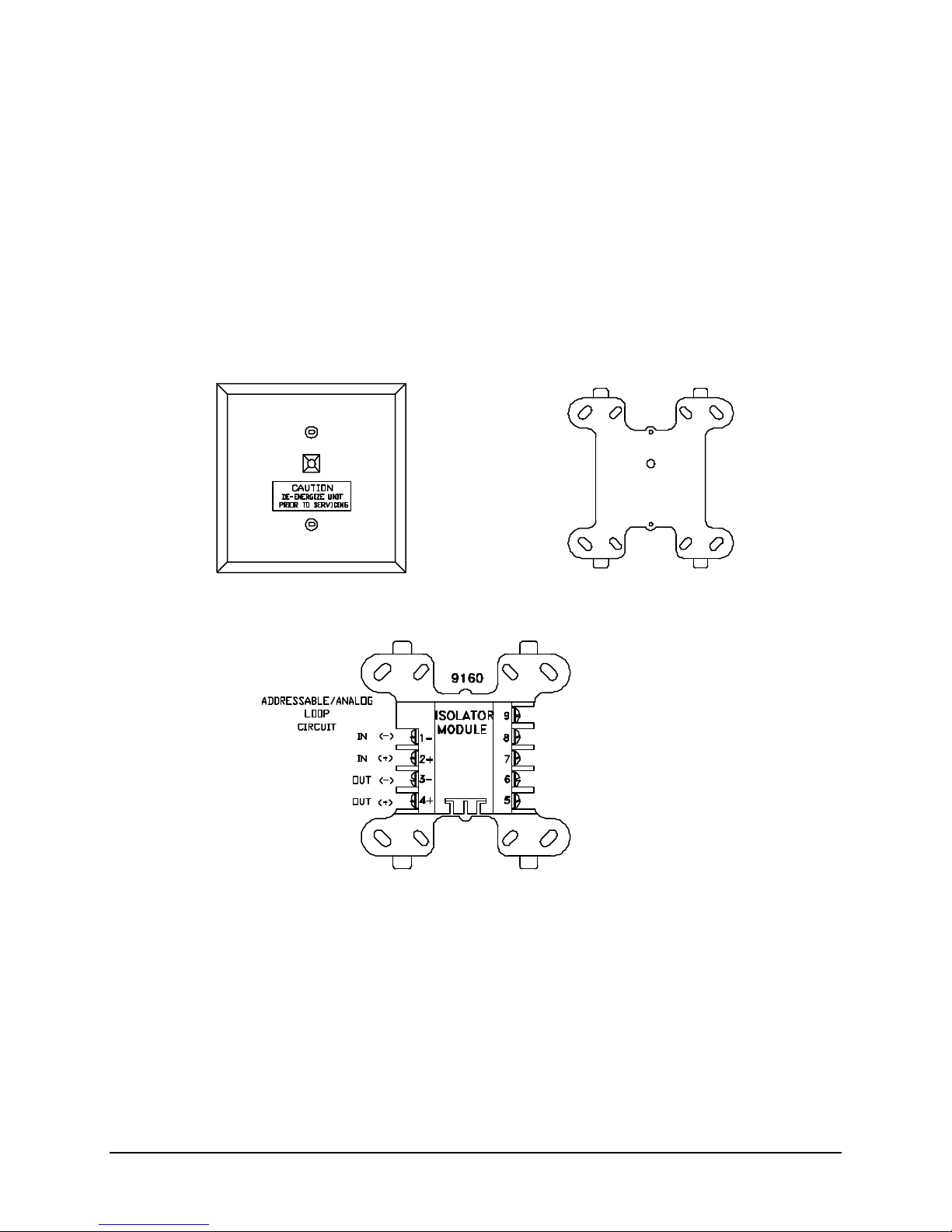
12530/12540 OWNER'S MANUAL
Isolator Module (9160)
The 9180 (System Sensor M500X) addressable device circuit isolator module provides the circuitry to
automatically open and thus "isolate" a branch or section of an addressable device circuit. This isolation
will occur when the 9160 senses a short condition after its position on the circuit. By isolating the shorted
portion of the circuit the control unit will still be able to communicate with and monitor devices not involved
with the faulted section or branch of the addressable device circuit.
During normal operation the red scan/shorted LED will flash several times a minute. In the event that the
monitored portion becomes shorted the red scan/shorted LED will latch on steady and the associated
protected circuit portion will be automatically disconnected from the system and a defined trouble
condition will be reported to the control unit. Once the shorted condition has been removed the 9160
module will automatically unlatch thus restoring normal operations between it, its monitored circuit
portion, and the rest of the system.
P/N 447203 Issue I V-29
Page 69

12530/12540 OWNER'S MANUAL
This page is intentionally blank.
P/N 447203 Issue I V-30
Page 70

12530/12540 OWNER'S MANUAL
VI. PROGRAMMING THE CONTROL UNIT
MAIN TERMINATION BOARD JUMPERS
Factory setting is shown.
P12 – Processor Failure Relay Contact Type
• DGRDO (Open – Form A)
•
• DGRDC (Closed – Form B
P13 – External Power Monitor
• On = Disabled
• Off = Enabled
P50 – Addressable Device Circuit #1 Wiring Style
• Style 4
•
• Style 6/7
P51 – Addressable Device Circuit #2 Wiring Style
• Style 4
•
• Style 6/7
P52 – Reverse Polarity Supervision
• Remote
•
• Local
City Tie Selection Jumper Plug (Move the jumper plug to the desired type of city tie)
JP1 - Reverse Polarity
JP2 – Local Energy
JP3 – Shunt
P/N 447203 Issue I VI-1
Page 71
12530/12540 OWNER'S MANUAL
WJ1 & WJ2 – NAC 3 & 4 External Power Input (cut both jumpers if auxiliary power supply is used)
WJ1
WJ2
MAIN LOGIC BOARD JUMPERS
Factory setting is shown.
P3 – NAC A Degraded Alarm Setting
• DEGRD A
•
• Disable
P4 – NAC B Degraded Alarm Setting
• DEGRD B
•
• Disable
LOOP DRIVER BOARD JUMPERS
Device Type Setting (Factory setting is shown.)
J1 J2 J3 J4 J5
F • • • • •
• • • • •
S • • • • •
NOTE: If the control unit has two Loop Driver Boards, both must be set to the same Device Type Setting.
CONVENTIONAL EXPANSION BOARD JUMPERS
WJ1 & WJ2 – NAC 3 & 4 External Power Input (cut both jumpers if auxiliary power supply is used)
WJ1
WJ2
P/N 447203 Issue I VI-2
Page 72
12530/12540 OWNER'S MANUAL
LOOP/SIGNAL EXPANSION JUMPERS
Factory setting is shown.
P1 – Loop Board
• Not Installed
•
• Installed
P50 – Addressable Device Circuit #3 Wiring Style
• Style 4
•
• Style 6/7
P51 – Addressable Device Circuit #4 Wiring Style
• Style 4
•
• Style 6/7
WJ1 & WJ2 – NAC 1 & 2 External Power Input (cut both jumpers if auxiliary power supply is used)
WJ1
WJ2
WJ3 & WJ4 – NAC 3 & 4 External Power Input (cut both jumpers if auxiliary power supply is used)
WJ3
WJ4
P/N 447203 Issue I VI-3
Page 73
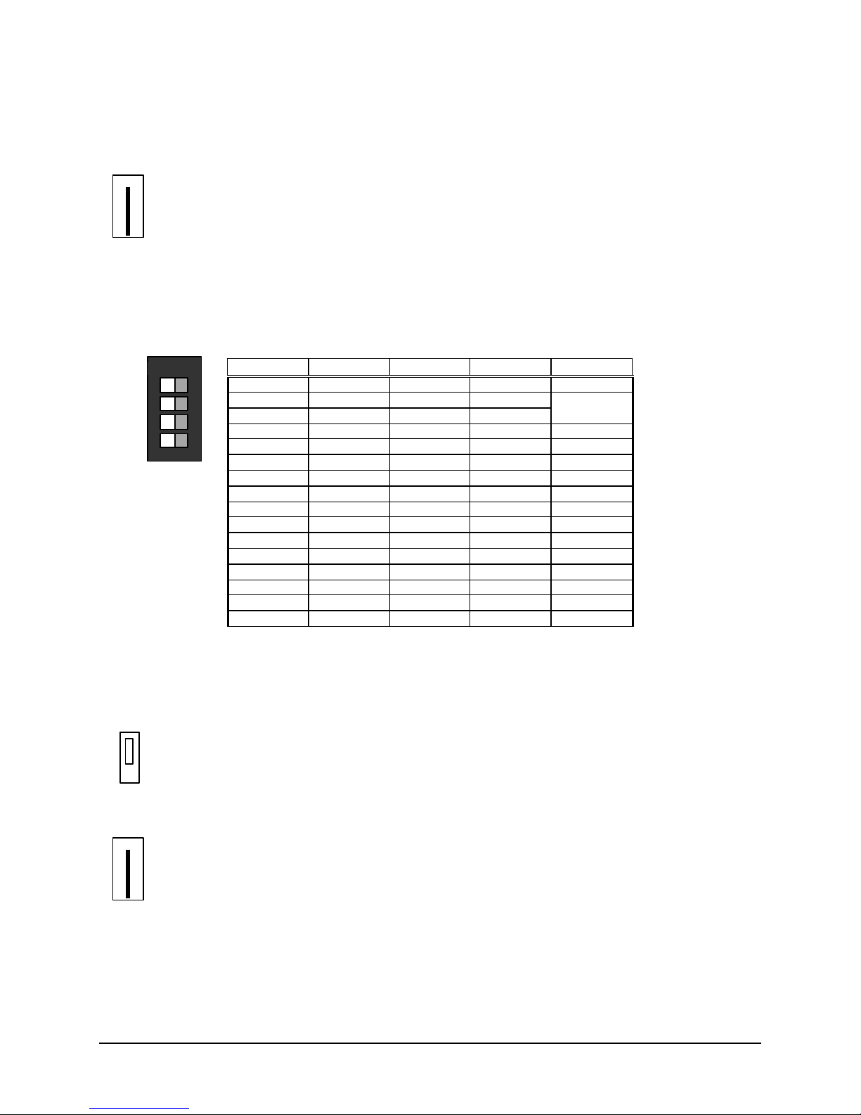
12530/12540 OWNER'S MANUAL
OFF ON
REMOTE LCD ANNUNCIATOR JUMPER
WJ1 – External Power Input (cut jumper if auxiliary power supply is used)
WJ1
REMOTE LCD ANNUNCIATOR SWITCHES
Switches are standard 4-position DIP switches. Slide the switches to the left for Off and to the right for
On. All DIP switches are factory set for off, verify proper settings for proper system operation.
SW1 – Address Selection
Address SW1-1 SW1-2 SW1-3 SW1-4
1 ON ON ON ON
2 OFF ON ON ON
3 ON OFF ON ON
4 OFF OFF ON ON
5 ON ON OFF ON
6 OFF ON OFF ON
7 ON OFF OFF ON
8 OFF OFF OFF ON
9 ON ON ON OFF
10 OFF ON ON OFF
11 ON OFF ON OFF
12 OFF OFF ON OFF
13 ON ON OFF OFF
14 OFF ON OFF OFF
15 ON OFF OFF OFF
16 OFF OFF OFF OFF
SERIAL RELAY UNIT JUMPERS
Factory setting is shown.
P6 – Buzzer Selection (Remote Processor Board)
• Local
•
• Remote
WJ1 – External Power Input (cut jumper if auxiliary power supply is used) (Remote Processor Board)
WJ1
P/N 447203 Issue I VI-4
Page 74
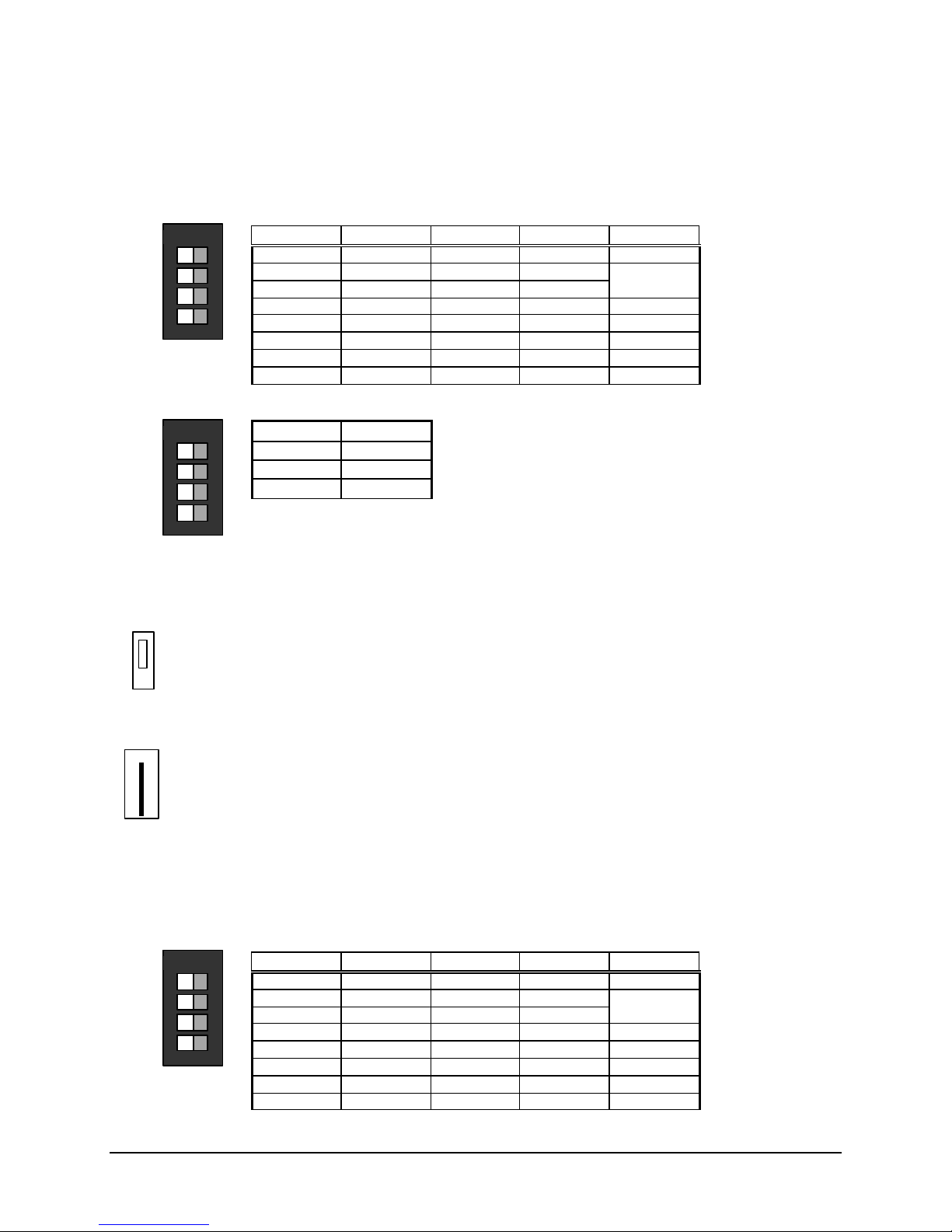
12530/12540 OWNER'S MANUAL
OFF ON
OFF ON
OFF ON
SERIAL RELAY UNIT SWITCHES
Switches are standard 4-position DIP switches. Slide the switches to the left for Off and to the right for
On. All DIP switches are factory set for off, verify proper settings for proper system operation.
SW1 – Address Selection (Remote Processor Board)
Address SW1-1 SW1-2 SW1-3 SW1-4
1 ON ON ON Not used
2 OFF ON ON Not used
3 ON OFF ON Not used
4 OFF OFF ON Not used
5 ON ON OFF Not used
6 OFF ON OFF Not used
7 ON OFF OFF Not used
8 OFF OFF OFF Not used
SW1 – Relay Group Selection (Serial Relay Board)
Note: Only one switch should be activated on each serial relay board.
SW1-1
SW1-2
SW1-3
SW1-4
1-8
9-16
17-24
Not used
SERIAL ANNUNCIATOR UNIT JUMPERS
Factory setting is shown.
P6 – Buzzer Selection (Remote Processor Board)
• Local
•
• Remote
WJ1 – External Power Input (cut jumper if auxiliary power supply is used) (Remote Processor Board)
WJ1
SERIAL ANNUNCIATOR UNIT SWITCHES
Switches are standard 4-position DIP switches. Slide the switches to the left for Off and to the right for
On. All DIP switches are factory set for off, verify proper settings for proper system operation.
SW1 – Address Selection (Remote Processor Board)
Address SW1-1 SW1-2 SW1-3 SW1-4
1 ON ON ON Not used
2 OFF ON ON Not used
3 ON OFF ON Not used
4 OFF OFF ON Not used
5 ON ON OFF Not used
6 OFF ON OFF Not used
7 ON OFF OFF Not used
8 OFF OFF OFF Not used
P/N 447203 Issue I VI-5
Page 75

12530/12540 OWNER'S MANUAL
KEYPAD PROGRAMMING
Customized programming of the 12530/12540 control unit may be accomplished through a keypad
included in the control unit. A sixteen-key, telephone-style keypad mounts on the main logic board within
the cabinet. The keypad may also be easily removed if desired. See the Faraday 447207 Programmer’s
Manual for detailed information of system programming.
PROGRAMMING SECURITY
The following levels of security protect the system from unauthorized use:
• User – Keyswitch
• Maintenance – Keyswitch and 4-digit Maint Password
• Technician – Keyswitch, 5-digit Tech Password and Locked Door
The User and Maintenance Levels are also accessible from the Remote LCD Annunciators.
P/N 447203 Issue I VI-6
Page 76

12530/12540 OWNER'S MANUAL
VII. MAINTENANCE
GENERAL
• Device sensitivity may be read out and alarm thresholds controlled on a per-point basis, as well as
setting overall percent obscuration and day/night variations. Individual points may also be disabled
for service.
To perform these functions on the unit, enter the 4-digit maintenance password into the control unit or
LCD annunciator. When the menu is displayed, select the desired function or sub-function and press the
appropriate operating button. When the function is complete, the menu will provide a command for
exiting the maintenance mode.
Note that any abnormal condition, such as disabled points, will report a
trouble. Confirmation of disabling or re-enabling a point is required to
complete the action, but acknowledgment of the trouble is not required, since
it results from operator action.
Activation of an alarm condition or a time-out after no button activity terminates Maintenance mode.
• The system may automatically scan the operating points and report to a printer, facilitating NFPA 72
test requirements. The control unit may perform this scan once a day, with the time selectable by the
user.
To initiate a non-programmed automatic test cycle, enter the 4-digit maintenance password into the
control unit or LCD annunciator. When the menu is displayed, select Auto-test and press the associated
switch. The Auto-test cycle will be completed and the control unit returns to normal. Results will be
displayed on the display (anomalies only) or the printer (full data) according to the selected mode.
• The system will automatically monitor drift of quiescent sensor output levels and report a
maintenance alert if a preset level is passed, or if a sensor drifts too quickly. This maintenance alert
is annunciated as a trouble.
• The system may be programmed to report the number of times the alarm verify function is initiated by
device, time of day, and/or day of week, allowing location of environmental problems. This datum is
available on the display as described in paragraph 1 above.
• The system may be programmed to alert the operator when scheduled maintenance is required.
• A 2000 event history is maintained, with all events available for chronological review at the operator
level. This history may be cleared only with the Tech Level Code. For details on included data and
use of the history, see operation instructions.
To clear history when data has been read out and restoration of memory space is desired. Activate
maintenance mode as described above and follow menu instructions for clearing the event history.
P/N 447203 Issue I VII-1
Page 77

12530/12540 OWNER'S MANUAL
QUICK TEST
CAUTION: If the control unit has remote connections to the Fire Department or
other monitor, be sure to disable the remote signals and notify the remote
monitoring station before performing test operations, since an off-normal
condition will be indicated.
Quick test is possible in one of two modes, (silent or audible) and is selectable on a per-zone basis. Any
number of zones may be placed into test at the same time, but only one mode of quick test operation is
possible for the whole system at one time. Points not in quick test operate normally. Quick test operation
initiates a system trouble condition.
In the silent mode, all alarm outputs are disabled and only the front panel indications and remote
annunciator LEDs operate. In the audible mode all system sounders will sound momentarily as each or
device is alarmed.
The system maintains a counter of the number of activation’s during the quick test and reports this value
when quick test mode is exited.
Quick test terminates into alarm if more than one device activates simultaneously, or if a device does not
return to normal after being activated within a configurable length of time.
Quick test terminates automatically into normal standby mode using a timer. The value of the timer is
configurable. The timer can be configured to limit the total time of the quick test (i.e. the timer is started
only when quick test is entered), or to limit the time between device activation’s (i.e. the timer is re-started
after each activation).
Alarm activation’s that occur in a system or zone in quick test or by a point in quick test cause the event
to be logged and printed. No other action is taken.
To initiate quick test, enter maintenance mode as described above and follow menu instructions to
configure and initiate the test.
Initiation of General Alarm from the control unit, an RS485 LCD Annunciator, or an RS485 Remote
Processor causes termination of quick test and starts the normal alarm sequence.
Quick test may be terminated by a menu selection or by time-out (set at 5 to 30 minutes) from the last test
activation. Time-out system reactivation is annunciated by a 1/2 second on, 1/2 second off pattern from
system sounders programmed for drill use. A device in alarm condition when quick test is exited causes
the normal alarm sequence.
NOTE: When any problem is observed with the system, refer to the
troubleshooting chart in Appendix C. For any required service, contact a
factory-authorized representative.
P/N 447203 Issue I VII-2
Page 78

12530/12540 OWNER'S MANUAL
VIII. APPENDIX-A: REFERENCE DATA
This appendix provides reference for the following topics:
• Wire selection guides
• Battery size calculations
WIRE SELECTION GUIDES
Resistance of Solid Copper Wire
AWG Ohms per Thousand Feet*
18 8.08
16 5.08
14 3.19
12 2.01
*NEC Chapter 9, Table 8.
Initiating Device Circuit Wire Selection Guide
The following charts are based on the resistance of solid copper wire.
Maximum Wire Loop Distance (feet)
Each 12503 Conventional Expansion Board initiating circuit loop must not have a resistance greater than
100 ohms.
Wire size: 18AWG 16AWG 14AWG 12AWG
Wire length: 12,376 19,685 31,347 49,751
Cable length: 6,188 9,842 15,673 24,875
P/N 447203 Issue I VIII-1
Page 79
12530/12540 OWNER'S MANUAL
Notification Appliance Circuit Wire Selection Guide
Each Notification Appliance Circuit must not have a voltage drop greater than 1 volt. The following chart
is based on the following premises:
• The entire load is at the end of the wire run (worst case).
• Resistance is of solid copper wire
Contact your local distributor or the factory if further information is needed in your circumstances.
Maximum Wire Loop Distance (Feet)
Signal Load (A) 18 AWG 16 AWG 14 AWG 12 AWG
0.1 1,237 1968 3134 4975
0.25 495 787 1253 1990
0.5 247 393 626 995
0.75 165 262 417 663
1.0 123 196 313 497
1.25 99 157 250 398
1.5 82 131 208 331
Addressable Device Circuit Wire Selection Guide
Each addressable device circuit must meet the following requirements:
• Total loop resistance - 40 ohm maximum.
• Total loop capacitance - 0.28uF maximum (56pF/ft. max.)
• Twisted pair wire.
• Unshielded cable.
• Low capacitance cable.
• High velocity of propagation cable - 60% minimum.
• Each loop runs separate from all other circuits.
• Run + out and - out separately from + in and - in.
• Different models or types of cable should not be in the same loop.
Maximum Wire Loop Distance (Feet)
(Includes all branches of a Style 4 loop)
Wire size: 18AWG 16AWG 14AWG * 12AWG
Wire length: 6150 9750 10,000 10,000
Cable length: 3075 4875 5,000 5,000
* The terminal blocks of Faraday addressable devices are rated for a maximum of 14AWG wire.
P/N 447203 Issue I VIII-2
Page 80

12530/12540 OWNER'S MANUAL
BATTERY SIZE CALCULATIONS
Standby Current (A.) Alarm Current (A.)
12530/12540 Control Unit 0.260 0.400
12522 Loop Driver Standby 0.017 0.017 + NA
Board Alarm 0.022 0.022 NA +
12503 Conventional Standby 0.008 X = + NA
Expansion Board Alarm 0.008 X = NA +
12504 Class A Standby 0.000 0.000 NA NA
Adapter Alarm 0.100 X = NA +
12505 Loop/Signal Standby 0.038 0.038 + NA
Expansion Alarm 0.054 0.054 NA +
12506 Remote Standby 0.020 X = + NA
Annunciator Alarm 0.030 X = NA +
12507 Serial Standby 0.010 X = + NA
Relay Unit Alarm 0.170 X = NA +
12508 Serial Standby 0.000 X = + NA
Relay Extender Alarm 0.160 X = NA +
12509 Serial Standby 0.015 X = + NA
Annunciator Unit Alarm (note 4) 0.040 X = NA +
12510 Serial Annun- Standby 0.005 X = + NA
ciator Extender Alarm (note 4) 0.000 X = NA +
12511 Serial Standby 0.038 0.038 + NA
Isolation Board Alarm 0.038 0.038 NA +
12513 DACT Standby 0.038 0.038 + NA
Expansion Module Alarm 0.054 0.054 NA +
12523 Network Standby 0.085 0.085 + NA
Interface Board Alarm 0.085 0.085 NA +
12526 Iso. Network Standby 0.093 0.093 + NA
Interface Board Alarm 0.093 0.093 NA +
12401A Class A Standby 0.002 0.002 + NA
Adapter Alarm 0.030 X = NA +
12402 Alarm Relay Standby 0.000 0.000 NA NA
Board Alarm 0.037 0.037 NA +
15128 Digital Standby 0.070 0.070 + NA
Communicator Alarm 0.180 0.180 NA +
Addressable Devices
Catalog # Quantity X Current (A.)
Standby X = + NA
Alarm X = NA +
Standby X = + NA
Alarm X = NA +
Standby X = + NA
Alarm X = NA +
Standby X = + NA
Alarm X = NA +
Standby X = + NA
Alarm X = NA +
Standby X = + NA
Alarm X = NA +
2-wire Smoke Detectors
Catalog # Quantity X Current (A.)
Standby X = + NA
Alarm X = NA +
Standby X = + NA
Alarm X = NA +
P/N 447203 Issue I VIII-3
Page 81
12530/12540 OWNER'S MANUAL
Standby Current (A.) Alarm Current (A.)
4-wire Smoke Detectors
Catalog # Quantity X Current (A.)
Standby X = + NA
Alarm X = NA +
Standby X = + NA
Alarm X = NA +
End of Line Relay
Catalog # Quantity X Current (A.)
X = + +
X = + +
Notification Appliances
Catalog # Quantity X Current (A.)
X = NA +
X = NA +
X = NA +
X = NA +
Other = + +
TOTAL
Total Standby Current
(from above)
Total Alarm Current
(from above)
A.H. for
Standby
+ = X 1.25 =
Notes:
1. An additional multiplier is included to compensate for the higher discharge rate in alarm. Battery capacity decreases with age.
2. The Standby current + Alarm current must never exceed 4.66 Amps
3. The following states the maximum standby current allowed using a 38 AH battery set:
60 hours of standby time is 0.5 Amps
24 hours of standby time is 1.2 Amps
4. Does not include lamp or LED current, add separately.
A.H. for
Alarm
Hours of Standby Required per
NFPA 72 Standard (4, 24 or 60)
A. x ____ Hours =
5 Minutes of Alarm Operation
A. x 0.33 Hours =
per NFPA 72 Standard*
Calculated
A.H.
De-rating
Factor
A.H. Required
Battery Capacity
AH for Standby
AH for Alarm
P/N 447203 Issue I VIII-4
Page 82
12530/12540 OWNER'S MANUAL
IX. APPENDIX-B: COMPATIBLE DEVICES
DEVICES FOR ADDRESSABLE DEVICE CIRCUITS
Faraday Addressable Modules
Faraday
Cat. No.
8800 Manual Station
8801 Mini- Module for Contact Devices
8802 Module for Contact Devices
8803 Dual Module for Contact Devices
8804 Module for Contact Devices with Relay
8805 Module for Conventional Detectors
8806 NAC Module
Description
Faraday Addressable Detectors
Faraday
Cat. No.
8810 Photo Detector 8853, 8815, 8816, 8840, 8817
8811 Photo/Thermal Detector 8853, 8815, 8816
8812 Thermal Detector, Fixed or Fixed/Rate of Rise 8853, 8815, 8816
Description Compatible Base
Faraday Bases
Faraday
Cat. No.
8853 Base 8810, 8811, 8812
8815 Audible Base 8810, 8811, 8812
8816 Relay Base 8810, 8811, 8812
8840 Duct Housing 8810, 8811
8817 Duct Housing with Relay 8810, 8811
Description Compatible Detector
Faraday Accessories
Faraday
Cat. No.
8809 Isolator Module
8922 Remote LED Annunciator, 4” Octagon Mount ing 8853, 8840
8923 Remote LED Annunciator, Single Gang Mounting 8853, 8840
Notes:
1. Faraday devices, detectors and modules, up to a maximum of 60 devices may be used per
addressable device circuit.
2. For specific wiring and installation information, read the instructions provided with each device.
P/N 447203 Issue I IX-1
Description Compatible Base
Page 83
12530/12540 OWNER'S MANUAL
System Sensor Addressable/Analog Sensors
Faraday
Cat. No.
8406 2251T Photoelectric Sensor w/Thermal - Low
8407 5251P Thermal, Fixed 9155, 9156, 9181, 9297, 9299
8408 5251RP Thermal, Fixed & Rate of Rise 9155, 9156, 9181, 9297, 9299
9152 2551HR Photoelectric Sensor 9155, 9156, 9181, 9297, 9299
9153 2551BT Photoelectric w/Thermal 9155, 9156, 9181, 9297, 9299
9154 5551B Thermal Sensor, Fixed 9155, 9156, 9181, 9297, 9299
9163 1551B Ionization Sensor 9155, 9156, 9181, 9297, 9299
9182 5551R Thermal, Fixed & Rate of Rise 9155, 9156, 9181, 9297, 9299
9187 2251 Photoelectric Sensor - Low profile 9156, 9181, 9189, 9296, 9298
9188 1251 Ionization Sensor - Low profile 9156, 9181, 9189, 9296, 9298
System
Sensor P/N
Description Compatible Base
9156, 9181, 9189, 9296, 9298
profile
System Sensor Bases
Faraday
Cat. No.
9155 B501B Base 8407, 8408, 9152, 9153, 9154, 9163, 9182
9156 B501BH Base w/Horn 8406, 8407, 8408, 9152, 9153, 9154, 9163,
9161 DH500AC/DC Duct Housing with Base With Relay 9152, 9163
9179 DH500 Duct Housing with Base 9152, 9163
9181 B501 Base 8406, 8407, 8408, 9152, 9153, 9154, 9163,
9189 B210LP Base, Low profile 8406, 9187, 9188
9296 B224RB Relay Base, Low profile 8406, 9187, 9188
9297 B524RB Relay Base 8407, 8408, 9152, 9153, 9154, 9163, 9182
9298 B224BI Isolator Base, Low profile 8406, 9187, 9188
9299 B524BI Isolator Base 8407, 8408, 9152, 9153, 9154, 9163, 9182
System
Sensor P/N
Description Compatible Sensor
9182, 9187, 9188
9182, 9187, 9188
System Sensor Addressable/Analog Modules
Faraday
Cat. No.
9157 M500MB Zone Monitor Module
9158 M501M Device Monitor Module
9159 M500CH Control Module
9191 M502M Interface Module
System
Sensor P/N
Description
System Sensor Accessories
Faraday
Cat. No.
9160 M500X Isolator Module
9180 RA400Z Remote LED Annunciator, Single Gang Mounting 9155, 9161, 9179, 9181, 9189
Notes:
1. System Sensor devices, sensors, monitor modules, or control modules, up to a maximum of 99
2. For specific wiring and installation information, read the instructions provided with each device.
System
Description Compatible Base
Sensor P/N
sensors and 99 modules may be used per addressable device circuit.
P/N 447203 Issue I IX-2
Page 84

12530/12540 OWNER'S MANUAL
DEVICES FOR INITIATING DEVICE CIRCUITS
Manual Stations
Faraday
Cat. No.
F1GT 17-450334-35
F1GGT 17-450334-38
F1GHT 17-450334-37
PM3823 XHFA -N4
PM6700 RMS-1P-KL
PM6608 RMS-1T-KL
PM6696 RMS-2T-LP-KL
PM6695 RMS-1T-PS-KL
PM6697 RMS-2T-KO-KL
PM6699 RMS-2T-WP-KL
PM6767 RMS-EX-WP-KL
Mfg.
P/N
Faraday, LLC
Adalet
R.S.G. Inc.
Notes:
3. Any UL Listed contact type non-coded station with compatible contact ratings is acceptable. The
above are listed here for your convenience.
4. For specific wiring and installation information, read the instructions provided with each device.
Waterflow Switches
Faraday
Cat. No.
PM6615 WFD20
PM6616 WFD25
PM6617 WFD30
PM6618 WFD35
PM6619 WFD40
PM6620 WFD50
PM6621 WFD60
PM6622 WFD80
PM6779 EPS10-1
PM6780 EPS10-2
Notes:
1. Any UL Listed contact type waterflow switch with compatible contact ratings is acceptable. The
2. For specific wiring and installation information, read the instructions provided with each device.
Mfg. P/N
System Sensor
above are listed here for your convenience.
P/N 447203 Issue I IX-3
Page 85

12530/12540 OWNER'S MANUAL
Supervisory Switches
Faraday
Cat. No.
PM6623 OSY2
PM6624 PIBV2
PM6781 EPS40-1
PM6782 EPS40-2
Notes:
1. Any UL Listed contact type supervisory switch with compatible contact ratings is acceptable. The
2. For specific wiring and installation information, read the instructions provided with each device.
Mfg.
P/N
System Sensor
above are listed here for your convenience.
Contact Type Heat Detectors
Faraday
Cat. No.
Chemetronics
9341 601
9342 602
9343 603
9344 604
9345 621
9346 622
9347 623
9348 624
9300-136 A-135
9300-190 A-200
9301-136 AT-135
9301-190 AT-200
PM2872-136 EPB501
PM2872-190 EPB502
PM2872-136F EPB503
PM2872-190F EPB504
Notes:
1. Any UL Listed contact type heat detector with compatible contact ratings is acceptable. The
above are listed here for your convenience.
2. For specific wiring and installation information, read the instructions provided with each device.
Mfg. Part
Number
P/N 447203 Issue I IX-4
Page 86

12530/12540 OWNER'S MANUAL
UL Compatible Two-Wire (Circuit Powered) Smoke & Heat Detectors
Zone Identifier – H for 12503 Conventional Expansion Board
Faraday
Detector
w/Base
Air Products & Controls
9267 RW-2W-N 0-30 0.081mA RW-2WN 45681-200
9268 RW-2W-P 0-27 0.110mA RW-2WP 45681-200
Apollo Fire Detectors
9260 w/9262 55000-350 w/45681-220 0-27 0.110mA 55000-350 45681-220
9260 w/9265 55000-350 w/45681-230 0-23 0.130mA 55000-350 45681-230
9261 w/9262 55000-250 w/45681-220 0-30 0.081mA 55000-250 45681-220
9261 w/9265 55000-250 w/45681-230 0-30 0.100mA 55000-250 45681-230
9264 w/9262 55000-153 w/45681-220 0-30 0.057mA 55000-153 45681-220
9264 w/9265 55000-153 w/45681-230 0-30 0.057mA 55000-153 45681-230
9274 w/9262 55000-152 w/45681-220 0-30 0.057mA 55000-152 45681-220
9274 w/9265 55000-152 w/45681-230 0-30 0.089mA 55000-152 45681-230
Faraday, LLC
8842 w/8853 8842 w/8853 0-27 0.110mA 8842 8853
8842 w/8853 (5)
8843 w/8853 8843 w/8853 0-27 0.110mA 8843 8853
8843 w/8853 (5)
8854 w/8853 8854 w/8853 0-27 0.110mA 8854 8853
8854 w/8853 (5)
8854 w/8840 8854 w/8840 0-27 0.110mA 8854 8840
8854 w/8840 (5)
System Sensor
9184 w/9185 1151 w/B110LP 0-25 0.120mA A A
9183 w/9185 2151 w/B110LP 0-25 0.120mA A A
8434 2100S 0-25 0.120mA A --8415 2100TS 0-25 0.120mA A --8423 DH100P 0-25 0.120mA A --9374 1400 0-25 0.120mA A --9375 2400 0-25 0.120mA A --9376 2400TH 0-25 0.120mA A --9358 w/9361 1451 w/B401B 0-25 0.120mA A A
9358 w/9364 1451 w/B401 0-25 0.110mA A A
9359 w/9361 2451 w/B401B 0-25 0.120mA A A
9359 w/9364 2451 w/B401 0-25 0.120mA A A
9360 w/9361 2451TH w/B401B 0-25 0.120mA A A
9360 w/9364 2451TH w/B401 0-25 0.120mA A A
9447 w/9361 5451 w/B401B 0-25 0.120mA A A
9447 w/9364 5451 w/B401 0-25 0.120mA A A
9176 DH400I (1451DH w/DH400) 0-25 0.120mA A A
9177 DH400P (2451 w/DH400) 0-25 0.120mA A A
8842 w/8853 (5)
8843 w/8853 (5)
8854 w/8853 (5)
8854 w/8840 (5)
Notes:
1. These detector models may be mixed and matched as long as the total maximum standby current
does not exceed 3.0 mA per initiating device circuit. The tot al number of detectors on a circuit
should not exceed 30.
2. This control unit is not intended to handle more than one 2-wire detector in alarm, per circuit.
3. The activation of a manual pull station or any other contact device, will prevent any 2-wire
detector on the same circuit from remaining activated or activating.
4. If the smoke detector has an alarm verify function, the circuit must not be programmed for alarm
verify.
5. When these detectors are used with 8844 or 8848 Remote LED, the standby current is doubled.
6. For specific wiring and installation information, read the instructions provided with each device.
Mfg.
Detector
w/Base
Number of
Detectors
Per Circuit
0-13 0.220mA 8842 8853
0-13 0.220mA 8843 8853
0-13 0.220mA 8854 8853
0-13 0.220mA 8854 8840
Maximum
Standby
Current
Detector
Identifier
Base
Identifier
P/N 447203 Issue I IX-5
Page 87

12530/12540 OWNER'S MANUAL
UL Compatible Four-Wire (Separately Powered) Smoke Detectors
Faraday
Detector
w/Base
Air Products & Controls
9269 RW-DC-N 0.081mA 115mA Must use EOL Relay
9270 RW-DC-P 0.110mA 115mA Must use EOL Relay
Apollo Fire Detectors
9221 w/9266 55000-380 w/45681-227 0.205mA 100mA Must use EOL Relay
9222 w/9266 55000-150 w/45681-227 0.086mA 100mA Must use EOL Relay
9259 w/9266 55000-151 w/45681-227 0.086mA 100mA Must use EOL Relay
9260 w/9266 55000-350 w/45681-227
9261 w/9266 55000-250 w/45681-227 0.081mA 100mA Must use EOL Relay
9264 w/9266 55000-153 w/45681-227 0.086mA 100mA Must use EOL Relay
9274 w/9266 55000-152 w/45681-227 0.096mA 100mA Must use EOL Relay
System Sensor
8416 2124S 0.050mA 25mA Must use EOL Relay
8417 2124TS 0.050mA 25mA Must use EOL Relay
8418 2124R 0.050mA 45mA Must use EOL Relay
8419 2124TR 0.050mA 45mA Must use EOL Relay
8420 2124AT 0.050mA 65mA Must use EOL Relay
8421 2124ATR 0.050mA 65mA Must use EOL Relay
8422 2124AITR 0.050mA 65mA Must use EOL Relay
9175 6424 20mA 38.4mA Must use EOL Relay & six wires
9184 w/9186 1151 w/B112LP 0.120mA 36mA Must use EOL Relay
9183 w/9186 2151 w/B112LP 0.120mA 36mA Must use EOL Relay
9338 2124 0.050mA 25mA Must use EOL Relay
9339 2124T 0.050mA 25mA Must use EOL Relay
9340 2124TSRB 15mA 45mA Must use EOL Relay
9358 w/9362 1451 w/B402B 0.120mA 36mA Must use EOL Relay
9359 w/9362 2451 w/B402B 0.120mA 36mA Must use EOL Relay
9360 w/9362 2451TH w/B402B 0.120mA 36mA Must use EOL Relay
Notes:
1. For specific wiring and installation information, read the instructions provided with each device.
2. Each 9273 EOL Relay requires 15 mA. standby current.
Mfg. Detector w/Base Maximum
Standby
Current
0.130mA 100mA Must use EOL Relay
Maximum
Alarm Current
Notes
P/N 447203 Issue I IX-6
Page 88

12530/12540 OWNER'S MANUAL
DEVICES FOR NOTIFICATION APPLIANCE CIRCUITS
Notification Appliances
Faraday
Catalog
Number
446(*1) Bell - Vibrating 21-30 DC 0.110
476(*1) Bell - Vibrating 21-30 DC 0.070
477(*1) Bell - Single Stroke 21-30 DC 0.360
2700-E Strobe Light 20-31 DC 0.059
2700-G Strobe Light 20-31 DC 0.089
2700-J Strobe Light 20-31 DC 0.155
2700-K Strobe Light 20-31 DC 0.164
2700-L Strobe Light 20-31 DC 0.249
2700-M(*2) Sync Strobe Light 20-31 DC 0.059
2700-R(*2) Sync Strobe Light 20-31 DC 0.088
2700-T(*2) Sync Strobe Light 20-31 DC 0.154
2700-Y(*2) Sync Strobe Light 20-31 DC 0.170
2700-Z(*2) Sync Strobe Light 20-31 DC 0.249
2701-E Strobe Light 20-31 DC 0.059
2701-G Strobe Light 20-31 DC 0.089
2701-J Strobe Light 20-31 DC 0.155
2701-K Strobe Light 20-31 DC 0.164
2701-L Strobe Light 20-31 DC 0.249
2701-M(*2) Sync Strobe Light 20-31 DC 0.059
2701-R(*2) Sync Strobe Light 20-31 DC 0.088
2701-T(*2) Sync Strobe Light 20-31 DC 0.154
2701-Y(*2) Sync Strobe Light 20-31 DC 0.170
2701-Z(*2) Sync Strobe Light 20-31 DC 0.249
2705-E Strobe Light 20-31 DC 0.059
2705-L Strobe Light 20-31 DC 0.249
2705-M(*2) Sync Strobe Light 20-31 DC 0.059
2705-Z(*2) Sync Strobe Light 20-31 DC 0.249
2820(*2) Sync Electronic Horn 20-31 DC 0.030
2821(*2) Sync Electronic Horn 20-31 DC 0.030
2824-M(*3) Sync Electronic Horn w/Sync Strobe 20-31 DC 0.030 20-31 DC 0.059
2824-R(*3) Sync Electronic Horn w/Sync Strobe 20-31 DC 0.030 20-31 DC 0.088
2824-T(*3) Sync Electronic Horn w/Sync Strobe 20-31 DC 0.030 20-31 DC 0.154
2824-Y(*3) Sync Electronic Horn w/Sync Strobe 20-31 DC 0.030 20-31 DC 0.170
2824-Z(*3) Sync Electronic Horn w/Sync Strobe 20-31 DC 0.030 20-31 DC 0.249
2880 Electronic Signal-8T 20-31 DC 0.024-0.050 (*4)
2881 Electronic Signal-8T 20-31 DC 0.024-0.050 (*4)
2884-E Electronic Signal-8T w/Strobe 20-31 DC 0.024-0.050 (*4) 20-31 DC 0.059
2884-G Electronic Signal-8T w/Strobe 20-31 DC 0.024-0.050 (*4) 20-31 DC 0.089
2884-J Electronic Signal-8T w/Strobe 20-31 DC 0.024-0.050 (*4) 20-31 DC 0.155
2884-K Electronic Signal-8T w/Strobe 20-31 DC 0.024-0.050 (*4) 20-31 DC 0.164
2884-L Electronic Signal-8T w/Strobe 20-31 DC 0.024-0.050 (*4) 20-31 DC 0.249
2884- M(*2) Electronic Signal-8T w/Sync Strobe 20-31 DC 0.024-0.050 (*4) 20-31 DC 0.059
2884-R(*2) Electronic Signal-8T w/Sync Strobe 20-31 DC 0.024-0.050 (*4) 20-31 DC 0.088
2884-T(*2) Electronic Signal-8T w/Sync Strobe 20-31 DC 0.024-0.050 (*4) 20-31 DC 0.154
2884-Y(*2) Electronic Signal-8T w/Sync Strobe 20-31 DC 0.024-0.050 (*4) 20-31 DC 0.170
2884-Z(*2) Electronic Signal-8T w/Sync Strobe 20-31 DC 0.024-0.050 (*4) 20-31 DC 0.249
5330 Electronic Horn-3T 21-32 DC 0.020-0.025 (*4)
5333 Electronic Horn-3T 21-32 DC 0.020-0.025 (*4)
5334 Electronic Horn-3T 21-32 DC 0.020-0.025 (*4)
5335 Electronic Horn-3T 21-32 DC 0.020-0.025 (*4)
Description Audible
Voltage
(Volts)
Audible
Current
(Amps)
Strobe
Voltage
(Volts)
Strobe
Current
(Amps)
P/N 447203 Issue I IX-7
Page 89

12530/12540 OWNER'S MANUAL
Faraday
Catalog
Number
5340 Electronic Horn 21-32 DC 0.020
5343 Electronic Horn 21-32 DC 0.020
5344 Electronic Horn 21-32 DC 0.020
5345 Electronic Horn 21-32 DC 0.020
5350 Electronic Horn-3T 21-32 DC 0.020-0.025 (*4)
5353 Electronic Horn-3T 21-32 DC 0.020-0.025 (*4)
5354 Electronic Horn-3T 21-32 DC 0.020-0.025 (*4)
5355 Electronic Horn-3T 21-32 DC 0.020-0.025 (*4)
5360 Electronic Horn 21-32 DC 0.020
5363 Electronic Horn 21-32 DC 0.020
5364 Electronic Horn 21-32 DC 0.020
5365 Electronic Horn 21-32 DC 0.020
5370 Electronic Horn-8T 12-32 DC 0.020-0.050 (*4)
5373 Electronic Signal-8T 12-32 DC 0.020-0.050 (*4)
5374 Electronic Signal-8T 12-32 DC 0.020-0.050 (*4)
5375 Electronic Signal-8T 12-32 DC 0.020-0.050 (*4)
5380 Electronic Horn-8T 12-32 DC 0.020-0.050 (*4)
5383 Electronic Signal-8T 12-32 DC 0.020-0.050 (*4)
5384 Electronic Signal-8T 12-32 DC 0.020-0.050 (*4)
5385 Electronic Signal-8T 12-32 DC 0.020-0.050 (*4)
5390 Electronic Chime 21-30 DC 0.020
5394-E Electronic Chime w/Strobe 21-30 DC 0.020 20-31 DC 0.059
5394-G Electronic Chime w/Strobe 21-30 DC 0.020 20-31 DC 0.089
5394-J Electronic Chime w/Strobe 21-30 DC 0.020 20-31 DC 0.155
5394-K Electronic Chime w/Strobe 21-30 DC 0.020 20-31 DC 0.164
5394-L Electronic Chime w/Strobe 21-30 DC 0.020 20-31 DC 0.249
5394- M(*2) Electronic Chime w/Sync Strobe 21-30 DC 0.020 20-31 DC 0.059
5394-R(*2) Electronic Chime w/Sync Strobe 21-30 DC 0.020 20-31 DC 0.088
5394-T(*2) Electronic Chime w/Sync Strobe 21-30 DC 0.020 20-31 DC 0.154
5394-Y(*2) Electronic Chime w/Sync Strobe 21-30 DC 0.020 20-31 DC 0.170
5394-Z(*2) Electronic Chime w/Sync Strobe 21-30 DC 0.020 20-31 DC 0.249
5395 Electronic Chime 21-30 DC 0.020
5398-E Electronic Chime w/Strobe 21-30 DC 0.020 20-31 DC 0.059
5398-G Electronic Chime w/Strobe 21-30 DC 0.020 20-31 DC 0.089
5398-J Electronic Chime w/Strobe 21-30 DC 0.020 20-31 DC 0.155
5398-K Electronic Chime w/Strobe 21-30 DC 0.020 20-31 DC 0.164
5398-L Electronic Chime w/Strobe 21-30 DC 0.020 20-31 DC 0.249
5398- M(*2) Electronic Chime w/Sync Strobe 21-30 DC 0.020 20-31 DC 0.059
5398-R(*2) Electronic Chime w/ Sync Strobe 21-30 DC 0.020 20-31 DC 0.088
5398-T(*2) Electronic Chime w/Sync Strobe 21-30 DC 0.020 20-31 DC 0.154
5398-Y(*2) Electronic Chime w/Sync Strobe 21-30 DC 0.020 20-31 DC 0.170
5398-Z(*2) Electronic Chime w/Sync Strobe 21-30 DC 0.020 20-31 DC 0.249
5405 Sync Control Unit 20-31 DC 0.020
5406 Sync Control Unit 20-31 DC 0.020
6120 Horn 21-30 DC 0.035
6140 Horn 21-30 DC 0.065
6220 Horn 21-30 DC 0.038
6223 Horn 21-30 DC 0.038
6224 Horn 21-30 DC 0.038
6225 Horn 21-30 DC 0.038
6230 Horn 21-30 DC 0.038
6234-E Horn w/Strobe 21-30 DC 0.038 20-31 DC 0.059
6234-G Horn w/Strobe 21-30 DC 0.038 20-31 DC 0.089
6234-J Horn w/Strobe 21-30 DC 0.038 20-31 DC 0.155
6234-K Horn w/Strobe 21-30 DC 0.038 20-31 DC 0.164
6234-L Horn w/Strobe 21-30 DC 0.038 20-31 DC 0.249
Description Audible
Voltage
(Volts)
Audible
Current
(Amps)
Strobe
Voltage
(Volts)
Strobe
Current
(Amps)
P/N 447203 Issue I IX-8
Page 90

12530/12540 OWNER'S MANUAL
Faraday
Catalog
Number
6234-M(*2) Horn w/Sync Strobe 21-30 DC 0.038 20-31 DC 0.059
6234-R(*2) Horn w/Sync Strobe 21-30 DC 0.038 20-31 DC 0.088
6234-T(*2) Horn w/Sync Strobe 21-30 DC 0.038 20-31 DC 0.155
6234-Y(*2) Horn w/Sync Strobe 21-30 DC 0.038 20-31 DC 0.170
6234-Z(*2) Horn w/Sync Strobe 21-30 DC 0.038 20-31 DC 0.249
6235-E Horn w/Strobe-WP 21-30 DC 0.038 20-31 DC 0.059
6235-L Horn w/Strobe-WP 21-30 DC 0.038 20-31 DC 0.249
6235-M(*2) Horn w/Sync Strobe-WP 21-30 DC 0.038 20-31 DC 0.059
6235-Z(*2) Horn w/Sync Strobe-WP 21-30 DC 0.038 20-31 DC 0.249
6238-E Horn w/Strobe 21-30 DC 0.038 20-31 DC 0.059
6238-G Horn w/Strobe 21-30 DC 0.038 20-31 DC 0.089
6238-J Horn w/Strobe 21-30 DC 0.038 20-31 DC 0.155
6238-K Horn w/Strobe 21-30 DC 0.038 20-31 DC 0.164
6238-L Horn w/Strobe 21-30 DC 0.038 20-31 DC 0.249
6238-M(*2) Horn w/Sync Strobe 21-30 DC 0.038 20-31 DC 0.059
6238-R(*2) Horn w/Sync Strobe 21-30 DC 0.038 20-31 DC 0.088
6238-T(*2) Horn w/Sync Strobe 21-30 DC 0.038 20-31 DC 0.155
6238-Y(*2) Horn w/Sync Strobe 21-30 DC 0.038 20-31 DC 0.170
6238-Z(*2) Horn w/Sync Strobe 21-30 DC 0.038 20-31 DC 0.249
6240 Horn 21-30 DC 0.065
6243 Horn 21-30 DC 0.065
6244 Horn 21-30 DC 0.065
6245 Horn 21-30 DC 0.065
6250 Horn 21-30 DC 0.065
6254-E Horn w/Strobe 21-30 DC 0.065 20-31 DC 0.059
6254-G Horn w/Strobe 21-30 DC 0.065 20-31 DC 0.089
6254-J Horn w/Strobe 21-30 DC 0.065 20-31 DC 0.155
6254-K Horn w/Strobe 21-30 DC 0.065 20-31 DC 0.164
6254-L Horn w/Strobe 21-30 DC 0.065 20-31 DC 0.249
6254-M(*2) Horn w/Sync Strobe 21-30 DC 0.065 20-31 DC 0.059
6254-R(*2) Horn w/Sync Strobe 21-30 DC 0.065 20-31 DC 0.088
6254-T(*2) Horn w/Sync Strobe 21-30 DC 0.065 20-31 DC 0.155
6254-Y(*2) Horn w/Sync Strobe 21-30 DC 0.065 20-31 DC 0.170
6254-Z(*2) Horn w/Sync Strobe 21-30 DC 0.065 20-31 DC 0.249
6255-E Horn w/Strobe-WP 21-30 DC 0.065 20-31 DC 0.059
6255-L Horn w/Strobe-WP 21-30 DC 0.065 20-31 DC 0.249
6255-M(*2) Horn w/Sync Strobe-WP 21-30 DC 0.065 20-31 DC 0.059
6255-Z(*2) Horn w/Sync Strobe-WP 21-30 DC 0.065 20-31 DC 0.249
6258-E Horn w/Strobe 21-30 DC 0.065 20-31 DC 0.059
6258-G Horn w/Strobe 21-30 DC 0.065 20-31 DC 0.089
6258-J Horn w/Strobe 21-30 DC 0.065 20-31 DC 0.155
6258-K Horn w/Strobe 21-30 DC 0.065 20-31 DC 0.164
6258-L Horn w/Strobe 21-30 DC 0.065 20-31 DC 0.249
6258-M(*2) Horn w/Sync Strobe 21-30 DC 0.065 20-31 DC 0.059
6258-R(*2) Horn w/Sync Strobe 21-30 DC 0.065 20-31 DC 0.088
6258-T(*2) Horn w/Sync Strobe 21-30 DC 0.065 20-31 DC 0.155
6258-Y(*2) Horn w/Sync Strobe 21-30 DC 0.065 20-31 DC 0.170
6258-Z(*2) Horn w/Sync Strobe 21-30 DC 0.065 20-31 DC 0.249
6300 Mini-Horn 20-31 DC 0.025
6301 Mini-Horn 20-31 DC 0.025
6304-E Mini-Horn w/Strobe 20-31 DC 0.025 20-31 DC 0.059
6304-G Mini-Horn w/Strobe 20-31 DC 0.025 20-31 DC 0.089
6304-J Mini-Horn w/Strobe 20-31 DC 0.025 20-31 DC 0.155
6304-K Mini-Horn w/Strobe 20-31 DC 0.025 20-31 DC 0.164
6304-L Mini-Horn w/Strobe 20-31 DC 0.025 20-31 DC 0.249
6304-M(*2) Mini-Horn w/Sync Strobe 20-31 DC 0.025 20-31 DC 0.059
Description Audible
Voltage
(Volts)
Audible
Current
(Amps)
Strobe
Voltage
(Volts)
Strobe
Current
(Amps)
P/N 447203 Issue I IX-9
Page 91

12530/12540 OWNER'S MANUAL
Faraday
Catalog
Number
6304-R(*2) Mini-Horn w/Sync Strobe 20-31 DC 0.025 20-31 DC 0.088
6304-T(*2) Mini-Horn w/Sync Strobe 20-31 DC 0.025 20-31 DC 0.154
6304-Y(*2) Mini-Horn w/Sync Strobe 20-31 DC 0.025 20-31 DC 0.170
6304-Z(*2) Mini-Horn w/Sync Strobe 20-31 DC 0.025 20-31 DC 0.249
6310 Mini-Horn-S/T 20-31 DC 0.025
6311 Mini-Horn-S/T 20-31 DC 0.025
6314-E Mini-Horn-S/T w/Strobe 20-31 DC 0.025 20-31 DC 0.059
6314-G Mini-Horn-S/T w/Strobe 20-31 DC 0.025 20-31 DC 0.089
6314-J Mini-Horn-S/T w/Strobe 20-31 DC 0.025 20-31 DC 0.155
6314-K Mini-Horn w/Strobe 20-31 DC 0.025 20-31 DC 0.164
6314-L Mini-Horn-S/T w/Strobe 20-31 DC 0.025 20-31 DC 0.249
6314-M(*2) Mini-Horn-S/T w/Sync Strobe 20-31 DC 0.025 20-31 DC 0.059
6314-R(*2) Mini-Horn-S/T w/Sync Strobe 20-31 DC 0.025 20-31 DC 0.088
6314-T(*2) Mini-Horn-S/T w/Sync Strobe 20-31 DC 0.025 20-31 DC 0.154
6314-Y(*2) Mini-Horn-S/T w/Sync Strobe 20-31 DC 0.025 20-31 DC 0.170
6314-Z(*2) Mini-Horn-S/T w/Sync Strobe 20-31 DC 0.025 20-31 DC 0.249
6320(*2) Sync Electronic Horn 20-31 DC 0.030
6321(*2) Sync Electronic Horn 20-31 DC 0.030
6380 Electronic Signal-8T 20-31 DC 0.024-0.050 (*4)
6381 Electronic Signal-8T 20-31 DC 0.024-0.050 (*4)
Description Audible
Voltage
(Volts)
Audible
Current
(Amps)
Strobe
Voltage
(Volts)
Strobe
Current
(Amps)
Key:
(*1) 1=10” gong, 4=4” gong, 5=chime, 6=6” gong, 8=8” gong
(*2) Sync Strobe Light or Sync Electronic Horn require 5405 or 5406 Sync Control Module
(*3) Sync Electronic Horn and Sync Strobe Light require 5405 or 5406 Sync Control Module
(*4) See Installation Instructions for the current of the desired tone.
Cat. No. xxxx-E = Strobe Light (UL1971 15/75cd) Cat. No. xxxx-M = Sync Strobe Light (UL1971 15/75cd)
Cat. No. xxxx-G = Strobe Light (UL1971 30/75cd) Cat. No. xxxx-R = Sync Strobe Light (UL1971 30/75cd)
Cat. No. xxxx-J = Strobe Light (UL1971 60/75cd) Cat. No. xxxx-T = Sync Strobe Light (UL1971 60/75cd)
Cat. No. xxxx-K = Strobe Light (UL1971 75cd) Cat. No. xxxx-Y = Sync Strobe Light (UL1971 75cd)
Cat. No. xxxx-L = Strobe Light (UL1971 110cd) Cat. No. xxxx-Z = Sync Strobe Light (UL1971 110cd)
Accessory Devices
Faraday
Cat. No.
Faraday, LLC
R711-1 711-1 Polarized Auxiliary Relay
MEP-100 15050 Mini-Evac Control Unit
RSE-100 15070 Remote Signal Expander
15222A 15222A Signal Expander Panel
MVP-500 15060 Mini-Voice Control Unit
MVP-501 15061 Mini-Voice Control Unit
Notes:
1. The accessory devices listed above may be wired to activate from the notification appliance
2. For specific wiring and installation information, read the instructions provided with each device.
Mfg. Part Number Description
circuits.
P/N 447203 Issue I IX-10
Page 92

12530/12540 OWNER'S MANUAL
DEVICES FOR AUXILIARY POWER OUTPUTS
The following lists compatible devices for the auxiliary power outputs.
• Door Holders
• Relays
Four Wire (Separately Powered) Heat & Smoke Detectors, See Devices for Initiating Device Circuits.
Door Holders
Faraday
Cat. No.
R.S.G. Inc.
9552 DH-24120FC1 Door Holder
9553 DH-24120SC1 Door Holder
9554 DH-24120GC1 Door Holder
9555 DH-24120GC2 Door Holder
Relays
Faraday
Cat. No.
Faraday, LLC
R711-1 711-1 Remote Relay Unit
Air Products & Contro ls
R712-1 MR-101/C Remote Relay Unit
R712-2 MR-201/C Remote Relay Unit
R712-4 MR-104/C Remote Relay Unit
R712-8 MR-204/C Remote Relay Unit
9273 PAM-4 E.O.L. Relay
System Sensor
PM6849 A77-716B E.O.L. Relay
Notes:
1. The accessory devices listed above may be wired to the auxiliary power outputs.
2. For specific wiring and installation information, read the instructions provided with each device.
Mfg. Part Number Description
Mfg. Part Number Description
P/N 447203 Issue I IX-11
Page 93

12530/12540 OWNER'S MANUAL
This page is intentionally blank.
P/N 447203 Issue I IX-12
Page 94

12530/12540 OWNER'S MANUAL
X. APPENDIX-C: TROUBLESHOOTING
TROUBLESHOOTING INDICATORS
Indicator Location Description
DS1 Main Termination Board City Tie - Indicates open circuit or local energy box needs reset.
DS2 Main Termination Board Monitor - Indicates auxiliary power supply monitor circuit open.
DS3 Main Termination Board Positive Ground - Indicates grounded circuit condition.
DS4 Main Termination Board Negative Ground - Indicates grounded circuit condition.
DS5 Main Termination Board Battery - Indicates open or low battery or blown fuse (F8).
DS7 Main Logic Board Reset - Indicates processor reset in progress.
DEFINITIONS FOR EVENT HISTORY ENTRIES
A. General
ENTRY INDICATES
ALARM General alarm
ALRM Alarm
AVCntr Alarm Verify counter
Blank Plain alarm
CrossZone cross zone point
CZ1A Cross zone
CZ1B Cross zone
CZ2A Cross zone
CZ2B Cross zone
DETECTOR General alarm
HEAT Thermal sensor
ION Ion sensor
LCDxx LCD Annunciator xx
MAIN Main panel
MANL PULL Manual pull station
Mntc Sensor maintenance alert
PAS Positive alarm sequence
PAS INHBT PAS inhibit switch
PHOTO PE sensor
PRE SIGNL pre-signal
PreA Pre-alarm
SUPERVSRY Supervisory
SUPR Supervisory
TRBL Trouble
TROUBLE Trouble
USERx User-defined input x
WATERFLOW Waterflow
P/N 447203 Issue I X-1
Page 95

12530/12540 OWNER'S MANUAL
B. System Troubles
ENTRY INDICATES
AC Trouble AC input low or off
AddrLp l DBLSHT Double short trouble on addressable loop l
AddrLp l OPEN Open circuit trouble on addressable loop l
AddrLp l SHORT Short circuit trouble on addressable loop l
AUX POWER Trb Auxiliary power monitor input trouble
AXLP Bad Msg Main processor to loop processor communication trouble
AXLP Fifo Xmit Main processor to loop processor communication trouble
AXLP NoRespons Main processor to loop processor communication trouble
BATT Trouble Battery input low or off
CITY Trouble Local Energy circuit open
CM1aa NoRespons Programmed control module not responding on loop 1 at address aa
CM1aa DataError More than one device responding on loop 1 at address aa
CM1aa OPEN Control module NAC wiring open on loop 1 at address aa
CM1aa SHORT Control module NAC wiring shorted on loop 1 at address aa
DACT Trouble DACT trouble
DACT Acct Trb DACT account reporting trouble
DACT Com Trouble DACT communication trouble with main processor
DACT PL x Trouble Open or short on DACT phone line x
FLASH FATAL Trb Configuration Flash memory trouble
GRND FAULT Trb Ground Fault trouble
IDCxx Trouble IDC xx wiring is open
LCDxx NoRespons LCD Annunciator xx programmed but is not responding
LCDxx Not Pgmd LCD Annunciator xx is not programmed but is responding
LCDxx Trouble LCD Annunciator xx reports trouble
MD100 Addr=00 Module on loop 1 responded to address 00
MD1aa Not Pgmd Module responding is not programmed on loop 1 address aa
MM1aa NoRespons Programmed monitor module not responding
MM1aa DataError More than one device responding on loop 1 at address aa
MM1aa Bad PWs Module responses are not valid on loop 1 address aa
MM1aa Bad Pgm Module responding is not the type programmed on loop 1 address aa
MM1aa OPEN Module IDC wiring open on loop 1 address aa
MNLP Bad Msg Main processor to loop processor communication trouble
MNLP Fifo Xmit Main processor to loop processor communication trouble
MNLP NoRespons Main processor to loop processor communication trouble
NACxx Trouble NAC xx wiring is open or shorted
PC Pgmr Trb Control unit is not receiving communication from PC
Printer Error Printer is off-line or out of paper
QuickTest Abort Quick Test Timer expired causing abnormal exit of Quick Test
SNl00 Addr=00 Sensor on loop l responded to address 00
SNlaa DataError More than one sensor responding on loop l at address aa
SNlaa NoRespons Programmed sensor not responding on loop l address aa
SNlaa Bad PWs Sensor responses are not valid on loop l address aa
SNlaa Tst Flt Sensor is not entering or exiting test mode on loop l address aa
SNlaa Bad Pgm Sensor responding is not the type programmed on loop l address aa
SNlaa TRBL Sensor needs maintenance on loop l address aa
SNlaa Not Pgmd Sensor responding is not programmed on loop l address aa
SNlaa MaintAlrt Sensor needs cleaning on loop l address aa
SNlaa TestValue Not receiving valid sensor test reading on loop l address aa
Trb Reminder Trouble Reminder timer expired
P/N 447203 Issue I X-2
Page 96

12530/12540 OWNER'S MANUAL
C. System Events
ENTRY INDICATES/NOTES
Alarm Silenced MAIN, LCDxx shown on bottom line
All AV Ctrs Clr All AV counters cleared
AutoProgram Run Auto programming function run
Backup Cnfg Check Backup configuration validated, result on bottom line
Backup Cnfg Edit Backup configuration edited
CMlaa ActvnCnfd Non-relay CM activation confirmed by trouble input on
ConfigsCompared Backup and primary configurations compared, result on bottom line
ConfigsSwapped Backup and Primary configurations swapped
EventHist Clear Event History cleared
Mnt Levl Enter Entered Maintenance level
Mnt Levl Exit Exited Maintenance level
Mnt Levl PW Changed Changed Maintenance level password
MMlaa Disabled MAIN or LCDxx shown on bottom line
MMlaa Enabled MAIN or LCDxx shown on bottom line
NACxx Active Confirm NAC activation confirmed
Panel Reset MAIN, LCDxx shown on bottom line
Power Up
PriConfigCopied Primary configuration copied to backup
QuickTest Exit Exited Quick Test, MAIN or LCDxx shown on bottom line
QuickTest Start Started Quick Test, MAIN or LCDxx shown on bottom line
SNlaa AV CtrClr AV counter for sensor SNlaa cleared
SNlaa AV CtrRll Alarm Verification counter rolled over to 0
SNlaa Disabled MAIN or LCDxx shown on bottom line
SNlaa Enabled MAIN or LCDxx shown on bottom line
System Date Changed Changed system date, old and new dates shown on lines 3 and 4
System Time Changed Changed system time, old and new times shown on lines 3 and 4
Tech Levl Enter Entered Tech level
Tech Levl Exit Exited Tech level
Tech Levl PW Changed Changed Tech level password
User Levl Enter Entered User level
User Levl Exit Exited User level
P/N 447203 Issue I X-3
Page 97

12530/12540 OWNER'S MANUAL
This page is intentionally blank.
P/N 447203 Issue I X-4
Page 98

12530/12540 OWNER'S MANUAL
XI. APPENDIX-D: INSTALLATION
INSTRUCTIONS
This Appendix provides installation instructions for the following option modules and accessories:
• 12522 Loop Driver Board 447202
• 12503 Conventional Expansion Board 446992
• 12504 Class A Adapter 446993
• 12505 Loop/Signal Expansion 446994
• 12506 Remote LCD Annunciator 446983
• 12507 Serial Relay Unit 447073
12508 Serial Relay Extender
• 12509 Serial Annunciator Unit 447074
12510 Serial Annunciator Extender
• 401403 Fire Alarm Accessory Enclosure 447138
• 12511 Serial Isolation Board 447065
• 12513 DACT Expansion Module 447153
• 12401A Class A Adapter 447062
• 12402 Alarm Relay Board 446062
• 12408 Auxiliary Power Supply 446066
• 12410 Digital Communicator Cable 446060
P/N 447203 Issue I XI-1
Page 99

12530/12540 OWNER'S MANUAL
This page is intentionally blank.
P/N 447203 Issue I XI-2
Page 100
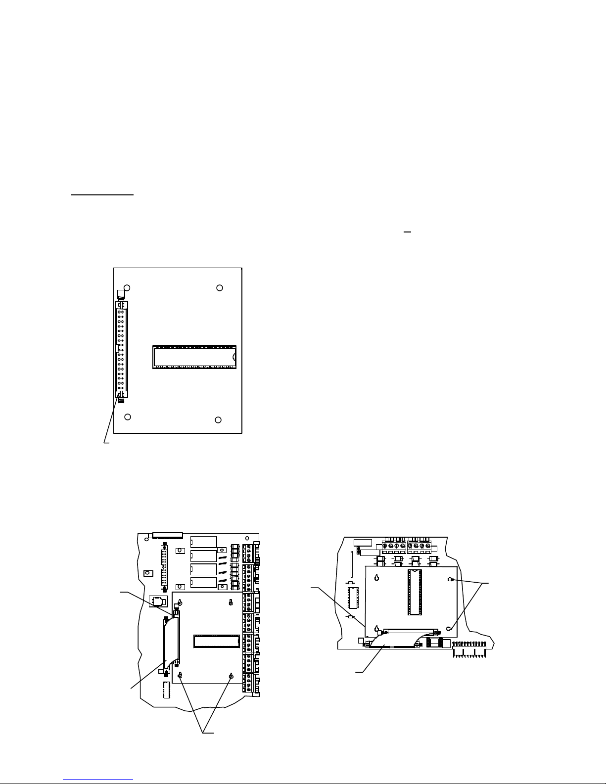
INSTALLATION INSTRUCTIONS AND WIRING FOR
P1
4-
I
O
I
O
P
2
111
1
222
2
ABB
CDD
+
PPP+XX-
1
+X-
LOOP DRIVER BOARD
CAT. NO. LDBF P/N 12522
The 12522 Loop Driver Board is required for the 12530 or 12540 Fire Alarm System Control Unit. It is also
used for the Loop/Signal Expansion Module P/N 12505. This module is an interface between the Main Logic
Board processor and the Faraday addressable devices or System Sensor analog/addressable devices. The
12522 Loop Driver Board sends serial communications and receives data from the addressable devices.
PARTS SUPPLIED
1 12522 Loop Driver Board
4 943165 Spacer, 1”
1 446653 Cable Assembly, 34 pin 3 1/2”
1 447202 Instruction Sheet
12522 WIRING
Cable Assembly
MAIN TERMINATION BOARD MOUNTING
12522 MOUNTING
Step 1.) Installation is to be done by qualified personnel
who have thoroughly read and understood this
instruction sheet.
Step 2.) Disconnect all power into system, including
batteries.
Step 3.) Set jumpers J1-J5 to the “F” position for Faraday
or to “S” for System Sensor addressable
devices.
Step 4.) Mount Loop Driver Board as shown, using four
spacers (P/N 943165) to Main Termination Board
or Expansion Module.
Step 5.) Connect cable assembly (P/N 446653) from the
Main Termination Board connector P7 or 12505
Expansion Board connector P4 to the Loop Driver
Board connector P1.
Step 6.) Connect wires to fire alarm system control unit as
required.
Step 7.) Apply power to system.
Step 8.) Check for proper operation of functions.
NOTE: See the 12530/12540 Owner's Manual (P/N
447203) for compatible devices and proper field
wiring.
LOOP/SIGNAL EXPANSION BOARD MOUNTING
Loop Board
Cable Assembly
FARADAY, LLC
447202 ISSUE I PAGE 1 OF 1
Spacers (4)
NA
NA
NA
NA
Loop Board
-
OU
OU
OU
I
OU
I
TB9
Cable Assembly
LOOP
INSTALLED
P4
4
3- 3
3
TB
4-
3-
4
TB
Spacers (4)
STYLE4
LOOP 4
STYLE6
 Loading...