

Page 1
Installation/Wiring Instructions
Photoelectric Detector Models 8854/8843
These instructions are written in accordance with the installation guidelines of NFPA No. 72, National Fire Alarm Code,
and CAN/ULC-S524, The Installation of Fire Alarm Systems.
DETECTOR PLACEMENT
For a clear air, 0 to 4000 ft/min velocity application, use 30
foot center spacing (900 sq ft) from NFPA Standard 72 Chapter 5 and CAN/ULC-S524 as a starting point for a detector
installation layout. This spacing, however, is based on ideal
conditions – smooth ceiling, no air movement, and no physical obstructions. In some applications, considerably less area
is protected adequately by each smoke detector. In all installations, place the detector on the ceiling, a minimum of
6 inches from a side wall, or on a wall, 6 inches from the
ceiling.
Follow the drawings provided or approved by Faraday or by
its authorized distributors.
See NFPA 72, NATIONAL FIRE
ALARM CODE, Chapter 5 for additional guidance on special
issues such as beamed construction and high stockpiling.
TO AVOID NUISANCE ALARMS:
DO NOT locate the 8854/8843 detector where excessive smoke
concentrations exist under normal conditions, or in areas of prolonged high relative humidity where condensation occurs.
DO NOT locate the 8854/8843 detector next to an oil burner,
kitchen, or garage where exhaust fumes can trigger an alarm.
Other causes of false alarms are dust accumulation, heavy
concentrations of steam, heavy pipe or cigar smoke, and
certain aerosol sprays.
AIR CURRENTS
Before a detector can sense a fire, the products of combustion
or smoke must travel from the fire to the detector. Since their
travel is especially influenced by air currents, consider the
movement of air in the design of the system.
While combustion products tend to rise, drafts from hallways,
air diffusers, fans, etc., may help or hinder the travel of combustion products to the detector. When positioning a detector
at a particular location, give consideration to windows and
doors, both open and closed, and to influencing air movement.
Never install a detector in the air stream of a room air supply
diffuser. It is better to position a detector closer to an air return.
SPECIFICATIONS
Environmental
Temperature: 32OF (0OC) to 100OF (38OC).
Humidity: Up to 93% RH, non condensing
Air Pressure: No effect.
Thermal Alarm Temp.: 135
0
F (570C)
Electrical
Voltage: 16-27 VDC
Ripple: 3V peak-to-peak
Supervisory Current: 110µA max
Alarm Current: 17-24mA
Start-up Time: 50 seconds max
DETECTOR WIRING
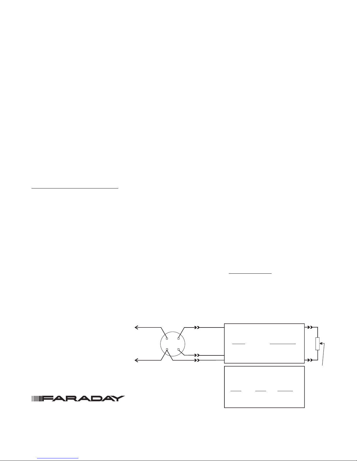
The 8854/8843 should be connected as shown in Figure 1
using the separate mounting base, Model 8853. Follow the
control panel wiring connection drawing installed on the inside face of each control panel cover. See 8853 instruction,
P/N 315-094193FA, for base mounting. Duplicate wiring information is also in the Installation, Operation, and Maintenance Manual provided with every control panel. Note any
limitations on the number of detectors and restrictions
on the use of remote devices permitted for each circuit.
INSTALLATION / REMOVAL OF DETECTOR
TO INSTALL:
• Align LED in detector with LED symbol on base and insert detector into base.
• Rotate detector
on it until the detector drops fully into base.
• Then rotate the detector clockwise until it stops and locks
in place. Insert optional locking screw (Order
P/N 446371).
counterclockwise while gently pressing
Figure 1
Installation and Wiring Diagram for
8854/8843 Conventional Detector
Siemens Building Technologies, Inc.
8 Fernwood Road • Florham Park, NJ 07932
Tel: (973) 593-2600 • Fax: (973) 593-6670
Web: www.faradayfirealarms.com
P/N 315-094198FA-7
8853
[NO REMOTE DEVICE]
+
TO INITIATING
CIRCUIT OF
SIEMENS
BUILDING TECHNOLOGIES, INC.
CONTROL PANEL
(SEE CAUTION 1)
-
CAUTION:
1. Do not use looped wire under base terminal 5.
Break wire run to provide supervision of connection.
2. When a remote relay is used to control a critical
system function, the relay and its associated
detector and optional module(s) must be the
ONLY devices on the initiating circuit.
1a
1b
5
6
1b
6
5
[WITH REMOTE DEVICE(S)]
SEE REMOTE DEVICE INSTRUCTIONS
FOR WIRING DETAILS:
DEVICE
8852
8845, 8849
8844, 8848
MULTIPLE REMOTE DEVICES
If remote devices are supported by the initiating circuit,
each detector/base may have up to 2 remote devices
with the following configurations and restrictions only:
Remote
Device 1
8852
8852
8845, 8849
8845, 8849
8853
Remote
Device 2
8845, 8849
8844, 8848
8844, 8848
8845, 8849
INSTALLATION
INSTRUCTIONS
P/N 315-095519FA
P/N 315-094925FA
P/N 315-094926FA
Restrictions
See Caution 2
See Caution 2
Wire from base to
8844 / 8848
to
8852
1b
5
END OF
DEVICE
(NOTE
POLARITY
WHEN
APPLICABLE)
+
-
LINE
Page 2
TO REMOVE:
• Loosen locking screw, if installed. Then rotate the detector counter clockwise until stop is reached.
• Pull detector out of base.
LED INDICATOR OPERATION
The 8854/8843 contains an LED indicator capable of flashing in either one of three distinct colors: green, yellow, or
red. Every seven seconds, the microprocessor based detector checks the following:
• for smoke in its sensing chamber
• that its smoke sensitivity is within the range indicated on
the nameplate label
• that its critical smoke sensing electronics are operating.
Based on the results of these checks, the LED indicator
flashes as follows:
Flash
Color Condition
Green
Yellow
Red Alarm On steady
No
Flashes
Normal supervisory operation.
Smoke sensitivity is within rated
limits.
Detector requires service
(cleaning or repair) or is
operating beyond its
environmental specifications.
Detector is not powered, or
requires repair.
Interval
(Seconds)
7
7-30
-
TESTING AND MAINTENANCE
To assure proper operation of the detector and control panel,
it is required that both the Sensitivity test and the Functional
test be conducted.
SENSITIVITY TEST
The 8854/8843 monitors its smoke sensitivity automatically
and requires no test equipment. A green flash of the detector LED about every seven seconds indicates that the smoke
sensitivity is within its listed limits.
FUNCTIONAL TEST
To test the detector and control panel for functional operation, use Faraday Test Gas, P/N 8919. Follow the instructions on the gas canister label.
CLEANING PROCEDURE
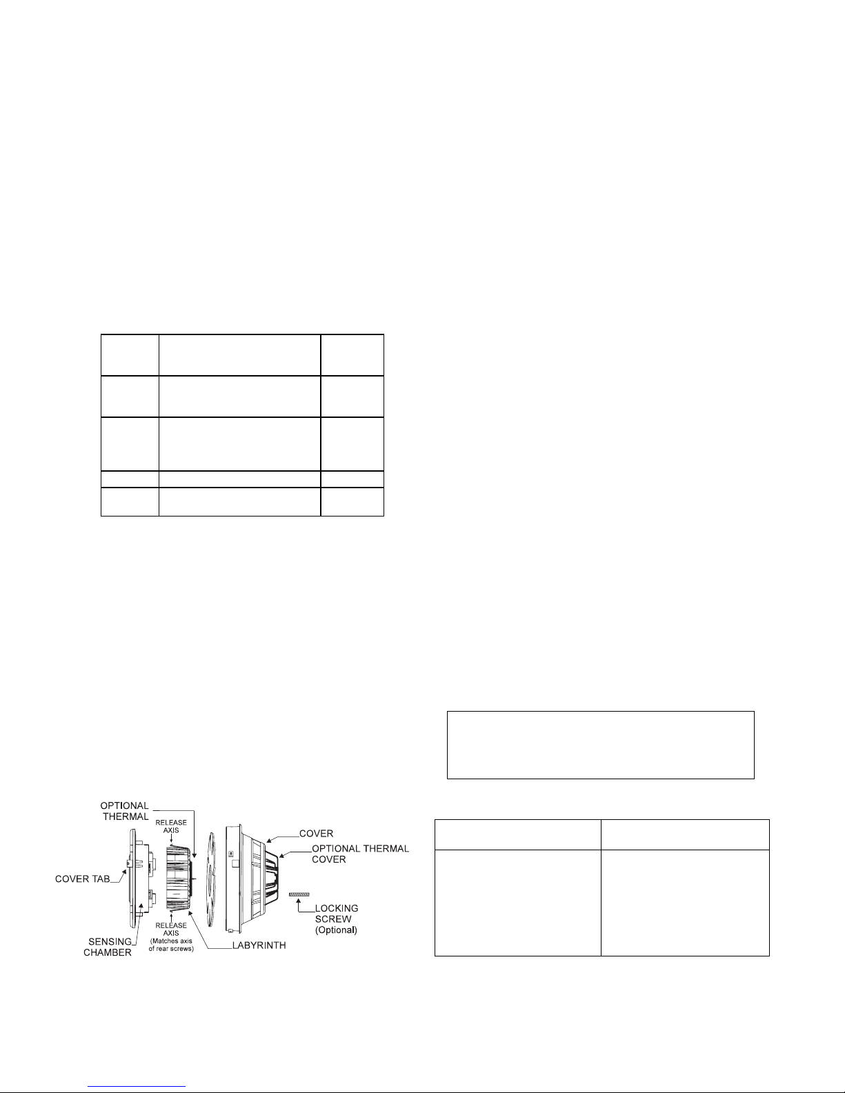
(See Figure 2)
1. Notify the proper personnel that the fire alarm system is
being serviced.
2. Remove the detector to be cleaned from its base. (See
removal section.)
3. Using a small blade screwdriver, remove the cover from
the rest of the detector by releasing the 2 cover tabs located on the outside of the cover. Separate the foam
screen from the cover.
4. 8854: Remove the labyrinth from the sensing chamber
by squeezing the labyrinth sides along the release axis
and pulling out.
8843: Carefully remove the labyrinth/thermal holder assembly being sure not to damage or disconnect the thermal wires.
5. Clean dust from the detector cover, foam screen, sensing chamber and labyrinth using a brush, or by blowing
with compressed air.
CAUTION: Do not use a compressed air supply that may
contain an oil residue.
WARNING: Do not remove or loosen the two screws on
the rear of the detector, or calibration will be
lost.
NOTE: The insect screen and labyrinth may be replaced
with new parts, rather than be cleaned. Contact
Faraday’s Product Service to order Detector Maintenance Kit, Model 8850.
NOTE: Do not disconnect the thermal wires from the de-
tector.
6. Reassemble the detector by reversing the steps used
for disassembly, and reinstall in its base.
7. Test the detector. (See Detector Testing section of this
instruction.) Reset the control panel zone after each
alarm.
NOTE: After applying or momentarily interrupting power to
the detector, it is normal for it to take as long as 50
seconds for the LED to begin flashing to indicate
its operating status.
8. When all service has been completed, notify personnel (See Step 1) that system service has been completed.
CAUTION
NO FIELD REPAIRS OF THE DETECTORS
SHOULD BE ATTEMPTED. THE DETECTORS
ARE FACTORY REPAIRABLE ONLY.
Figure 2 Disassembling of Photochamber
P/N 315-094198FA-7
COMPATIBLE CONTROL EQUIPMENT
Equipment Installation/Wiring
Compatibility Identifier Instructions
* CIDI-DD/DB (LW-500) P/N 315-079626FA-9
LW-450 P/N 315-094131FA-2
* LW-400 P/N 315-092538FA-10
* LWZE-4 (LW-400) P/N 315-092430FA-4
LW-401 P/N 315-095997FA-3
LWZE-4A (LW-401) P/N 315-096018FA-3
LWZE-8A (LW-401) P/N 315-096022FA-3
The detector model number is the compatibility identifier.
*Control equipment does not support remote accessories; e.g.
lamps or relays.
 Loading...