

Page 1
Air Duct Monitoring Housings
Installat ion Instructions
Models 8741, 8742 and 8743
P/N 315-049708FA-4
INTRODUCTION Models 8741, 8742 and 8743 are air duct monitoring hous-
ings containing sampling tubes. When used with a compatible smoke detector, smoke and combustion products are
detected for shutdown of the duct system and/or operation
of supplementary equipment as provided by the system
control panel. See the following chart for usage.
ledoMsrotceteDelbitapmoCyaleR
14784588
,
0178
,
3178oN
24784588seY
34780178
,
3178seY
FF
FF
F
oror
oror
or
compat compat
compat compat
compat
ible control equipment,ible control equipment,
ible control equipment,ible control equipment,
ible control equipment,
see c see c
see c see c
see c
harhar
harhar
har
ts on the pagets on the page
ts on the pagets on the page
ts on the page
11
11
1
2 of this manual.2 of this manual.
2 of this manual.2 of this manual.
2 of this manual.
TECHNICAL DATA AIR DUCT CONDITIONS
Temperature Range:
32
O
F (0OC) - 100OF (38OC) per UL 268/268A
Altitude Range:
8741, 8742 and 8743 — No altitude limitations
Relative Humidity Range:
10-85% (non-condensing/non-freezing)
Air Duct Velocity Range:
100-4000 ft/min – 8741, 8742 and 8743
Sampling Tube Pressure Range of Differences:
Greater than 0.01 and less than 1.2 inches of water column
These air duct detectors are designed for detection and
control of products of combustion in a duct system.
TheyThey
TheyThey
They
are not to be used forare not to be used for
are not to be used forare not to be used for
are not to be used for
open area prot open area prot
open area prot open area prot
open area prot
ectect
ectect
ect
ion.ion.
ion.ion.
ion.
DO NOT USE air duct detectors with Alarm Verification.
Page 2

P/N 315-049708FA-42
APPLICATION The 8741, 8742 and 8743 duct smoke detectors provide early
detection of smoke and products of combustion present in
air moving through an HVAC duct supply, return, or both.
These devices are designed to prevent the recirculation of
smoke in areas by the air handling system’s fans and blowers. Complete systems may be shut down in the event of
smoke detection.
For the correct installation of a duct smoke unit please refer
to NFPA 72 (National Fire Alarm Code), NFPA 90A (Standard
for Installation of Air Conditioning and Ventilation Systems),
NFPA 70 (National Electrical Code) and NFPA 92A (Recommended Practice for Smoke Control Systems).
OPERATION When the Models 8741, 8742 and 8743 are operating, a
sample of air is drawn from the duct and passed through the
sampling chamber by means of the input sampling tube. The
air sample passes through the smoke detector mounted in
the duct housing and is exhausted back into the duct
through the outlet tube.
This detector is equipped with cover removal switch (SW1) that
instantly provides a trouble condition upon removal of the clear
cover. For all testing and inspection with the cover removed, the
cover removal switch (designated as SW1 on PCB) must be
manually depressed to simulate normal operation.
LED Indicator The 8741, 8742 and 8743 contain an LED indicator (located on
the smoke detector) capable of flashing either one of three
distinct colors: green, yellow, or red. During each flash interval,
the microprocessor based detector checks the following:
• for smoke in its sensing chamber
• that its critical smoke sensing electronics are operating.
Based on the results of these checks, the LED indicator
flashes as follows:
)sdnoceS(lavretnIhsalF
hsalF
roloCnoitidnoC45880178/3178
neerG.noitarepoyrosivrepuslamroN74
wolleY
siro)riaperro
gninaelc(ecivresseriuqerrotceteD
.snoitacificepslatnemnorivnestidnoyebgnitarepo
03-74
deRmralA½24
sehsalFoN.ri
aperseriuqerro,derewoptonsirotceteD--
Page 3
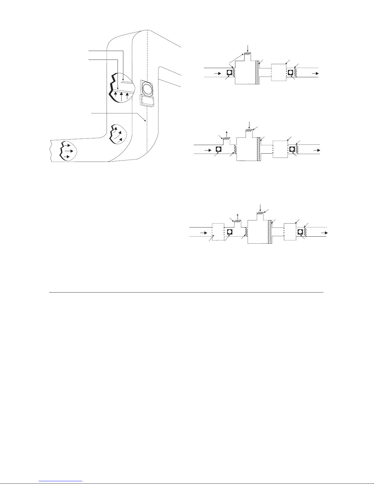
3 P/N 315-049708FA-4
Figure 2
Recommended Locations in Duct Systems
RETURN
AIR
SUPPLY
AIR
AIR DUCT
HOUSING
AIR DUCT
HOUSING
DAMPER
BLOWER
FILTER
PLENUM
FRESH AIR INTAKE
DAMPER
TYPE A: CLOSED SYSTEM - NO EXHAUST
D D
TYPE B: PROVISION FOR EXHAUSTING
SOME PERCENTAGE OF RETURN AIR
RETURN
AIR
SUPPLY
AIR
AIR DUCT
HOUSING
AIR DUCT
HOUSING
DAMPER
DAMPER
BLOWER
FILTER
PLENUM
FRESH AIR INTAKE
DAMPER
D D
EXHAUST AIR
OUTPUT
DAMPER
TYPE C: RETURN AIR UNDER POSITIVE PRESSURE
FROM SEPARATE BLOWER
EXHAUST AIR
OUTPUT
DAMPER
RETURN
AIR
SUPPLY
AIR
AIR DUCT
HOUSING
RETURN AIR
BLOWER
AIR DUCT
HOUSING
DAMPER
DAMPER
BLOWER
FILTER
PLENUM
FRESH AIR INTAKE
DAMPER
D D
Figure 1
Typical Mounting of Duct Housing
OUTLET
TUBE
INPUT
SAMPLING
TUBE
CENTER
LINE
OF DUCT
C
L
MOUNTING THE AIR DUCT HOUSING
Location on Duct System
This guideline contains general information on duct smoke
detector installation, but does not preclude the NFPA
documents listed. Siemens Industry, Inc. assumes no
responsibility for improperly installed duct detectors. To
determine the correct installation position for an 8741, 8742
or 8743 duct smoke detector, the following factors must be
considered.
1) A uniform non-turbulent (laminar) airflow between 100 ft/
min. to 4,000 ft/min. must be present in the HVAC duct.
To determine duct velocities, examine the engineering
specifications that define the expected velocities or use
an Alnor model 6000AP velocity meter (or equivalent).
Page 4

P/N 315-049708FA-44
2) To minimize the impact of air turbulence and stratification
on performance, a duct smoke detector should be
located as far as possible downstream from any obstruction (i.e. deflector plates, elbows, dampers, etc.). In all
situations, confirmation of velocity and pressure differential within specifications is required.
The pressure differential between the input sampling
(high pressure) tube and outlet (low pressure) tube for
the 8741, 8742 or 8743 duct smoke detector should be
greater than 0.01 inches of water and less than 1.2
inches of water.
3) Identify a code compliant location (supply or return side,
or both) for the installation of the duct unit that will
permit easy access for viewing and serviceability.
4) When installing on the return side, install duct units prior
to the air being exhausted from the building or diluted
with outside “fresh” air.
5) When installing duct smoke units downstream of filters,
fires occurring in the filters will be detected, but if the
filters become blocked, insufficient air flow through the
duct unit will prevent the correct operation of the duct
detector. Duct units installed in the supply air side may
monitor upstream equipment and/or filters.
6) Where possible, install duct detectors upstream of air
humidifiers and downstream of dehumidifiers.
7) To prevent false alarms, the duct detector should not be
mounted in areas of extreme high or low temperatures,
in areas where high humidity exists, or in areas where
the duct may contain gases or excessive dust.
Duct Preparation The 8741, 8742 and 8743 Housings come with an installation
kit that contains the following items:
• Short return (outlet) sampling tube
• Stopper
• Two #12 x
3
/4” sheet metal screws
• Mounting template (packaged separately)
Remove mounting template from the installation kit. Remove
paper backing from the mounting template and affix it to the
duct at the desired location. Using the template as a guide,
drill (2) mounting holes, 3/32" (2.5mm) for the #12 X
3
/4”
sheet metal screws packaged in the installation kit. Drill or
Page 5
5 P/N 315-049708FA-4
punch (2) 1¼” (32mm) holes for input sampling and outlet
tubes, using the template as a guide. Clean all holes.
Sampling Tube Installation
The 8741, 8742 and 8743 duct smoke detectors use a
specially notched sampling tube, which may be ordered
separately in one of four standard lengths.
ST-10 For duct widths of 6" to 1.0’
ST-25 For duct widths of 1.0’ to 3.0’
ST-50 For duct widths of 3.0’ to 5.0’ (requires support)
ST-100* For duct widths of 5.0’ to 10.0’ (requires support)
*
This model is supplied as two 5 ft. sections with a coupling.
Assembly is required for installation.
Each model is manufactured with a different number and
size of sampling holes. Only the specific tube must be used
for the specified duct width.
Standard sampling tubes are steel tubes with air intake holes
drilled the entire length of the tube. These tubes can be cut
to length and must span at least 80% the width of the duct.
Sampling tubes over 3.0’ must be supported on the opposite
side of the duct. To ensure the correct operation, the red
stopper (stopper in installation kit) must be inserted in the
end of the air input sampling tube. If the input tube protrudes
through the opposite side of the duct, the opening around
the tube must be sealed. For custom duct widths, always
use the next longest standard size and cut down to the exact
requirement.
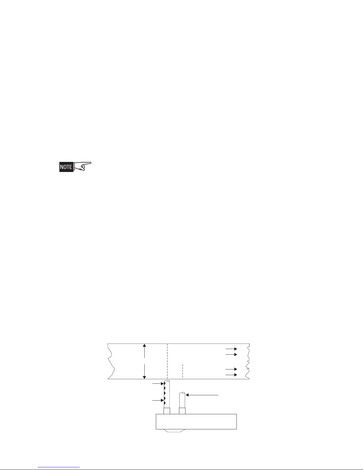
Once the airflow direction has been determined (refer to Figure
3), insert the input and outlet tubes into the duct housing.
INPUT
TUBE HOLES
FACE AIR FLOW
INSERT RED STOPPER
THIS END OF INPUT
TUBE
OUTLET
TUBE INSTALLED
DOWNSTREAM OF AIRFLOW
DO NOT INSERT RED STOPPER
AIR FLOW DIRECTION
DUCT WIDTH
TUBE SUPPORT ONLY FOR DUCTS GREATER THAN 3 FEET WIDE
NOTE: Mountings shown
are typical. Detectors can
be installed side, bottom
or top of duct as long as
proper tube operation and
flow/pressure performance
is maintained.
Figure 3
Sampling Tube Orientation
Page 6

P/N 315-049708FA-46
1. Remove the cover from the housing.
2. Loosen the screw and rotate the tube retainer until the
input tube is inserted and oriented properly. Ensure that
the notched end of the tube is inside the housing and
that the air input sampling tube is positioned so that the
input holes are directly facing the airflow.
3. Once the tube is installed, rotate the retainer back into
place and tighten screw.
4. Install the outlet tube in the remaining position. Once
the tube is installed, rotate the retainer back into place
and tighten screw.
Mounting After securing the input and outlet tubes to the duct smoke
unit, (or initially placing the tubes through the 1¼” holes
drilled or punched in the HVAC duct to accept the input and
outlet tubes and then attaching them to the duct unit), hold
the duct unit assembly in position and use (2) # 12 X
3
/4”
sheet metal screws (packaged in the installation kit) to secure
the duct smoke detector to the HVAC duct sheet metal.
Air Duct Sampling Tube Pressure Measurement
The Model 8883 Pressure Differential Measuring device
should be used to ensure that the sampling tube pressure
differential is within the specified limits. The differential
pressure between the two tubes should be greater than 0.01
inches of water and less than 1.2 inches of water. Qualified
personnel should take measurements in accordance with
the 8883 instructions, P/N 315-085535FA.
WIRING
Conduit Knockouts To remove plastic knockout, first cut the plastic tab on the
specific knockout. Refer to Figure 4 to locate the tab. Then,
using a screw driver placed at the tab location, tap with a
hammer until the knockout breaks out. Clean the hole before
installing conduit.
PLASTIC TAB
KNOCKOUT
SIDE REAR OF AIR DUCT HOUSING
KNOCKOUT FACTORY
REMOVED
Figure 4
Removing the Knockouts
Page 7

7 P/N 315-049708FA-4
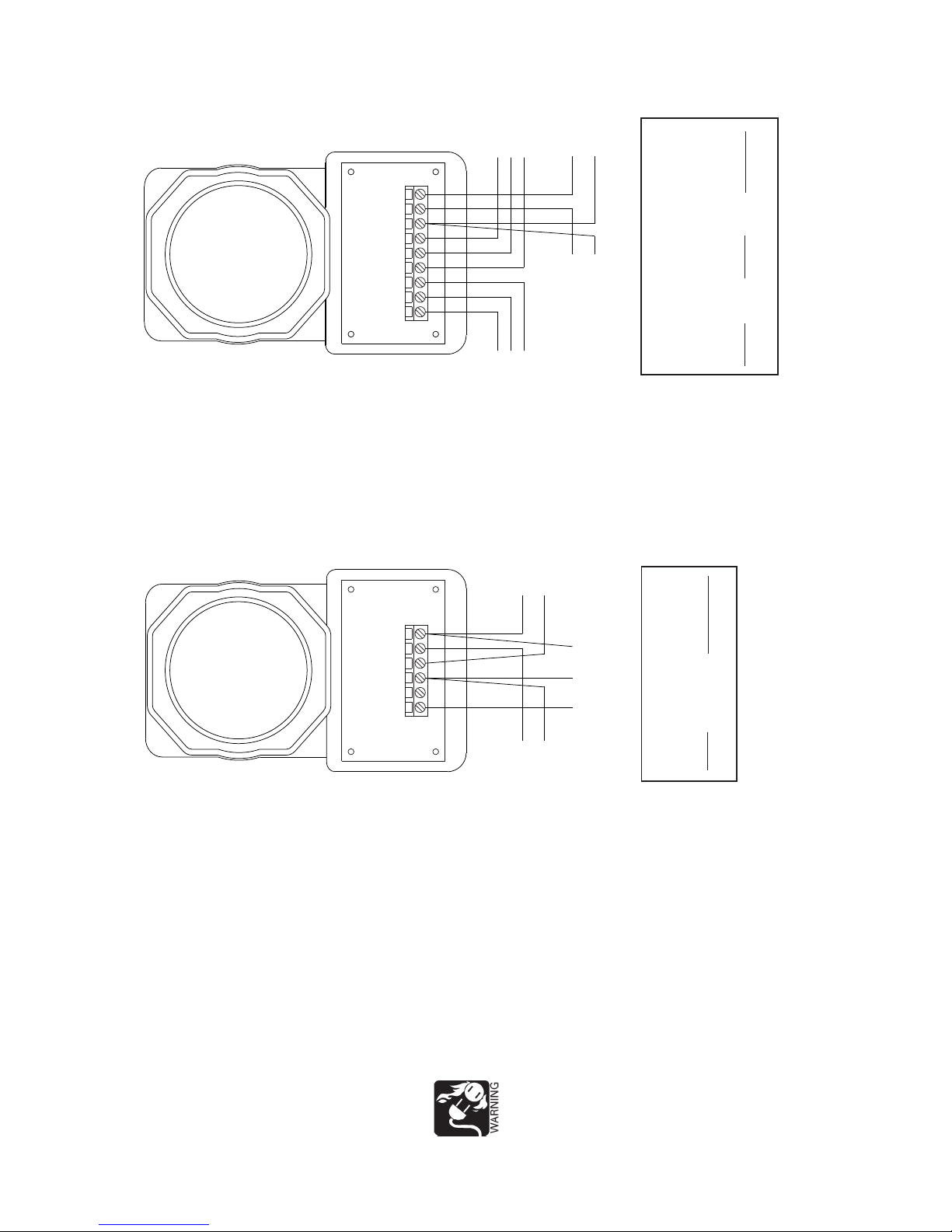
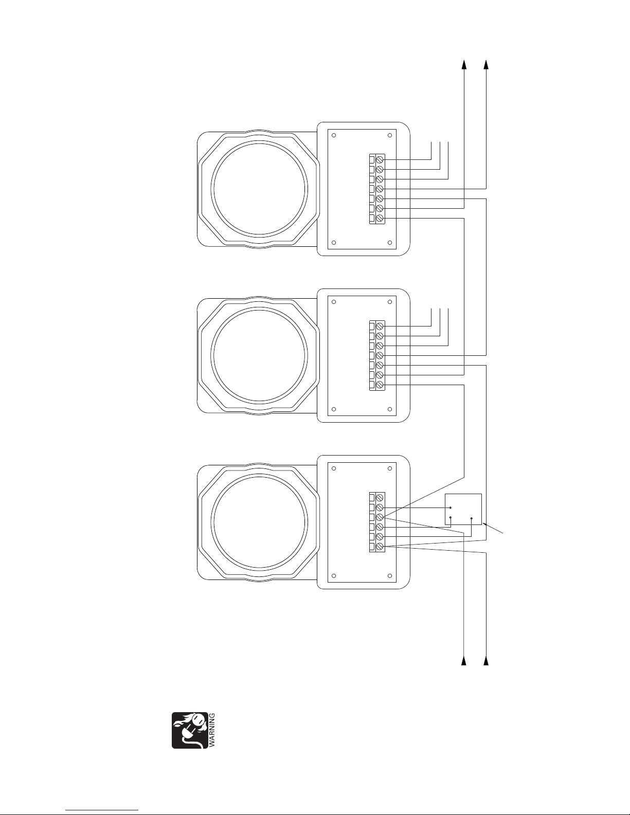
Wiring The 8741, 8742 and 8743 should be connected as shown in
Figures 5 and 6. Note any limitations on the number of
detectors and restrictions on the use of remote devices
permitted for each circuit.
The 8741 is used with the 8713 detector in the MPC-6000/
MPC-7000 System. The 8743 must be used for the relay
version. Also, all optional accessories in the same loop must
be compatible with the detector series being used. These
devices should be interconnected as shown in Figure 6 and
wired to the FDLC. (Refer to the FDLC Installation Instructions, P/N 315-447360FA, or the MPC-6000/MPC-7000
Manual, P/N 315-447309, as applicable.) 8710 and 8713 are
polarity insensitive detectors. Line 1 and Line 2 can be either
line of the loop. Note any limitations on the number of
detectors and restrictions on the use of remote devices
permitted for each circuit.
When replacing a detector with a different model, be aware
that existing detector accessories connected to the base or
air duct housing that were compatible with the old detector
may not be compatible with the new detector. Always read
the Installation Instructions accompanying the detector to
determine detector and accessory compatibility.
Installation Of Smoke Detectors
To Install:
• Remove cover by loosening the four screws. Take off the
cover and set it aside.
• Align detector with base and insert detector.
• Rotate detector
clockwise while gently pressing on it
until the detector drops fully into base.
• Then rotate the detector clockwise until it stops and
snaps in place.
• Replace cover and tighten the four screws.
To Remove:
• Rotate the detector counterclockwise until stop is
reached.
• Pull detector out of base.
Page 8
P/N 315-049708FA-48
LOOP WIRES.
SEE COMPATIBLE
CONTROL
EQUIPMENT TABLE.
NO
COM
NC
LOOP WIRES.
SEE COMPATIBLE
CONTROL
EQUIPMENT TABLE.
TO NEXT DETECTOR
OR EOL DEVICE
(1A)
TO REMOTE DEVICE
(6)
CNTL
+
-
(5)
-+
+
-
ALARM CONTACTS
125 VAC, 24 VDC, 2.5A
SEE NOTE 2
DEVICE
REMOTE
DEVICE LOOP
-
DEVICE LOOP
+
LOOP/REM
-
DEVICE
CONTROL
NOT USED
LOOP/REM
+
MODEL 8741
TO NEXT DETECTOR
OR EOL DEVICE
+
-
TO SECOND
REMOTE DEVICE
(SEE MULTIPLE
REMOTE DEVICES)
REM+
-
+
REM-
CONTL
REMOTE
ALARM
RELAY
COMNC NO
+
-
CNTL
-
+ +
DEVICE
LOOP
MODEL 8742
NOTE:
EOL DEVICE MUST BE
COMPATIBLE WITH
SYSTEM INITIATING
CIRCUIT. OBSERVE
PROPER POLARITY
WHERE APPLICABLE.
(6)
(5)
(1A)
TB1
TB1
8854 8854
NOTES:
1. Up to 30 air duct housings can be
installed on one initiating circuit,
except as noted in Note 2.
2. When an 8742 is used to control a fire
safety function, the 8742 must be the
ONLY device on the initiating circuit.
3. Do not use looped wire under base
terminal.
4. Break wire run to provide supervision
of connection.
5. The green grounding screw in the
wiring compartment of the air duct
housing is not used.
Figure 5
Typical Connections for the 8741 / 8742 Using 8854 Detectors
If remote devices are supported by the initiating
circuit, each detector/base may have up to 2
remote devices with the following configurations
and restrictions only:
MULTIPLE REMOTE DEVICES
Remote
Device 1
8741
8741
Remote
Device 2
8845, 8849
8844, 8848
Restrictions
See Note 2
See Note 2
†
SEE REMOTE DEVICE
INSTRUCTIONS FOR
WIRING DETAILS:
DEVICE
8845, 8849
8844, 8848
INSTALLATION
INSTRUCTIONS
P/N 315-094925FA
P/N 315-094926FA
If the relay contacts are
being used to control 120
VAC operated equipment,
ensure that the conduit is
properly attached to the
internal metal ground strap,
using the proper conduit
locking nuts. Failure to
provide proper grounding
may result in fatal
electrical shock and
violation of national and
local codes.
Page 9
9 P/N 315-049708FA-4
Figure 6
Typical Connections for the 8741 / 8743 Using 8710 and 8713 Detectors
NOTES:
1. The relay contacts are shown after a reset pulse, which represents the non-alarm condition.
2. Refer to the 8727W / 8727C Installation Instructions, P/N 315-033230FA.
3. The green grounding screw in the wiring compartment of the air duct housing is not used.
LINE 2
LINE 1
NOT USED
LINE1OR2
TO REMOTE TB1
OTHER LINE
TO REMOTE TB3
COM
NO
NC
NO
DEVICE
LOOP
OTHER
LINE
LINE
1OR2
RELAY
ALARM
COM
NC
COM
NO
NC
TB2
(6 or 5)
TB3
(5 or 6)
TB1
(1A)
TB1
TB1
TB1
MODEL 8741
MODEL 8743
MODEL 8743
8710
8713
OPTIONAL REMOTE ALARM
INDICATOR MODEL 8727C OR 8727W
SEE NOTE 2
LOOP WIRES.
SEE COMPATIBLE CONTROL
EQUIPMENT TABLE.
8710
8713
TO NEXT
ADDRESSABLE
DEVICE
ALARM CONTACTS
125 VAC, 24 VDC, 2.5A
SEE NOTE 1
ALARM CONTACTS
125 VAC, 24 VDC, 2.5A
SEE NOTE 1
NO
DEVICE
LOOP
OTHER
LINE
LINE
1OR2
RELAY
ALARM
COM NC
8710
8713
TO REMOTE TB2
If the relay contacts
are being used to
control 120 VAC
operated equipment,
ensure that the
conduit is properly
attached to the
internal metal
ground strap, using
the proper conduit
locking nuts. Failure
to provide proper
grounding may
result in fatal
electrical shock
and violation of
national and local
codes.
Page 10
P/N 315-049708FA-410
TESTING Only qualified service personnel should test these units. To
assure proper operation of the detector and control panel,
both the Sensitivity and the Functional tests should be
conducted. The minimum test schedule may be found in the
current edition of NFPA 72 for installations in the U.S.
Sensitivity Test The 8854 detector monitors its smoke sensitivity automati-
cally and requires no test equipment. A green flash of the
detector LED about every seven seconds indicates that the
smoke sensitivity is within its listed limits.
The following detector models are analog types that must
be programmed for the air duct application using the
control unit configuration tool; that is, CIS-4.
To test the 8713/8710 detector refer to its installation instructions. See Table A on page 11.
These tests ensure that the detector is within its listed and
marked sensitivity range. For additional instructions on
applying the Sensitivities mode, refer to the 8720 Manual,
P/N 315-033260FA.
Functional Test Smoke Testing
Using TG-11 smoke test canister with testing nozzle model
AD-TGN (purchased separately) available from Siemens
Industry, Inc., insert the test gas nozzle into the hole in the
red test plug in the unit cover. Press can against cover for
about
1
/2 second to release gas into the chamber.
DO NODO NO
DO NODO NO
DO NO
T SPRAT SPRA
T SPRAT SPRA
T SPRA
Y GAY GA
Y GAY GA
Y GA
S FOR MORE S FOR MORE
S FOR MORE S FOR MORE
S FOR MORE
THAN ½ SECONDTHAN ½ SECOND
THAN ½ SECONDTHAN ½ SECOND
THAN ½ SECOND
..
..
.
O O
O O
O
VER-VER-
VER-VER-
VER-
USE OF USE OF
USE OF USE OF
USE OF
TESTES
TESTES
TES
T GAT GA
T GAT GA
T GA
S MAS MA
S MAS MA
S MA
Y RESULY RESUL
Y RESULY RESUL
Y RESUL
T IN DETECTT IN DETECT
T IN DETECTT IN DETECT
T IN DETECT
OR CONOR CON
OR CONOR CON
OR CON
TT
TT
T
AMI-AMI-
AMI-AMI-
AMI-
NANA
NANA
NA
TION.TION.
TION.TION.
TION.
After 15 to 20 seconds the detector will go into alarm,
illuminating the detector LED and causing the duct unit
functions to operate; alarm relays will change state, and the
alarm related remote accessories, if attached, will function.
If no test gas is available to conduct functional testing,
remove cover and, while holding down the cover removal
switch, blow smoke from a smoldering cotton wick or punk
directly at the head to cause an alarm. The alarm indicator on
the detector should illuminate within one minute.
Page 11
11 P/N 315-049708FA-4
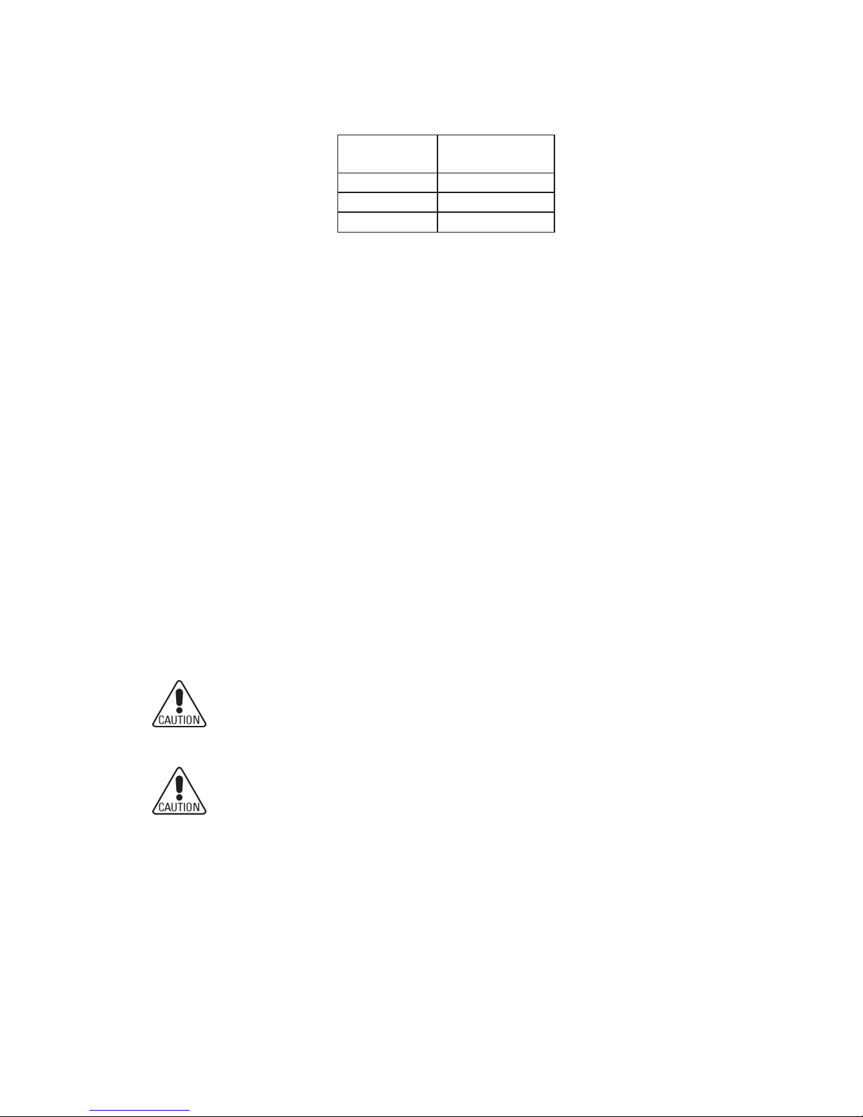
Refer to the following Installation Instructions for additional
information on testing each of these detectors:
The 8710 and 8713 can also be tested individually using the
8720. Refer to the 8720 Manual, P/N 315-033260FA.
MAINTENANCE The performance of the air duct detector unit may be
adversely affected by dirt or foreign matter on the sampling
tubes or detector. If the air holes in the input sampling tube
become restricted, the unit cannot receive a proper air
sample, and performance is impaired. It is recommended
that the sampling tubes be checked and cleaned periodically.
The detector maintenance program should consist of
periodic cleaning of dust from the detector head by using a
vacuum cleaner. For cleaning Models 8854, 8713 or 8710,
refer to the detector’s Installation Instructions (See Table A).
The cleaning and test program is recommended for 6 month
intervals, or more frequently, if needed, depending on the
individual detector environment. Consult your local code and
AHJ requirements for required maintenance schedules.
UnderUnder
UnderUnder
Under
no circumst no circumst
no circumst no circumst
no circumst
ances is the detances is the det
ances is the detances is the det
ances is the det
ectorector
ectorector
ector
por por
por por
por
tt
tt
t
ion of the unition of the unit
ion of the unition of the unit
ion of the unit
to be disassembled by anto be disassembled by an
to be disassembled by anto be disassembled by an
to be disassembled by an
yy
yy
y
one otherone other
one otherone other
one other
than an authoriz than an authoriz
than an authoriz than an authoriz
than an authoriz
eded
eded
ed
FF
FF
F
aradaarada
aradaarada
arada
y Sy S
y Sy S
y S
yy
yy
y
stst
stst
st
ems ems
ems ems
ems
TT
TT
T
ecec
ecec
ec
hnician.
hnician.
hnician.hnician.
hnician.
F F
F F
F
oror
oror
or
service, service,
service, service,
service,
cont cont
cont cont
cont
act yact y
act yact y
act y
ourour
ourour
our
nearest authoriznearest authoriz
nearest authoriznearest authoriz
nearest authoriz
ed Fed F
ed Fed F
ed F
aradaarada
aradaarada
arada
y Sy S
y Sy S
y S
ervice Rervice R
ervice Rervice R
ervice R
epresentepresent
epresentepresent
epresent
atat
atat
at
ii
ii
i
ve.ve.
ve.ve.
ve.
If the fire alarm syIf the fire alarm sy
If the fire alarm syIf the fire alarm sy
If the fire alarm sy
stst
stst
st
em is connectem is connect
em is connectem is connect
em is connect
ed to a central sted to a central st
ed to a central sted to a central st
ed to a central st
atat
atat
at
ion orion or
ion orion or
ion or
fire fire
fire fire
fire
depardepar
depardepar
depar
tment,tment,
tment,tment,
tment,
or or
or or
or
operat operat
operat operat
operat
es extes ext
es extes ext
es ext
ernal devices sucernal devices suc
ernal devices sucernal devices suc
ernal devices suc
h as fans,h as fans,
h as fans,h as fans,
h as fans,
ext ext
ext ext
ext
in-in-
in-in-
in-
guishers,guishers,
guishers,guishers,
guishers,
etc., etc.,
etc., etc.,
etc.,
connect connect
connect connect
connect
ed,ed,
ed,ed,
ed,
not
not
not not
not
ify appropriatify appropriat
ify appropriatify appropriat
ify appropriat
e personnel ande personnel and
e personnel ande personnel and
e personnel and
disconnect the extdisconnect the ext
disconnect the extdisconnect the ext
disconnect the ext
ernal devices unternal devices unt
ernal devices unternal devices unt
ernal devices unt
il all til all t
il all til all t
il all t
ests are completests are complet
ests are completests are complet
ests are complet
ed.ed.
ed.ed.
ed.
AfAf
AfAf
Af
tt
tt
t
erer
erer
er
t t
t t
t
estest
estest
est
ing,ing,
ing,ing,
ing,
reset the sy reset the sy
reset the sy reset the sy
reset the sy
stst
stst
st
em,em,
em,em,
em,
reconnect the devices, reconnect the devices,
reconnect the devices, reconnect the devices,
reconnect the devices,
and not and not
and not and not
and not
ifyify
ifyify
ify
the personnel that the sythe personnel that the sy
the personnel that the sythe personnel that the sy
the personnel that the sy
stst
stst
st
em is operatem is operat
em is operatem is operat
em is operat
ing aging ag
ing aging ag
ing ag
ain.ain.
ain.ain.
ain.
AELBAT
rotceteD
noitallatsnI
noitcurtsnI
4588AF891490-513
3178AF092330-513
0178AF092330-513
Page 12
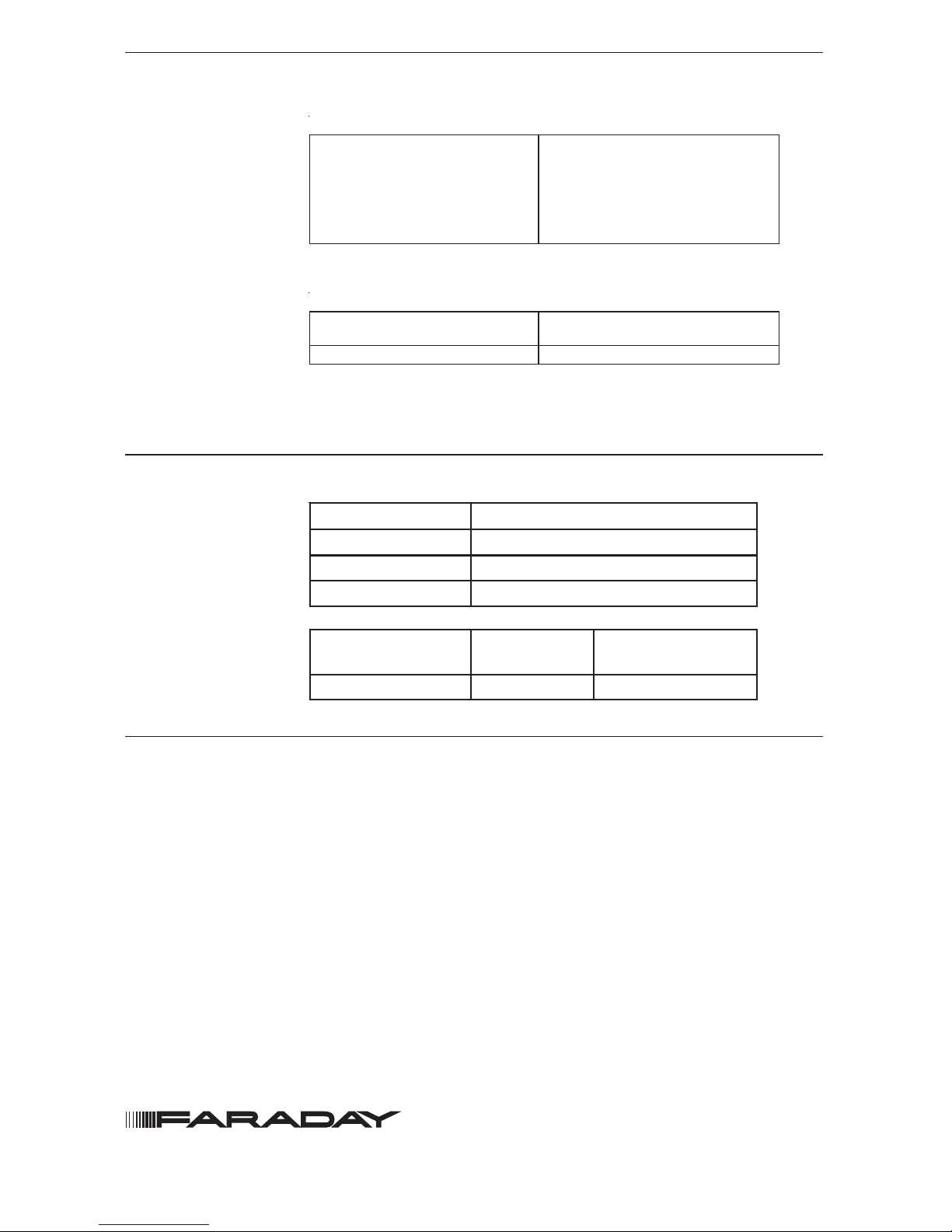
COMPATIBLE CONTROL EQUIPMENT
ELECTRICAL RATINGS FOR 8713 AND 8710
Electrical ratings are not provided here for these detectors.
Guidance for detector loop loading, along with loop wire
electrical specifications are provided in the applicable control
unit instructions given in the above Compatible Control
Equipment tables.
Siemens Industry, Inc.
Building Technologies Division
Florham Park, NJ P/N 315-049708FA-4
ROTCETED4588GNISU2478DNA1478
tnempiuqEeludoM
reifitnedIytilibitapmoC
/noitallatsnIeludoM
snoitcurtsnIgnir
iW
5078)0007-CPM/0006-CPM(5-AF058430-513N/P
104-WL 3-AF799590-513N/P
)104-WL(A4-EZWL 4-AF810690-513N/P
)104-W
L(A8-EZWL 3-AF220690-513N/P
ROTCETED3178RO0178GNISU3478DNA1478
tnempiuqEeludoM
reifitnedIytilibitapmoC
/noitallatsnIeludoM
snoitcurts
nIgniriW
)0007-CPM/0006-CPM(CLDF6-903744-513N/P
The detector model number is the compatibility identifier.
ELECTRICAL RATINGS FOR 8854
egatloVCDV72-61
elppiRkaep-ot-kaepV3
tnerruCyrosivrepuS.xamAu011
emiTpu-tratS.xamsdnoces05
rotceteD4588
+rotce
teD4588
eciveDetomeR
tnerruCmralAAm05-33Am07-05
 Loading...