

Page 1

INSTALLATION INSTRUCTIONS AND WIRING FOR
P/N 8710 ADDRESSABLE PHOTO DETECTOR AND
P/N 8713 ADDRESSABLE PHOTO/THERMAL DETECTOR AND
P/N 8712 ADDRESSABLE THERMAL DETECTOR
The 8710/8713/8712 Addressable Detectors allow
smoke and/or heat detection on an Addressable
Device Circuit of a fire alarm control unit. A
multicolor LED indicates the condition of the
detector. This multicolor LED displays red for
alarm/output active, yellow for trouble, and green
for normal operation. The 8710/8713/8712 Addressable Detectors each use one address on the
Addressable Device Circuit. It does not require
any mechanical address programming. Use the
8720 Device Programmer to program and test
each detector.
These instructions are written in accordance with
the installation guidelines of NFPA 72, National Fire
Alarm Code.
CAUTION: Detector Device Storage
DO NOT install this detection device until all
construction is completed.
DO NOT store this detection device where it
can be contaminated by dirt, dust, or humidity.
DETECTOR PLACEMENT FOR 8710/8713
Although no specific spacings are set for the
detectors used for a clean air application, use 30
foot center spacing (900 sq ft) from NFPA
Standard 72, if practical, as a guide or starting
point for a detector installation layout. This
spacing, however , is based on ideal conditions smooth ceiling, no air movement, and no physical
obstructions. In some applications, therefore,
considerably less area is protected adequately by
each smoke detector. This is why it is mandatory to
closely follow the installation drawings. In all
installations place the detector on the ceiling, a
minimum of 6 inches from a side wall, or on a wall,
4 to 6 inches from the ceiling.
T o avoid nuisance alarms
Do not locate the detectors where excessive
smoke concentrations exist under normal
conditions, or in areas of prolonged high relative
humidity where condensation occurs.
Do not locate the detectors next to an oil burner,
kitchen, or garage where exhaust fumes can
trigger an alarm. Other causes of false alarm are
dust accumulation, heavy concentrations of steam,
heavy pipe or cigar smoke, and certain aerosol sprays.
Air Currents
Before a detector can sense a fire, the products of
combustion or smoke must travel from the fire to
the detector. This travel is especially influenced by
air currents; therefore, consider air movement
when designing the system. While combustion
products tend to rise, drafts from hallways, air
diffusers, fans, etc., may help or hinder the travel
of combustion products to the detector. When
positioning a detector at a particular location, give
consideration to windows and doors, both open and
closed, to ventilating systems, both in and out of
operation, and to other factors influencing air
movement. Do not install a detector in the air
stream of a room air supply diffuser . It is better to
position a detector closer to an air return.
The distance that products of combustion or
smoke travel from a fire to the detector is not
usually the shortest linear route. Combustion
products or smoke usually rise to the ceiling, then
spread out. A verage ceiling height s of 8 to 10 feet
do not abnormally affect detector response. High
ceilings, located in churches, warehouses,
auditoriums, etc., do affect detector response and
should be considered.
Special Ceiling Construction Factors
Ceiling obstructions can change the natural
movement of air and combustion products. Take
obstructions created by girders, joists, beams, air
conditioning ducts, or architectural design into
consideration when determining area protection.
Consider girders, joists, or beams 8 inches or less
in depth equivalent to a smooth ceiling in view of
the spillover effect of smoke. If obstructions are
over 8 inches in depth, movement of heated air
and smoke may be slowed by the pocket or bay
formed by the girders, joists, or beams. In this
case, reduce spacing. If obstructions exceed 18
inches in depth and are more than 8 foot centers,
treat each bay as a separate area requiring at least
one detector.
FARADAY
PAGE 1 OF 4 P/N 315-033290FA -3
Page 2
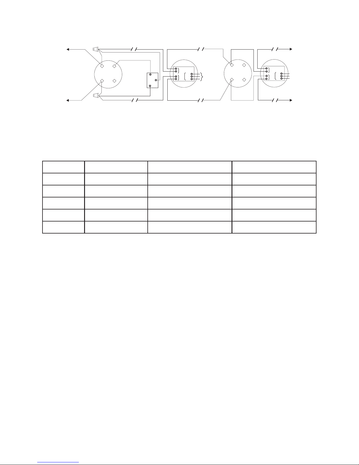
T
LINE 1**
T
FROM ADDRESSABLE DEVICE
CIRCUIT OF A COMPATIBLE
CONTROL UNIT OR PREVIOUS
ADDRESSABLE DEVICE
LINE 2**
N/PesaBnoitpircseDN/PnoitcurtsnInoitallatsnI)s(rotceteDelbitapmoC
3588esaBAF391490-5133178dna2178,0178
8853 BASE
(WITH REMOTE DEVICE)
561a
*The relay contacts are shown in the system normal condition.
**8710/8712/8713 are polarity insensitive detectors. Line 1 and Line 2 can be either line of the loop.
Current draw for 8710/8712/8713 detectors is 1mA.
1b
OPTIONAL
REMOTE
ALARM
INDICATOR
MODELS
8727W / 8727C
TB2
8716 REMOTE RELAY BASE
(NO REMOTE DEVICE)
TB1
TB3
5+
NO
6–
NC
RELAY*
CONTACTS
C
3A, 120 VAC
3A, 30 VDC
RESISTIVE
561a
1b
Figure 1
Typical Wiring Diagram for 8710/8712/8713 Detector Bases
TO NEXT BASE
5+
NO
C
6–
NC
TO NEXT BASE
DO NO
USE AN
END OF
LINE
DEVICE
DO NO
USE AN
END OF
LINE
DEVICE
5178esa
BelbiduAAF022330-5133178dna2178,0178
6178esaByaleRAF022330-5133178dna2178,0178
0488gnisuoHtcuDAF956590-5130178
7
178yaleR/wgnisuoHtcuDAF082330-5130178
Base/Detector Compatibility
DETECTOR PLACEMENT FOR 8712
Locate the 8712 on the ceiling, at least 4 inches
from the side walls. For an ideal, smooth ceiling
condition, place the detectors at a maximum
center spacing of 50 feet (2500 square feet), 25
feet from side walls or room partitions.
Actual job conditions and sound engineering
judgment must determine detector spacing.
Consider environmental factors including ambient
temperature fluctuation, and the nature of the fire
hazard. Room or area configuration and ceiling
type (sloped or flat, smooth or beamed) also
dictates placement.
TEMPERA TURE – HUMIDITY – PRESSURE
– AIR VELOCITY
The temperature range for the 8710/8713 detector
is 32°F (0°C) to 100°F (38°C). The 8712 thermal
alarm temperature is fixed at 135°F (57°C) with a
rate of rise option set through the control unit. Use
these detectors in environments where the
Table 1
humidity does not exceed 93% (non-condensing).
Normal changes of atmospheric pressure do not
affect detector sensitivity . For open area 0-1200 f t/
min applications, use the appropriate application
from the ASD application list. Use the ASD duct
application for 300-4000 ft/min applications a) in
above-ceiling and under-floor plenums, b) inside
an air duct, and c) in an air duct housing using
sampling tubes. Follow detector spacing and
location requirements in NFP A 72 Chapter 5 for
High Air Movement Areas and Control of Smoke
Spread.
In air duct applications, the 8710 requires a
Faraday 8840 or 8717 Duct Housing and appropriate sampling tube. When installing the 8710 in
existing installations with an existing duct detector
housing, order P/N 500-695967 and use it in that
installation. This kit includes the required housing
cover, P/N 305-095676. Do not use the 8710 with
any other air duct cover.
PAGE 2 OF 4 P/N 315-033290FA -3
Page 3

IMPORTANT NOTE
In air duct and open area applications, the
8710/8712/8713 smoke sensitivity range is
indicated on its nameplate.
DETECTOR PROGRAMMING
Each 8710/8713/8712 detector must be
programmed to respond to a unique loop address.
1. Program the detector address, using the
Faraday 8720 Device Programmer. Refer to the
USER'S MANUAL, P/N 315-033260F A.
2. Record the loop number and device address on
the detector label and associated base label.
The optional 8720 label printer can be used for
this purpose.
DETECTOR MOUNTING
The 8710/8713/8712 detectors are compatible with
the bases, as shown in Table 1. Follow the base
installation instructions for proper wiring.
To ensure proper installation of the detector into
the base, be sure the wires are properly dressed:
1. Position all wires flat against the base.
2. Take up all slack in the outlet box.
3. Route wires away from connector terminals.
To Install:
1. Align LED in detector with LED symbol on base
and insert detector into base.
2. Rotate detector counterclockwise while gently
pressing on it until the detector drops fully into
base.
3. Then rotate the detector clockwise until it stops
and locks into place. Insert optional locking
screw Faraday 8846.
To Remove:
1. Loosen locking screw, if inst alled. Then rotate
the detector counter-clockwise until stop is
reached.
2. Pull detector out of the base.
TESTING AND SENSITIVITY
MEASUREMENT
The recommended requirement for the smoke
and heat detector maintenance consists of a
semiannual visual inspection and annual
functional testing.
For functional testing of the 8710 and 8713
smoke detectors, use the Faraday 8919 Smoke
Detector Aerosol, following the directions provided
with the aerosol.
For functional testing of the 8713 and 8712
thermal detectors, use a hair dryer (1000-1500
watts) with the heated air blown at the thermal
element.
The control unit automatically indicates the trouble
message "Maint Alert" for the 8710/8713 smoke
detector whose smoke chamber changes to the
level where the set sensitivity cannot be
maintained. In such circumstances, the detector
may require cleaning as a result of dust or debris
accumulation; follow the 8710/8713 CLEANING
PROCEDURE steps. Required cleaning intervals
vary greatly and should be geared to the individual
detector environment.
The 8710/8713/8712 detectors can also be
electrically tested using the Faraday 8720 Device
Programmer. Refer to the USER'S MANUAL, P/N
315-033260FA.
PAGE 3 OF 4 P/N 315-033290FA -3
Page 4
W
W
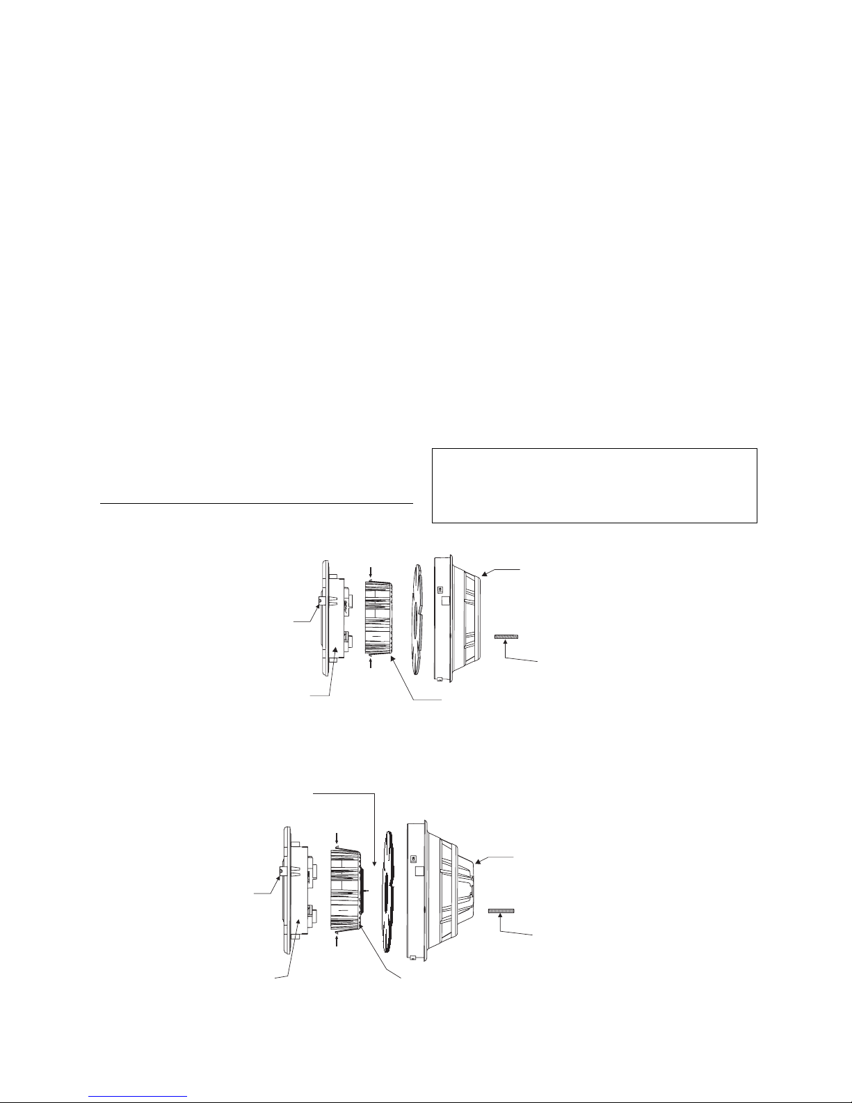
8710/8713 CLEANING PROCEDURE*
(See Figure 2 and 3)
1. Notify the proper personnel that the fire alarm
system is being serviced.
2. Remove the detector to be cleaned from its
base. (See removal section.)
3. Using a small blade screwdriver, remove the
cover from the rest of the detector by releasing
the 2 cover tabs located on the outside of the
cover. Sep arate the foam screen from the
cover.
4. Remove the labyrinth from the sensing chamber by squeezing the labyrinth sides along the
release axis and pulling out. For the 8713, be
sure not to damage or disconnect the thermal
wires.
5. Clean dust from the detector cover, foam
screen, sensing chamber and labyrinth using a
brush, or by blowing with compressed air.
CAUTION: Do not use a compressed air
supply that may contain an oil residue.
* The 8712 cannot be cleaned in the field.
WARNING: Do not remove or loosen the two
screws on the rear of the detector, or calibration
will be lost.
NOTE: The insect screen and labyrinth may be
replaced with new parts, using the Faraday 8850
Detector Maintenance Kit.
NOTE: Do not disconnect the thermal wires from
the detector.
6. Reassemble the detector by reversing the
steps used for disassembly, and reinstall in its
base.
7. Test the detector. (See TESTING AND SENSITIVITY MEASUREMENT section of these
instructions.) Reset the control unit after each
alarm.
8. When all service has been completed, notify
personnel that system service has been
restored.
CAUTION:
NO FIELD REP AIR OF THE DETECT ORS
SHOULD BE ATTEMPTED. THE DETECTORS
ARE FACT ORY REP AIRABLE ONLY.
COVER TAB
COVER TAB
SENSING
CHAMBER
SENSING
CHAMBER
THERMAL
(MATCHES AXIS
OF REAR SCREWS)
RELEASE
AXIS
RELEASE
AXIS
(MATCHES AXIS
OF REAR SCREWS)
Figure 2
8710 Assembly
RELEASE
AXIS
RELEASE
AXIS
LABYRINTH
Figure 3
8712/8713 Assembly
LABYRINTH
COVER
FARADAY 8846
LOCKING SCRE
(OPTIONAL)
COVER
FARADAY 8846
LOCKING SCRE
(OPTIONAL)
PAGE 4 OF 4 P/N 315-033290FA -3
 Loading...