

Page 1
INSTALLATION INSTRUCTIONS AND WIRING FOR
ADDRESSABLE INTERFACE MODULES
P/N 8702, 8703 AND 8704
INTRODUCTION
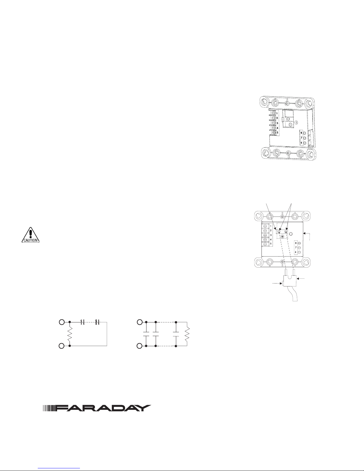
The 8702/8703/8704 Addressable Modules, shown in Figure 1, interface
normally open contact devices to an Addressable Device Circuit of a fire alarm
control unit.
The 8702 and 8704 can monitor a normally open or closed dry contact. The
8702 can only monitor and report the status of the contact, while the 8704
incorporates an addressable Form C relay. The 8703 is a dual input module that
supervises and monitors two sets of dry contacts.
A multicolor LED, visable through the cover plate, indicates the condition of the
initiating device circuit. This multicolor LED displays red for alarm, yellow for
trouble and green for normal operation.
Figure 1
8702/8703/8704 Module
PROGRAMMING INSTRUCTIONS
Refer to Figure 2 to locate the opening on the module cover that allows
access to the programming holes which are on the module printed circuit
board.
To prevent potential damage to the 8720 DO NOT connect a module to
the 8720 until at least one wire is removed from terminals 1 or 2 of the
module.
1. Plug the programming cable of the Faraday 8720 Programmer/Tester
into the two-pin receptacle on the module. (See Figure 2 for location.)
2. Set the address for the module by following the instructions in the 8720
Programmer/Tester Manual (P/N 315-033260FA). Refer to Figure 3 for
setting normally open and normally closed switches.
3. Record the device address on the label located on the module. The
module can now by installed and wired to the system.
NORMALLY CLOSED SWITCHES
(SEE NOTE 4)
ENDOFLINE
RESISTOR
470 OHMS,
1/4W
NOTES:
1. There can be any number of normally closed or normally open switches.
2. The end of line resistor must be located at the last switch for normally open switches.
3. Do not wire a normally closed switch across the end of line resistor.
4. Only for use with status applications.
NORMALLY OPEN SWITCHES
(SEE NOTES 2 AND 3)
ENDOFLINE
RESISTOR
470 OHMS,
1/4W
SLOT FOR
LOCATING TAB
LOCATING
TAB
PROGRAMMING
HOLES
MODULE
PLUG FROM
8720
PROGRAMMER/
TESTER
Figure 2
Connecting The 8720 Plug
Figure 3
Wiring Switches
Siemens Industry, Inc.
Building Technologies Division • Florham Park, NJ
Tel: (973) 593-2600 • Fax: (973) 593-6670
Web: www.faradayfirealarms.com
P/N 315-049475FA-5 PAGE 1 OF 4
Page 2
MOUNTING
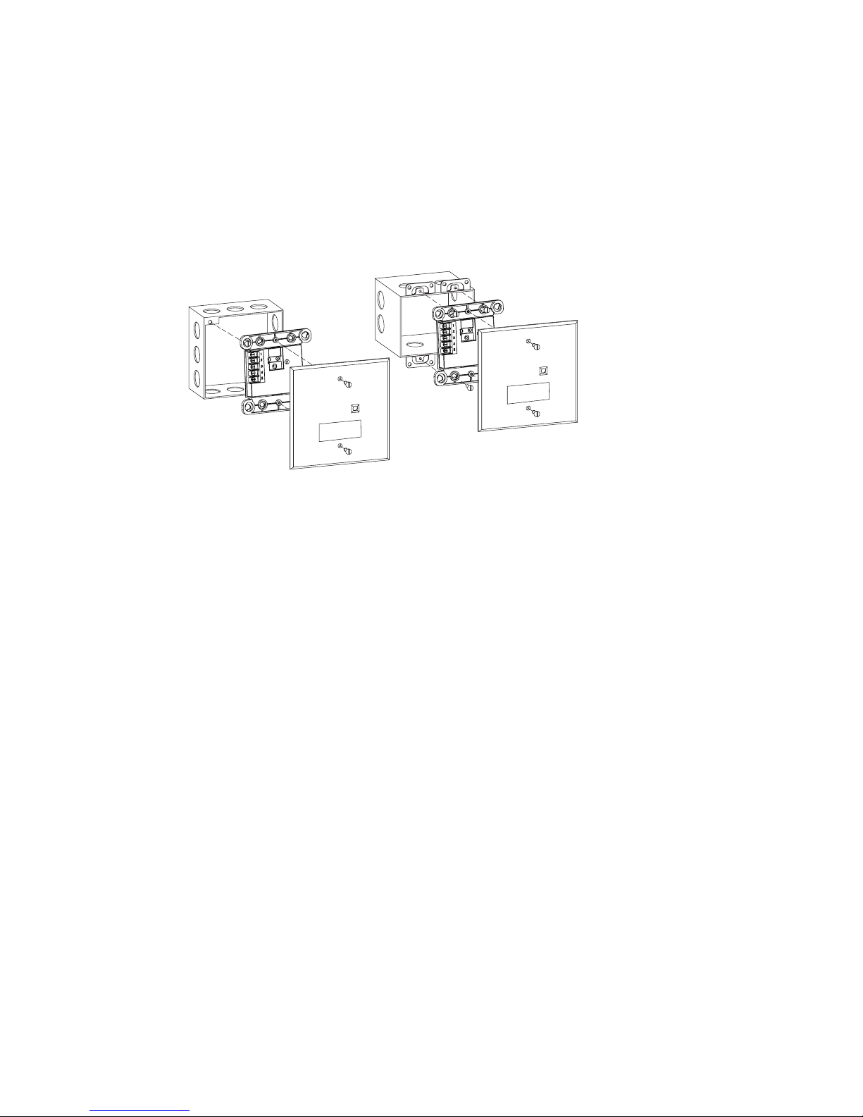
(Refer to Figure 4) Addressable Interface Models 8702, 8703, and 8704 mount directly into a (user supplied) double gang or 4 inch switchbox. Fasten the module to the switchbox with the switchplate using the
2 screws provided.
A red LED will blink to indicate an off-normal input switch position and/or an internal relay transfer.
NOTE: Be sure to program the module before fastening the switchplate to the unit.
DOUBLE GANG BOX
3 1/2-INCHES DEEP
4-INCH SQUARE BOX
2 1/8-INCHES DEEP
SWITCHPLATE
5-INCHES SQUARE
SWITCHPLATE
5-INCHES SQUARE
(SUPPLIED)
Figure 4
8702/8703/8704 Mounting
(SUPPLIED)
WIRING
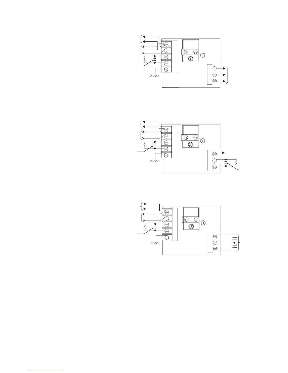
(Refer to Figures 7 - 9 ) Refer to the appropriate wiring diagram and wire the addressable interface module
accordingly.
NOTE: Recommended wire size: 18 AWG minimum, 14 AWG maximum
Wire larger than 14 AWG can damage the connector.
Power Limited Wiring
In compliance with NEC Article 760, all power limited fire protective signaling conductors must be separated a minimum of ¼ inch from all of the following items located within an outlet box:
• electric light
• power
• Class 1 or non-power limited fire protective signaling conductors
To meet the above the requirements, the following guidelines must be observed when installing this
interface module.
NOTE: If power limited wiring is not used within this outlet box, then these guidelines do not
apply. In that case, be sure to follow standard wiring practices.
8704 Wiring Barrier
The Wiring Barrier must be used when the 8704 relay contacts are connected to non-power limited wires.
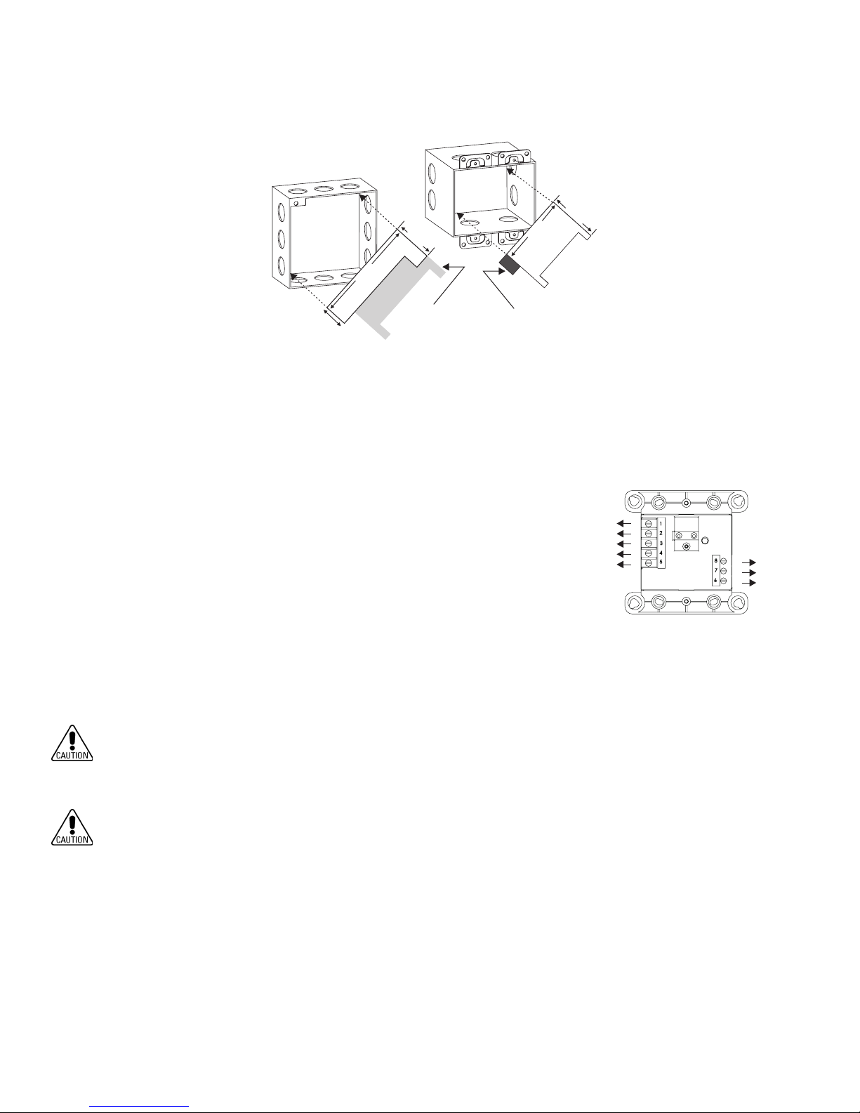
Break apart the barrier to the correct size and shape shown in Figure 5 for either the 4-inch square or
double gang box. Install the barrier diagonally into the backbox to create two separate compartments
within the backbox to separate the wires, as shown in Figure 5.
P/N 315-049475FA-5 PAGE 2 OF 4
Page 3
4-INCH SQUARE BOX
2 1/8-INCHES DEEP
DOUBLE GANG BOX
3 1/2-INCHES DEEP
3.25 in
1.187 in
5.06 in
2.0 in
BREAK OFF THIS
SECTION WHEN
USING A 4-INCH
SQUARE BOX
4.5 in
BREAK OFF THIS
SECTION WHEN
USING A DOUBLE
GANG BOX
Figure 5
Installing the 8704 Control Module Barrier
Wiring Entering Outlet Box
All power limited wiring must enter the outlet box separately from the electric
light, power, Class 1, or non-powered limited fire protection signaling conductors. For the 8704, wiring to terminal block positions 1, 2, 3, 4, and 5 must enter
the outlet box separately from terminals 6, 7, and 8.
NOTE: Minimize the length of wire entering the outlet box.
WIRING AT THE TERMINAL BLOCKS
Power Limited Wiring
(Refer to Figure 6.) Wiring to positions 1, 2, 3, 4, and 5 is power limited.
Non-Power Limited Wiring
Wiring to positions 6, 7, and 8 is considered non-power limited.
WIRES CONNECTED TO TERMINALS
1 THROUGH 5 TO ENTER/EXIT
ELECTRICAL BOX OPPOSITE SIDE
FROM WIRES CONNECTED TO
TERMINALS 6 THROUGH 8.
P
P
P
P
P
P = POWER LIMITED
N = NON-POWER LIMITED
N
N
N
Figure 6
8704 Power Limited Wiring
Ground shield ONLY at the specified location on the Control Panel.
NOTE: Terminal 5 of the module must be connected to a known good earth ground for proper
operation.
EOL device must be a 470 ohm, 1/4 W resistor. When replacing an existing 8702/8703/8704 on a device
loop, you must also replace the EOL resistor if it is not 470 ohms, 1/4W.
P/N 315-049475FA-5 PAGE 3 OF 4
Page 4
NOTES:
LINE 1
LINE 1
LINE 2
LINE 2
SEE NOTE 7
NOT USED
TO NEXT
ADDRESSABLE DEVICE
END OF LINE DEVICE
SEE NOTE 2
END OF LINE DEVICE
SEE NOTE 2
SUPERVISED SWITCH
SEE NOTES 1 AND 5
SUPERVISED SWITCH
SEE NOTES 1 AND 5
FROM ADDRESSABLE DEVICE
CIRCUIT OF THE CONTROL
UNIT OR THE PREVIOUS
ADDRESSABLE DEVICE
1
2
3
4
5
8
7
6
1. All supervised switches
must be held closed and/or
open for at least a quarter of
a second to guarantee
detection.
2. End of line device: 470 ohm,
1/4W resistor, P/N 140-
820164.
3. Module is polarity insensi-
tive. Line 1 and Line 2 can
be either line of the loop.
4. 8702/8703/8704 draws
1.3mA from the addressable
device circuit.
5. Supervised switch ratings:
Style B, Class B, See
NFPA72 standard for the
number of normally open
contact devices allowed.
Voltage maximum: 27 VDC
Current maximum: 6mA
during polling
Contact resistance
maximum:
10 ohms
Maximum cable length:
200 feet (18 AWG)
C
: 0.02uF
Line to line
C
Max line size: 14 AWG
Line to shield
: 0.04uF
Min line size: 18 AWG
6. Relay contact ratings:
4A, 125 VAC
resistive
4A, 30 VDC resistive
Inductive:
3.5A, 120 VAC (0.6 P.F.)
3.0A, 30 VDC (0.6 P .F.)
2.0A, 120 VAC (0.4 P.F.)
2.0A, 120 VAC (0.35
P.F.)
2.0A, 30 VDC (0.35 P .F.)
The relay is shown in
standby condition.
7. Terminal 5 must be
connected to earth ground.
a. Use wire nuts to pass the
shield wire through the
electrical box with NO
connection to the device
terminal block or to local
ground.
b. Use shielded wire to
connect the switch wiring.
c. Tie the switch wiring shield
to terminal 5 or the local
earth ground.
ADDRESSABLE DEVICE
FROM ADDRESSABLE DEVICE
CIRCUIT OF THE CONTROL
UNIT OR THE PREVIOUS
ADDRESSABLE DEVICE
SUPERVISED SWITCH
SEE NOTES 1 AND 5
ADDRESSABLE DEVICE
FROM ADDRESSABLE DEVICE
CIRCUIT OF THE CONTROL
UNIT OR THE PREVIOUS
ADDRESSABLE DEVICE
SUPERVISED SWITCH
SEE NOTES 1 AND 5
TO NEXT
END OF LINE DEVICE
SEE NOTE 2
SEE NOTE 7
TO NEXT
END OF LINE DEVICE
SEE NOTE 2
SEE NOTE 7
LINE 1
LINE 2
LINE 1
LINE 2
LINE 1
LINE 2
LINE 1
LINE 2
1
2
3
4
5
Figure 7
8702 Wiring
Figure 8
8703 Wiring
1
2
3
4
5
Figure 9
8704 Wiring
8
7
NOT USED
6
8
7
RELAY CONTACTS
SEE NOTE 6
6
P/N 315-049475FA-5 PAGE 4 OF 4
 Loading...