

Page 1
INSTALLATION INSTRUCTIONS AND WIRING FOR
ADDRESSABLE MANUAL PULL STATION
P/N 8700-S AND 8700-D
INTRODUCTION
The Model 8700-S and 8700-D Manual Stations are addressable devices containing advanced control
panel communication technology. This technology, which provides two-direction communication with the
control panel, produces an Intelligent Initiating Device. The 8700-S is single action; the 8700-D is double
action.
PROGRAMMING INSTRUCTIONS
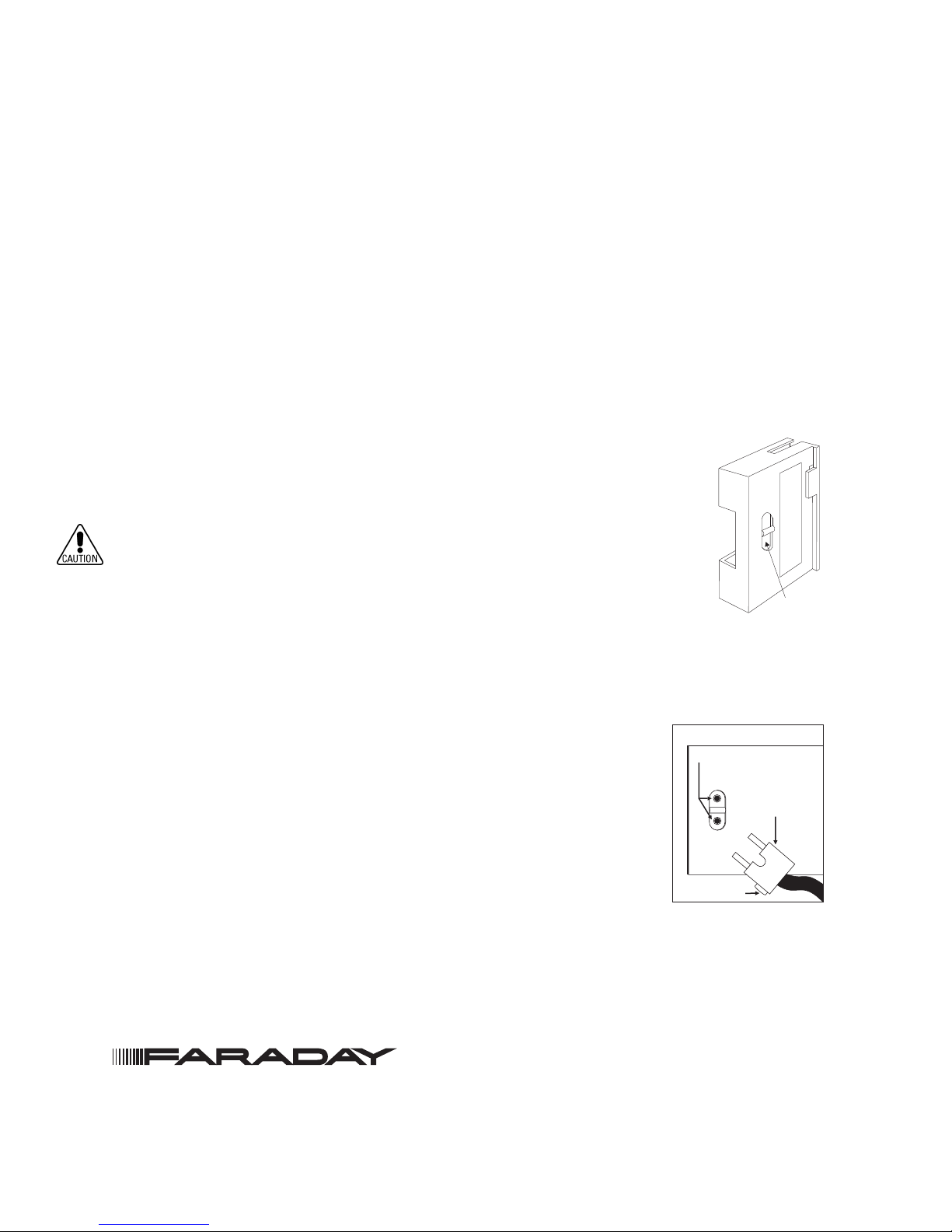
Refer to Figure 1 to locate the opening on the 8700 cover that allows access to the programming holes
which are on the 8700 printed circuit board.
To connect the 8700 to the 8720 Programmer/Tester, insert the plug from the cable
provided with the Programmer/Tester into the opening on the 8700 as shown in
Figure 2. Because 8700 devices are polarity insensitive, the programming plug can be
inserted into the programming holes in either direction.
To prevent potential damage to the Programmer/Tester, DO NOT connect an
8700 to the 8720 Programmer/Tester until at least one wire is removed from
terminals 1 or 2 of the 8700.
Follow the instructions in the 8720 Manual (P/N 315-033260FA) to program the 8700
to the desired address. Record the device address on the label located on the 8700
front Panel. The 8700 can now be installed and wired to the system.
OPERATION
The 8700-S and 8700-D manual stations operate with the Fire Alarm Control
Panel via the addressable device circuit.
The 8700-S and 8700-D manual station housings have a pull down lever that
locks in position after releasing a spring loaded switch. (See Figure 4.) To
indicate the manual station is activated, the pull down lever remains down and
locked until the station is physically reset.
The 8700-D has an additional lever labeled PUSH IN which must be operated
first.
Both models are reset by opening the hinged housing cover with an Allen key
and then closing and locking the cover.
Connecting the 8720 Plug
Figure 1
8700 Cover
PROGRAMMING
POINTS
LOCATING TAB
Figure 2
OPENING TO
PROGRAMMING
POINTS
PLUG FROM
8720
Siemens Industry, Inc.
Building Technologies Division • Florham Park, NJ
Tel: (973) 593-2600 • Fax: (973) 593-6670
Web: www.us.sbt.siemens.com/faraday
P/N 315-033200FA-5
PAGE 1 OF 2
Page 2
WIRING
NOTES:
1. Recommended wire sizes:
18 AWG minimum, 14 AWG maximum
1
2
3
LINE 1
2LINE
1LINE
2LINE
TO NEXT ADDRESSABLE DEVICE
FROM INITIATING CONTROL PANEL
OR PREVIOUS ADDRESSABLE DEVICE
EARTH GROUND
2. Wire larger than 14 AWG can damage the connector.
3. When using shielded cable without metal raceway or with
nonmetallic raceway, the shields should be terminated at the device
ground terminal. If the device box is already grounded by another
means, such as being mounted to a grounded structure, the wire
shields should be continuous and must be grounded solely at the point
of origin; for example, at the control panel.
4. When using shielded cable with metal raceway, the wiring shields
shall be continuous and grounded solely at the point of origin. The
device ground terminal shall be connected to the grounded device
Figure 3
Wiring Information
box.
5. When using metal raceway without shielded cable, connect the
device ground terminal to the grounded device box.
6. Metal raceway should be thoroughly grounded throughout the system.
7. The 8700-S and 8700-D draw 1mA from the addressable device
circuit.
8. The 8700-S and 8700-D are polarity insensitive devices. Line 1 and
INSTALLATION
Line 2 can be either line of the loop.
Distribute the manual station boxes throughout the protected area so that they
are unobstructed, readily accessible, and located in the normal exit path. Place the manual station according to the regulations of the authorities having jurisdiction.
Surface Mounting
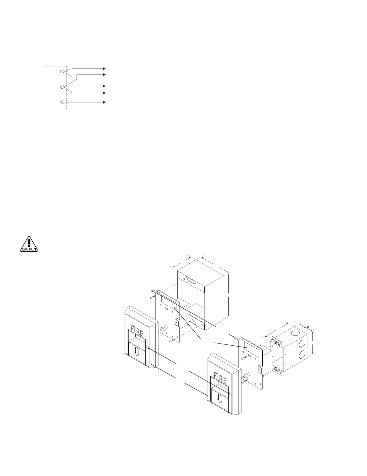
Mount the backplate to a Faraday Model 8864 Backbox as shown in Figure 4.
Flush Mounting
Mount the backplate to a user supplied single gang switchbox.
Do not overtighten the screws. Overtightening may distort the backplate.
SURFACE
MOUNTING
ENCLOSURE
BACKPLATE
2¾ in.
LOCKING
SCREW
HOUSING
MODEL
NAMEPLATE
SB-5R
4in.
5½ in.
HOUSING HINGED
TO BACKPLATE
BACKPLATE
3½ in.
3½ INCH DEEP
SWITCH BOX
(USER SUPPLIED)
3in.
P/N 315-033200FA-5
Figure 4
Mounting
PAGE 2 OF 2
FLUSH
MOUNTING
ENCLOSURE
 Loading...