

Page 1

KJ 45/S
- ISTRUZIONI ORIGINALI
I
RIVETTATRICE OLEOPNEUMATICA
PER INSERTI M4/M12
ISTRUZIONI D’USO - PARTI DI RICAMBIO
- TRANSLATION OF ORIGINAL INSTRUCTIONS
GB
HYDROPNEUMATIC TOOL
FOR INSERTS M4/M12
INSTRUCTIONS FOR USE - SPARE PARTS
- TRADUCTION DES INSTRUCTIONS ORIGINALES
F
MACHINE A SERTIR OLEOPNEUMATIQUE
POUR INSERTS M4/M12
MODE D’EMPLOI - PIECES DETACHEES
- ÜBERSETZUNG VON ORIGINALANLEITUNGEN
D
PNEUMATISCH-HYDRAULISCHES NIETWERKZEUG
FÜR BLINDNIETMUTTERN M4/M12
BEDIENUNGSANLEITUNG - ERSATZTEILE
KJ 45/S
- TRADUCCION DE LAS ISTRUCCIONES ORIGINALES
E
REMACHADORA OLEONEUMATICA
PARA TUERCAS M4/M12
INSTRUCCIONES DE USO - PIEZAS DE REPUESTO
- TŁUMACZENIE ORYGINALNEJ INSTRUKCJI
PL
NITOWNICA OLEO-PNEUMATYCZNA
DO NITONAKRĘTEK M4/M12
INSTRUKCJA OBSŁUGI - CZĘŚCI ZAMIENNE
- ПЕРЕВОД ОРИГИНАЛЬНЫХ ИНСТРУКЦИЙ
RUS
МАСЛЯНО – ПНЕВМАТИЧЕСКИЙ ЗАКЛЁПЫВАЮЩИЙ АППАРАТ
ДЛЯ ВСТАВОК М4/М12
ИНСТРУКЦИИ ПО ИСПОЛЬЗОВАНИЮ - ДЕТАЛИ
Page 2

KJ 45/S
KJ 45/S
La sottoscritta Far S.r.l., con sede in Quarto Inferiore (BO)
I
alla via Giovanni XXIII n° 2,
DICHIARA
sotto la propria esclusiva responsabilità che la rivettatrice
Modello: KJ 45/S - Rivettatrice oleopneumatica Utilizzo:
per inserti filettati M4-M12 alla quale questa dichiarazione
si riferisce è conforme ai requisiti essenziali di sicurezza
previsti dal D. Lgs. 17/2010 di recepimento della Direttiva
Macchine 2006/42/CE e successive modificazioni ed
integrazioni. La persona autorizzata a costituire il fascicolo
tecnico risponde al nome di Giacomo Generali, presso
la Far S.r.l., con sede in Quarto Inferiore (BO) alla via
Giovanni XXIII n° 2.
The undersigned Far S.r.l., having its office in Quarto
GB
Inferiore (BO), Via Giovanni XXIII No. 2, herewith
DECLARES
on its sole responsability that the riveting machine
Type: KJ 45/S - Hydropneumatic tool
Application: for blind rivet nuts M4-M12
which is the object of this declaration complies with the
basic safety requirements estabilished in the law decree
Leg.D. 17/2010 of the Machinery Directive 2006/42/
CE acknowledge and subsequent amendments and
integrations.
The person who is authorized to create the technical
brochure is Giacomo Generali, c/o Far S.r.l., head office in
Quarto Inferiore (BO), via Giovanni XXIII n. 2.
La société Far S.r.l. soussignée avec siège à Quarto Inferiore
F
(BO), Via Giovanni XXIII n° 2,
DECLARE
sous sa seule responsabilité que la riveteuse
Modèle: KJ 45/S - Machine à sertir oléopneumatique
Utilisation: pour inserts filetés M4-M12
à laquelle cette déclaration se rapporte est conforme aux
conditions essentielles de sécurité requises par la loi
17/2010 d'acceptation de la Directive Machines 2006/42/
CE et modifications et intégrations successives.
La personne autorisée à constituer le dossier technique
est Giacomo Generali chez FAR S.r.l., avec siège à Quarto
Inferiore (BO) – Via Giovanni XXIII. n.2.
Die Unterzeichnete, Fa. Far S.r.l., mit Sitz in Quarto Inferiore
D
(BO), Via Giovanni XXIII Nr. 2,
ERKLÄRT
hiermit auf ihre alleinige Verantwortung, daß die
Nietmaschine
Typ: KJ 45/S - Hydraulisch-pneumatisches Nietwerkzeug
Anwendung: für Blindnietmuttern M4-M12
auf das sich diese Erklärung bezieht, den wesentlichen
Sicherheitsanforderungen des Gesetzesdekrets 17/2010
von Umsetzung der Maschinenrichtlinie 2006/42/CE
und den nachfolgenden Änderungen und Anfügungen
entspricht.
Der Berechtigte zur Bildung der technische Broschüre ist
Giacomo Generali, bei der Firma Far S.r.l., mit Sitz in Quarto
Inferiore (BO), via Giovanni XXIII Nr. 2.
La firmataria Far S.r.l., domiciliada en Quarto Inferiore (BO)
E
en via Giovanni XXIII n° 2,
DECLARA
bajo su exclusiva responsabilidad que la remachadora
Modelo: KJ 45/S - Remachadora oleoneumática
Empleo: para remaches roscados M4-M12
a la cual la presente declaración se refiere corresponde
a los requisitos esenciales de seguridad previstos por
el D.Lay 17/2010 de recepción de laDirectiva Maquinas
2006/42/CE y sucesivas modificaciones e integraciones.
La persona autirizada a constituir el fasciculo tecnico es
Giacomo Generali, cerca FAR S.r.l., con sede a Quarto
Inferiore (BO) – Via Giovanni XXIII n.2.
Firma FAR S.r.l z siedzibą w Quarto Inferiore (Włochy), Via Giovanni
PL
XXIII,2
DEKLARUJE
na wlasna i wylaczna odpowiedzialnosc, ze nitownica
Model: KJ 45/S - Nitownica oleopneumatyczna
Zastosowanie: do nitonakretek gwintowanych M4-M12
do której odnosi sie niniejsza deklaracja, jest zgodna z wymogami
bezpieczenstwa przewidzianymi przez dekret legislacyjny 17/2010
implementujacy Dyrektywe Maszynowa 2006/42/WE wraz z
pózniejszymi zmianami i uzupelnieniami.
“Osoba upoważniona do utworzenia dokumentacji technicznej to
Giacomo Generali z rmy Far S.r.l. mającej siedzibę w Quarto Inferiore
(BO), via Giovanni XXIII nr 2.”
Нижеподписавшeeся Far S.r.l., с местонахождением в Quarto
RUS
Inferiore (BO) ул. Giovanni XXIII, 2,
ЗАЯВЛЯЕТ
под свою собственную исключительную ответственность, что
заклёпывающий аппарат
Модель: KJ 45/S – Масляно – пневматический заклёпывающий
аппарат
Использование: для вставок с резьбой M4-M12 к которому относится
настоящая декларация соответствует основным требованиям
безопасности, предусмотренными Законодательным декретом
17/2010 транспонирования Директивы по машинам 2006/42/CE
и последующими модификациями и дополнениями.
Уполномоченным лицом для создания технической документации
является господин Джакомо Дженерали (Giacomo Generali), в
головном офисе компании Far S.r.l., который расположен по адресу:
Италия, Куарто Инфериоре (Болонья), ул Джованни XXIII, д. 2.
Quarto Inferiore, 01-01-2005
.............................................
Far S.r.l. - Giacomo Generali
(Presidente del Consiglio di Amministrazione)
(Chairman of the Board of Directors)
(Président du Conseil d’Administration)
(Vorsitzender des Verwaltungsrates)
(Presidente del Consejo de Administración)
(Председатель Административного Совета)
(Prezes Zarzadu)
Page 3

KJ 45/S
KJ 45/S
ISTRUZIONI D’USO.................................................4
I
INSTRUCTIONS FOR USE .....................................12
GB
MODE D’EMPLOI ..................................................20
F
BEDIENUNGSANLEITUNG .....................................28
D
INSTRUCCIONES DE USO .....................................36
E
INSTRUKCJA OBSŁUGI.................................................44
PL
ИНСТРУКЦИИ ПОA ИСПОЛЬЗОВАНИЮ ..........................52
RUS
PARTI DI RICAMBIO .............................................60
I
SPARE PARTS .......................................................62
GB
F
PIECES DETACHEES .............................................64
D
ERSATZTEILE ........................................................66
PIEZAS DE REPUESTO..........................................68
E
CZĘŚCI ZAMIENNE ......................................................70
PL
ДЕТАЛИ...................................................................72
RUS
Page 4

I
KJ 45/S
KJ 45/S
ISTRUZIONI D’USO I
INDICE
GARANZIA ............................................................................4
AVVERTENZE E MISURE DI SICUREZZA ...............................4
IDENTIFICAZIONE DELLA RIVETTATRICE .............................5
NOTE GENERALI E CAMPO DI APPLICAZIONE .....................5
PARTI PRINCIPALI ................................................................5
DATI TECNICI ........................................................................5
ALIMENTAZIONE DELL’ARIA .................................................6
OPERAZIONI PRELIMINARI ..................................................6
POSA IN OPERA DELL’INSERTO ...........................................7
ANOMALIE DI FUNZIONAMENTO..........................................8
CAMBIO DI FORMATO ..........................................................9
REGOLAZIONE DEL GRUPPO TIRANTE TESTINA ...............10
RABBOCCO OLIO NEL CIRCUITO OLEODINAMICO .............11
MANUTENZIONE .................................................................11
SMALTIMENTO DELLA RIVETTATRICE ...............................11
GARANZIA
Le rivettatrici FAR sono coperte da garanzia di 12 mesi.
Il periodo di garanzia dell'attrezzo decorre dal momento
della sua comprovata ricezione da parte dell'acquirente. La
garanzia copre l'utente/acquirente quando l'attrezzo viene
acqui stato a ttr avers o un riven ditor e autori zza to e solo qu ando
viene impiegato per gli usi per i quali è stato concepito. La
garanzia non è valida se l'attrezzo non viene utilizzato e se
non viene sottoposto a manutenzione come specificato nel
manuale di istruzione e manutenzione. In caso di difetti o
guasti la FAR S.r.l. si impegna unicamente a riparare e/o
sostituire, a propria discrezione esclusiva, i componenti
giudicati difettosi.
AVVERTENZE E MISURE Dl SICUREZZA
ATTENZIONE!!!
La mancata osservanza o trascuratezza delle
seguenti avvertenze di sicurezza può avere
conseguenze sulla vostra o altrui incolumità e
sul buon funzionamento dell’utensile.
• Leggere attentamente le istruzioni prima dell’uso.
• Per le operazioni di manutenzione e/o riparazione affidarsi
a centri di assistenza autorizzati dalla FAR s.r.l. e fare uso
esclusivo di pezzi di ricambio originali. La FAR s.r.l. declina
ogni responsabilità per danni da particolari difettosi, che
si dovessero verificare per inadempienza di quanto sopra
(Direttiva CEE 85/374).
L’ELENCO DEI CENTRI DI ASSISTENZA È DISPONIBILE SUL
NS. SITO WEB: http://www.far.bo.it ( Organizzazione )
• Si raccomanda l’uso dell’utensile da parte di personale
specializzato.
• Durante l’impiego dell’utensile, usare occhiali o visiere
protettive e guanti.
• Per eseguire le operazioni di manutenzione e/o di regolazione
dell’utensile utilizzare gli accessori in dotazione e/o le
attrezzature commerciali indicate nel capitolo Manutenzione.
4 Date 07-2016 Revisione - 08
• Per le operazioni di carica olio, usare solo fluidi con
caratteristiche indicate nel presente fascicolo.
• In caso di perdite accidentali di olio che dovessero venire
a contatto con la pelle, lavarsi accuratamente con acqua e
sapone alcalino.
• L’utensile può essere trasportato a mano ed è consigliabile,
dopo l’uso, riporlo nel proprio imballo.
• Si consiglia ai fini di un corretto funzionamento della
rivettatrice, una revisione semestrale.
• Gli interventi di riparazione e pulizia dell’utensile dovranno
essere eseguiti con macchina non alimentata dall’aria
compressa.
• È consigliabile, ove possibile, I’uso di un bilanciatore di
sicurezza.
• In caso di esposizione quotidiana personale in ambiente il
cui livello di pressione acustica dell’emissione ponderata
A sia superiore al limite di sicurezza di 70 dB (A), fare uso
di adeguati mezzi individuali di protezione dell’udito (cuffia
o tappo antirumore, diminuzione del tempo di esposizione
quotidiana etc...).
• Mantenere il banco e/o l’area di lavoro pulita e ordinata, il
disordine può causare danni alla persona.
• Non lasciare che persone estranee al lavoro tocchino gli
utensili.
• Assicurarsi che i tubi di alimentazione dell’aria compressa
siano correttamente dimensionati per l’uso previsto.
• Non trascinare l’utensile collegato all’alimentazione tirandolo
per il tubo; mantenere quest’ultimo lontano da fonti di calore
e da oggetti taglienti.
• Mantenere gli utensili in buono stato d’uso e puliti, non
rimuovere mai le protezioni e il silenziatore dell’utensile.
• Dopo avere eseguito operazioni di riparazione e/o
registrazione assicurarsi di avere rimosso le chiavi di servizio
o di registrazione.
• Prima di scollegare il tubo di alimentazione dell’aria
compressa dalla rivettatrice, assicurarsi che quest’ultimo
non sia in pressione.
• Attenersi scrupolosamente a queste istruzioni.
ATTENZIONE! In caso di urti violenti o cadute accidentali
occorre procedere alla completa revisione della
macchina.
Page 5

KJ 45/S
KJ 45/S
I
IDENTIFICAZIONE DELLA RIVETTATRICE
La rivettatrice KJ 45/S è identificata da una marcatura
indicante ragione sociale e indirizzo, designazione della
macchina , marcatura CE. In caso di richiesta di assistenza
tecnica fare sempre riferimento ai dati riportati nella marcatura.
Ragione sociale e indirizzo
del fabbricante
Designazione macchina
PARTI PRINCIPALI
A) .................................................................... Tirante filettato
B) .................................................................................Testina
C) ....................................................Ghiera bloccaggio testina
D) .......................................................... Pulsante di comando
E) ............................................Allacciamento aria compressa
F) .......................................................Limitatore di pressione
G) ......................................................... Fondello di protezione
H) .............................................................Motore pneumatico
I) .............................................................Tappo serbatoio olio
L) .............................................................Attacco bilanciatore
M) ............................................. Pomello di regolazione corsa
N) .................................................................. Indicatore corsa
O) .........................................................Cannotto porta testina
P) ........................................................Pulsante di svitamento
Q) ........................................................... Valvola ingresso aria
con tirante per M10
*
Numero di lotto
NOTE GENERALI E CAMPO DI APPLICAZIONE
L’uso dell’utensile è finalizzato esclusivamente all’utilizzo di
inserti filettati con filetto compreso tra M4 e M12.
Il sistema oleopneumatico utilizzato dalla rivettatrice KJ 45/S
forni sce una ma ggior po tenza r ispet to al tra dizion ale sist ema
pneumatico su cui si basano altri modelli di rivettatrici. Ciò
signi fica una dr astica r iduzione d ei problem i dovuti all ’usura
dei componenti con conseguente aumento di affidabilità e
d u r a t a . L e s o l u z i o n i t e c n i c h e a d o t t a t e r i d u c o n o l e d i m e n s i o n i
e il peso della macchina rendendo la rivettatrice KJ 45/S
assolutamente maneggevole. Le possibilità di perdite
dal sistema oleodinamico sono precluse dall’impiego di
guarnizioni a tenuta che eliminano questo problema.
Revisione - 08 Date 07-2016
DATI TECNICI
• Pressione di esercizio .......................................... 6 - 7 BAR
• Diametro interno minimo tubo alimentazione
aria compressa ..........................................................8 mm
• Consumo max aria libera, per ciclo ...........................9 Nl**
• Forza massima ...................................... 6,5 BAR - 27440 N
• Peso (con equipaggiamento per M10) .................. 2,860 Kg
• Temperatura di utilizzo ...........................................-5°/+50°
• Valore medio quadratico ponderato in
frequenza dell’accelerazione complessiva (Ac)
a cui sono sottoposte gli arti superiori ................ < 2,5 m/s
**nl = litri a 20°C, pressione atmosferica
• Pressione acustica dell’emissione ponderata (A))....74 dBA
• Pressione acustica istantanea ponderata (C) ....... <130 dBC
• Potenza acustica ponderata (A) ...............................86 dBA
2
5
Page 6

I
KJ 45/S
KJ 45/S
ALIMENTAZIONE DELL’ARIA (fig. f1)
L’impianto deve prevedere dispositivi per la depurazione
dell’aria, per lo scarico della condensa e deve garantire una
pressione costante all’ingresso dell’alimentatore di min 6 bar.
Il rego latore d eve ess ere impos tato a u na press ione di 6,5 bar.
Collegare la macchina all’alimentazione dell’aria compressa
principale seguendo le indica zioni dello schema in figura (f1):
1) Rubinetto di arresto (utilizzato durante la manutenzione del
regolatore filtro o dell’unità di lubrificazione).
2) Punto di presa dall’alimentazione principale.
3) Punto di spurgo per l’alimentazione principale.
4) Regolatore di pressione e filtro (spurgare giornalmente).
5) Lubrificatore.
ATTENZIONE! La rivettatrice è dotata di una
valvola limitatrice (F) che entra in funzione
in caso di una pressione dell’aria compressa
nettamente superiore ai 7 bar.
ATTENZIONE! In caso di attivazione della
valvola limitatrice (F), e conseguente fuoriuscita
d’aria, bisogna verificare che la pressione
di alimentazione della macchina sia quella
dichiarata nei dati tecnici del presente manuale
(pag. 5).
f1
3 m Max
1
2
OPERAZIONI PRELIMINARI (fig. f2-f3)
Verificare che il gruppo, tirante filettato (A) e testina (B),
mont ato sull a rivet ta trice, s ia adeg uato all a misura d ell’in sert o
che si vuole serrare; in caso contrario procedere al cambio
di formato (pag. 9). Il gruppo tirante filettato (A) + testina
(B) montato sulla rivettatrice in confezione, corrisponde ad
una filettatura di M10.
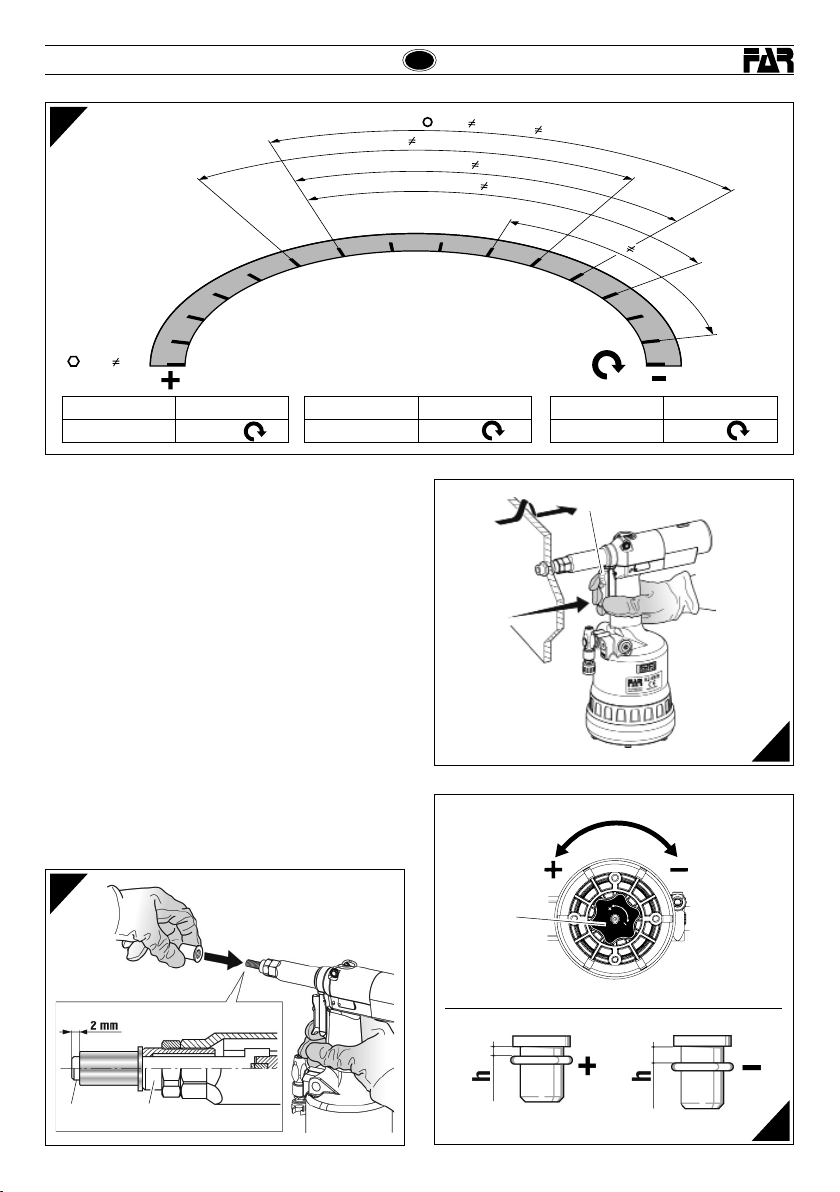
P r i m a d i u t i l i z z a r e l a r i v e t t a t r i c e e d o p o o g n i c a m b i o d i f o r m a t o
occo rre reg olare la c orsa in f unzion e delle di mension i, del tip o
di inserto e dello spessore del materiale da serrare. Prima di
compiere que sta opera zione ruot are il pomell o (M) second o
il senso della freccia, (+) per aumentare la corsa e (-) per
diminuirla. Considerando che all’aumentare della corsa rota zion e del pomel lo (M) - nel s enso ind icato d al simbol o (+),
la distanza “h” (pag. 7) d iminuisc e con con seguen te aumen to
dell’azione di serraggio. Per verificare se la corsa è regolata
correttamente controllare l’indicatore (N), confrontandolo
con i valori della tabella (fig. f3).
NOTA: Prima della posa in opera definitiva dell’inserto è
bene verificare il serraggio che questo opera sugli spessori
interessati, compiendo ulteriori regolazioni, come specificato
a pagina 10 (le regolazioni riportate sono puramente
indicative; è consigliabile consultare i dati tecnici degli
inserti utilizzati).
ATTENZIONE!!! La regolazione non corretta
della corsa della rivettatrice può causare il
cattivo serraggio degli inserti e la probabile
rottura del tirante!
ATTENZIONE!!! Le operazioni sopraelencate
devono essere eseguite con macchina non
alimentata. Per visualizzare la corsa modificata
(N) bisogna alimentare la macchina.
3
4
5
GRUPPO FRL
F
Q
• Per alimentare la macchina, spostare il cursore della valvola
ingresso aria (Q) verso l’alto.
• Per scaricare la macchina dall’aria e bloccare l’alimentazione,
spostare il cursore della valvola ingresso aria (Q) verso il basso, e
solo a questo punto, effettuare le varie operazioni di registrazione
della corsa.
6 Date 07-2016 Revisione - 08
f2
Page 7
KJ 45/S
KJ 45/S
I
f3
0
1
M
8
9
10
11
12
13
M12
1 ÷ 4
Corsa tirante max. Giri (M)
~ 8 mm 15
POSA IN OPERA DELL’INSERTO (fig. f4-f5-f6)
Verif icare che il gruppo t irante fil ettato (A) e testina (B) m ontato
sulla r ivet tatr ice sia ad eguat o alla misu ra dell’ inser to che si v uole
utilizzare. Regolare la corsa come riportato (fig. f2-f3).
Inser ire l’in ser to sul tir ante (A) e d e s e r c i t a r e s u d i e s s o u n a l e g g e r a
pressione come indicato in figura f4, in questo mod o l’inserto si
avvita automaticamente sul tirante filettato. Assicurarsi che la
testa dell’inserto vada in battuta con la testina (B) verificando
che il tirante (A) fuoriesca di 2mm dall’inserto.
In caso di ulteriore regolazione del tirante (A) procedere come
ripor tato a pag. 10.
E' possibile ora procedere alla messa in posa dell' inserto,
premendo il pulsante (D) (fig.f5) fino alla tirata completa dell'
inser to, pe r il disim pegno de l tira nte pre mere il pu lsan te (P) (fi g.f7)
Per una c orre tta p osa ed u n corre tto f unzio namen to dell a macc hina
è nece ssario ch e gli insert i utilizz ati siano a deguata mente puli ti.
Nota: Se necessario, in funzione del serraggio desiderato,
compiere ulteriori regolazioni della corsa della rivettatrice,
mediante la rotazione del pomello (M) (fig. f2-f3-f6).
Deformazione insufficiente = l’inserto potrebbe ruotare
all’interno dell’alloggiamento pregiudicandone l’utilizzo e la
resistenza.
Deformazione eccessiva = possibili danneggiamenti dell’inserto
e tirante (A) con probabili rotture di entrambi i componenti.
14
15
Corsa tirante Giri (M)
~ 0.4 mm 1
M
1
2
1
÷
7
/
M
6
0
.
5
÷
1
÷
6
M
8
0
.
8
÷
6
M
5
0
.
5
÷
7
6
6
5
M
4
0
.
3
÷
5
4
3
4
2
1
0
Corsa tirante min. Giri (M)
~ 2 mm 0
D
f5
f4
A
B
Revisione - 08 Date 07-2016
M
f6
7
Page 8

I
KJ 45/S
KJ 45/S
ANOMALIE DI FUNZIONAMENTO (fig. f7)
In tutti i casi in cui si verificano condizioni per le quali sia
necessario ottenere uno svitamento forzato del tirante filettato
dall'inserto, premere il pulsante (P).
ATTENZIONE! Eseguire questa operazione
trattenendo saldamente la rivettatrice in modo
da impedirle eventuali bruschi movimenti che
potrebbero danneggiare persone o cose.
f7
8 Date 07-2016 Revisione - 08
Page 9

KJ 45/S
KJ 45/S
CAMBIO DI FORMATO (fig. f8-f9 f10-f11)
La rivettatrice viene fornita con 6 coppie di tiranti filettati
(A), testine (B), trascinatori (R) e, solo per la serie di tiranti
da M4 a M6, di distanziali (S) (f8).
Per effettuare il cambio di formato procedere come segue:
• Svitare il cannotto porta testina (O) con una chiave
commerciale di mm 22 (f9).
• Togliere il tirante filettato, spingendolo e
contemporaneamente sollevandolo (f10).
• Dopo aver preparato il tirante filettato (A) della misura
desid erat a, dispo rre e sos tenere i c ompone nti come i n f11
ed eseguire il montaggio, assicurandosi che i particolari
siano correttamente in sede, facendo ruotare a mano il
tirante (f11).
ATTENZIONE!
• Nel componente (R) il lato da inserire nella testa tirante
è calamitato per evitarne la caduta accidentale nelle
operazioni di cambio formato.
• Avvitare il cannotto porta testina (O) con una chiave
commerciale di mm 22 e serrare correttamente.
ATTENZIONE!
Le operazioni sopraelencate devono essere
eseguite con macchina non alimentata.
I
ARB ARBS
22 mm
M8 - M12M4 ÷ M6
f10
f8
O
f9
Revisione - 08 Date 07-2016
f11
9
Page 10

I
KJ 45/S
KJ 45/S
REGOLAZIONE DEL GRUPPO TIRANTE TESTINA
(fig. f14-f15-f16)
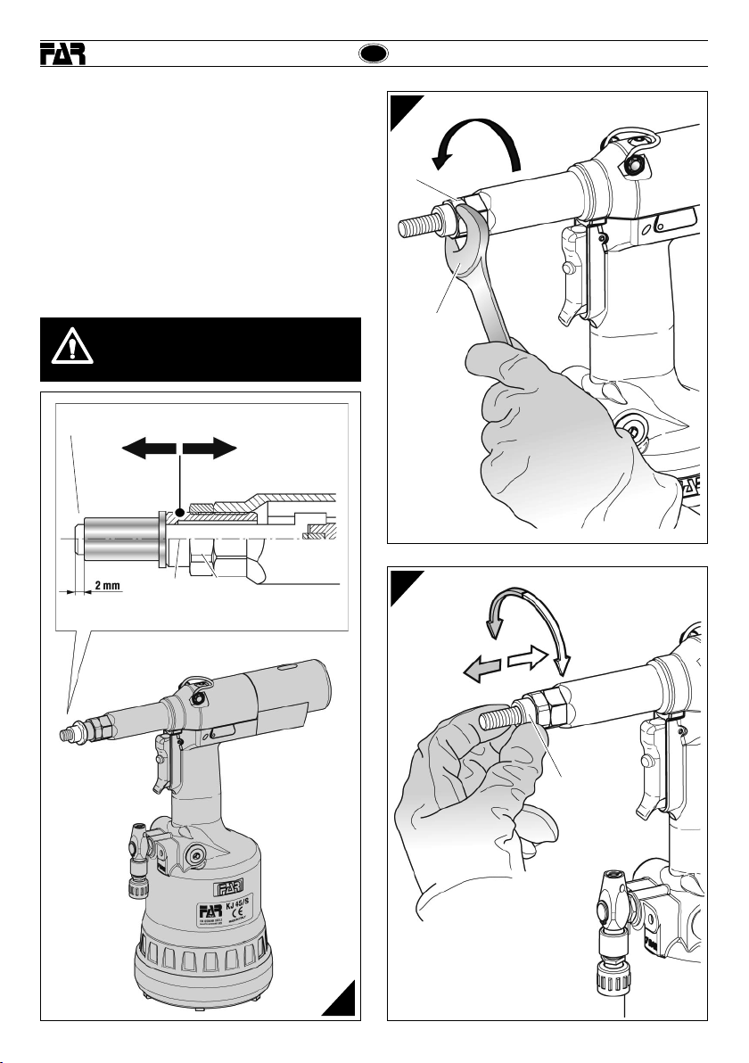
Al variare della lunghezza dell’inserto da serrare occorre
regolare la posizione della testina (B) rispetto al tirante
filettato (A).
Togliere l ’aliment azio ne dell’a ria comp ress a dalla ri vet tatr ice.
Avv itare ma nualment e un insert o della lungh ezza de siderat a
sul tirante filettato fino a che la testa dell’inserto vada in
battuta con la testina (B) della rivettatrice. La testina (B) è
regolata correttamente se il tirante filettato fuoriesce per
circa 2 mm d al l’ in se rt o a vv it a to s u d i e ss o. In ca so co nt ra ri o
sbloccare la ghiera (C) mediante una chiave commerciale di
mm 22 quindi avvitare o svitare la testina (B) fino a trovare
la giusta posizione, al termine bloccare la ghiera (C).
ATTENZIONE!
Le operazioni sopraelencate devono essere
eseguite con macchina non alimentata.
A
C
B
f15
C
22 mm
f16
B
f14
10 Date 07-2016 Revisione - 08
Page 11

KJ 45/S
KJ 45/S
RABBOCCO OLIO NEL CIRCUITO OLEODINAMICO (fig. f17-f18)
Il rabbocco dell’olio del circuito oleodinamico si rende
n e c e s s a r i o d o p o u n l u n g o p e r i o d o d i l a v o r o o q u a n d o s i a v v e r t e
un calo di corsa della rivettatrice. Procedere quindi come
segue : con rive tta trice no n aliment ata, r uotar e il pomell o (M)
verso il segno “+” sino al f inecorsa , posiziona re la macchin a
in verticale, rimuovere il tappo (I) servendosi della chiave a
brugola di mm 4 (in dotazione). Durante questa operazione
prestare la massima attenzione per evitare fuoriuscite di
olio. Avvitare nella sede del tappo (I) il contenitore olio (T)
(in dotazione) preventivamente riempito con olio idraulico
di HLP 32 cSt .
Mantenendo la rivettatr ice verticale, attivare l’alimentazione
dell’aria, premere il pulsante (D) facendo compiere
alla rivettatrice una serie di cicli fino a quando non sia
compl etamen te cessa ta l’emissi one di bolle d ’aria all’i nterno
del con tenitore ( T), quest a condizione sta a signi ficare che i l
rabbocco dell’olio è completato. A questo punto disattivare
l’alimentazione dell’aria e, con rivettarice sempre verticale,
svit are il contenitor e olio (T) e richiud erlo. Procedere quindi
alla chiusura del tappo (I) v erifi cando l’ integr ità del la ronde lla
ermetica e ripetere tutte le regolazioni per la posa in opera
dell’inserto riportate a pag. 6-7.
CAUTELA: È di estrema importanza attenersi alle istruzioni
sopra indicate ed effettuare le operazioni di rabbocco olio
muniti di guanti.
Nel caso di svuotamento completo del circuito idraulico,
recuperare tutto l’olio in un apposito contenitore e avvalersi
sucessivamente di una ditta autorizzata allo smaltimento
dei rifiuti.
ATTENZIONE!
Prima di scollegare il tubo dell’aria compressa
dalla rivettatrice accertarsi che quest’ultimo non
sia in pressione!
IMPORTANTE: Assicurarsi che il tappo di rabbocco
olio (I) venga serrato con una coppia pari a:
Min. 5 Nm ÷ Max. 8 Nm.
Si raccomanda l’uso di olio HLP 32 cSt o simili.
I
MANUTENZIONE
Manutenzione giornaliera
- Controllare che il tirante filettato non sia danneggiato.
- Controllare il sistema di alimentazione dell’aria compressa.
- Controllare che la corsa dell’attrezzo sia adatta per inserire
l’inserto selezionato (vedere le istruzioni relative alla
regolazione della corsa, riportate a pagina 6).
- Controllare che non vi siano perdite di aria o di olio. In tal
caso sostituire eventuali raccordi o guarnizioni danneggiate.
- Controllare che la pressione di alimentazione dell’aria
compressa sia di max 7 bar.
Manutenzione settimanale
- Controllare il livello dell’olio verificando la corsa della
rivettatrice. In caso di necessità r abboccare per prevenire
malfunzionamenti della rivettrice come riportato (fig. f18).
Revisione della rivettatrice
È consigliabile procedere ad una revisione completa della
rivettatrice dopo 600.000 cicli oppure ogni anno.
In qu es to ca so ri vo lg er si e sc lu si va me nt e a ce nt ri au to ri z za ti
dalla FAR S.r.l.
SMALTIMENTO DELLA RIVETTATRICE
f17
Revisione - 08 Date 07-2016
f18
Per lo smaltimento della rivet tatrice attenersi alle
prescrizioni imposte dalle leggi nazionali.
Dopo aver scollegato la macchina dall’impianto
pneumatico, procedere allo smontaggio dei vari
componenti suddividendoli in funzione della loro
tipologia: acciaio, alluminio, materiale plastico,
ecc.
Procedere quindi alla rottamazione nel rispetto
delle leggi vigenti.
11
Page 12

KJ 45/S
INSTRUCTIONS FOR USE I
INDEX
GUARANTEE ............................................................................. 12
SAFETY MEASURES AND REQUIREMENTS ............................. 12
TOOL IDENTIFICATION .............................................................13
GENERAL NOTES AND USE ...................................................... 13
MAIN COMPONENTS ................................................................ 13
TECHNICAL DATA ..................................................................... 13
AIR FEED ................................................................................... 14
PRELIMINARY OPERATIONS .................................................... 14
PLACING OF THE INSERT ......................................................... 15
WORKING PROBLEMS ............................................................. 16
CHANGE OF SIZE ..................................................................... 17
ADJUSTMENT OF TIE-ROD/HEAD UNIT ................................... 18
TOOPING UP THE OIL-DYNAMIC CIRCUIT ............................... 19
MAINTENANCE ........................................................................ 19
DISPOSAL OF THE RIVETING TOOL ......................................... 19
GUARANTEE
FAR riveting tools are covered by a 12-month warrant y. The
tool warranty period starts on the date of delivery to the
buyer, as specified in the relevant document. The warranty
covers the user/buyer provided that the tool is purchased
through an authorized dealer and only if it is used for the
purposes for which it was conceived. The warranty shall
not be valid if the tool is not used or maintained as specified
in the instruction and maintenance handbook. In the event
of defects or failures, FAR S.r.l. shall undertake solely to
repair and/or replace the components it judges to be faulty.
SAFETY MEASURES AND REQUIREMENTS
GB
• The tool can be carried and we suggest putting it into its box after
using.
• The tool needs a thorough six-monthly overhaul.
• Repairing and cleaning operations must be done when the tool
is not fed.
• A safety balancer is suggested when it is possible.
• If the A-weighted emission sound pressure level is more than
70 dB (A), you must use some hearing protections (anti-noise
headset, etc.).
• The workbench and the work surface must be always clean and
tidy. The untidy can cause damages to people.
• Do not allow unauthorized persons to use the working tools.
• Make you sure that the compressed air feeding hoses have the
correct size to be used.
• Do not carry the connected tool by pulling the hose. The hole
must be far from any heating sources or from cutting parts.
• Keep the tools in good conditions; do not remove either safety
parts or silencers.
• After repairing and/or adjusting, make sure you have already
removed the adjusting spanners.
• Before disconnecting the compressed air hose from the tool
make sure that there is no pressure in the hose.
• These instructions must be carefully followed.
KJ 45/S
ATTENTION! In case of strong impacts or accidental
falls the machine should be completely overhauled.
CAUTION!!!
All the operations must be done in conformity
with the safety requirements, in order to avoid
any consequence for your and other people
security and to allow the best tool work way.
• Read the instructions carefully before using the tool.
• For all maintenance and/or repairs please contact FAR s.r.l.
authorized service centers and use only original spare parts.
FAR s.r.l. may not be held liable for damages from defective parts
caused by failure to observe what mentioned above (EEC directive
85/374).
The list of the service centres is available on our website
http://www.far.bo.it ( Organization )
• The tool must be used only by expert workers.
• A protective visor and gloves must be put on when using the
tool.
• Use equipment recommended in the maintenance chapter to do
any maintenance and/or regulation of the tool.
• For topping up the oil, we suggest using only fluids in accordance
with the features specified in this working book.
• If any drop of oil touches your skin, you must wash with water
and alkaline soap.
12 Date 07-2016 Revisione - 08
Page 13

KJ 45/S
KJ 45/S
GB
TOOL IDENTIFICATION
The riveting tool KJ 45/S is identified from a marking
that shows company name and address of manufacturer,
desig nation of the tool, CE. Always refer to the information on
the riveting tool when requesting technical service.
Company name and
address
Designation of the tool
MAIN COMPONENTS
A) .........................................................................Threaded tie rod
B) .......................................................................................... Head
C) .............................................................Ring-nut clamping head
D) ...................................................................Control push-button
E) .......................................................Compressed air connection
F) ...............................................................Pressure control valve
G) ......................................................................Protection bottom
H) ....................................................................... Pneumatic motor
I) ................................................................................Oil tank plug
L) ...................................................................Balancer connection
M) ...............................................................Stroke-adjusting knob
N) ......................................................................... Stroke indicator
O) .................................................................... Tube carrying head
P) .....................................................................Unscrewing button
Q) ...................................................................... Air-entry valve
with M10 tie rod
*
Lot number
GENERAL NOTES AND USE
The tool can be employed only for blind rivet nuts M4÷M12.
The KJ 45/S/S hydropneumatic system assures more power
than t he pneuma tic sys tem use d for othe r models . That me ans
a reduction in the problems due to the wear and tear of the
components, therefore, there will be an increa se in reliability.
The technical solutions adopted reduce the dimensions and
the wei ght of the too l, which is ver y handy fo r these rea sons.
The po ssibilit ies of lea kage fr om the oil- dynamic s ystem, ar e
eliminated by some sealed gaskets, which solve this problem.
TECHNICAL DATA
• Working pressure ....................................................... 6 - 7 BAR
• Min. int. diam. of the compressed air
feeding hose ..................................................................... 8 mm
• Max free air consumption per cycle ................................
• Maximum force ......................................... 6,5 BAR - 27440 N
• Weight (with equipment for M10)................................2,860 Kg
• Working temperature ................................................... -5°/+50°
• Root mean square in total acceleration
frequency (Ac) to which
the arms are subjected ............................................. < 2.5
** nl = litres at 20°, pressure of 1 atmosphere
• A-weighted emission sound pressure level ................... 74 dBA
• Peak C-weighted instantaneous sound pressure .......<130 dBC
• A-weighted emission sound pressure ........................... 86 dBA
Revisione - 08 Date 07-2016
9 Nl**
m/s
13
2
Page 14

GB
KJ 45/S
KJ 45/S
AIR FEED (fig. f1)
The compressed air system must be provided with air
cleaners and condensation drains and must guarantee that
the air supplied to the feeder has a constant pressure of min
6 bars. The regulator must be set at a pressure of 6,5 bars.
Connect the machine to the main compressed air supply as
shown in the diagram (f1):
1) Cutoff cock (used during maintenance of the filter regulator
or of the lubricating unit).
2) Main supply inlet.
3) Main supply bleed.
4) Pressure regulator and filter (bleed daily).
5) Lubricating unit.
ATTENTION! The riveting tool is equipped with a
relief valve (F) starting when the compressed-air
pressure significantly exceeds 7 bar.
ATTENTION! If the relief valve (F) starts and the air
consequently escapes, we recommend to check if
the tool feed pressure corresponds to the pressure
value indicated under the technical data in this
handbook (page 13).
f1
3 m Max
1
2
PRELIMINARY OPERATIONS (fig. f2-f3)
Check that the threaded tie rod (A) and head (B) couple
assembled on the riveting tool is suitable to the size of the
insert to clamp; otherwise change the size (page
tie-rod (A)/head (B) unit assembled on this riveting tool,
corresponds to a M10 thread.
Befor e using t he rive ting too l and af ter each c hange o f size, th e
stroke should be adjusted according to the dimensions, type
of the insert and thickness of the material to clamp. Before
carrying out this operation rotate the knob (M) according
to the direction of the arrow, (+) for increasing the stroke
and (-) for decreasing it. Increasing the stroke - rotation of
knob (M) - in the direction indic ated with th e symbol (+), the
distance “h” (page 15) decreases increasing the clamping
acti on. To verif y that th e stroke i s corre ctly ad justed c heck the
indic ator (N) c omparin g it with t he value s of the ta ble (fig. f3).
NOTE: Befo re the def initiv e placing o f the inser t, its cl amping
on the thicknesses involved should be checked, carrying
out other adjustments, as shown at page 18 (the specified
adjustments are just an indication, it is advisable to see the
technical data of the inserts used).
ATTENTION! The incorrect adjustment of the
riveting tool can cause a bad clamping of the
inserts and a possible break of the tie rod!
ATTENTION! The above-mentioned operations
must be done when the tool is not fed. For
visualizing the changed stroke (N) the tool
must be fed.
17). The
3
4
5
FRL UNIT
F
Q
• Move up the slider of the air-entry valve (Q) to feed the tool.
• Before regulating the stroke, discharge the tool by the air and stop
the feeding, moving down the slider of the air-entry valve (Q).
14 Date 07-2016 Revisione - 08
f2
Page 15

KJ 45/S
KJ 45/S
GB
f3
1
M
8
9
10
11
12
13
M12
1 ÷ 4
Tie rod max. stroke Revolutions (M)
~ 8 mm 15
PLACING OF THE INSERT (fig. f4-f5-f6)
Check that the threaded tie rod (A) and head (B) couple
assembled on the riveting tool is suitable to the size of the
insert to be used.
Adjust the stroke as indicated (fig. f2-f3).
Introduce the insert on the tie rod (A) and push sligh tly on it
as indicated in figure f4, so as t o make it cla mp automat ically
on the threaded tie rod. Make sure that the insert head touches
the head (B) checking that the tie rod (A) comes ou t of 2mm
from the insert.
In case of further adjustments of the tie rod (A) follow the
instructions of page 18.
It is now possible to place the insert pushing the button (D)
(fig.f5) until the insert is completely pulled, and push the
button (P) to release the tie rod (fig.f7).
For a correct placing and right working of the machine, the
inserts to be used should be properly cleaned.
Note: According to the desired clamping, carry out other
adjustments of the riveting tool stroke, rotating the knob
(M) (fig. f2-f3-f6), if necessary.
Insuf cien t deformation = the insert could rot ate inside the
housing compromising its use and resistance.
Excessive deformation = possible damages of the insert
and tie rod (A) with eventual breaks of both components.
14
15
Tie rod stroke Revolutions (M)
~ 0.4 mm 1
M
1
2
1
÷
7
/
M
6
0
.
5
÷
1
÷
0
6
M
8
0
.
8
÷
6
M
5
0
.
5
÷
7
6
6
5
M
4
0
.
3
÷
5
4
3
4
2
1
0
Tie rod min. stroke Revolutions (M)
~ 2 mm 0
D
f5
f4
BA
Revisione - 08 Date 07-2016
M
f6
15
Page 16

GB
KJ 45/S
KJ 45/S
WORKING PROBLEMS (fig. f7)
Any time it is necessary to unscrew forcedly the threaded
tie rod from the insert, push the button (P).
ATTENTION! Carry out this operation keeping
the riveting tool firmly in order to avoid sharp
movements which could damage people or
things.
f7
16 Date 07-2016 Revisione - 08
Page 17

KJ 45/S
KJ 45/S
CHANGE OF SIZE (fig. f8-f9-f10-f11)
T he ri v et i ng to ol i s s up pl i ed wi t h 6 pair s of threaded tie-rods
(A), heads (B), entreiners (R) and, spacers (S) only for tierods from M4 to M6 (f8).
To change the size make as follows:
• Unscr ew the con e-ca rryi ng head (O) by a 22 mm standard
spanner (f9).
• Extract the threaded tie-rod, pushing and lifting it at the
same time (f10).
• After preparing the threaded tie-rod (A) of the size you
need, arrange and keep the c omponents as shown in f11
and as semble. Be su re that the c omponent s are corr ectly
placed, rotating the tie-rod by hand (f11).
ATTENTION!
• The side of the component (R) to be entered in the head
of the tie-rod is provided of a magnet to avoid accident al
fall during the operations of change of size.
• Screw the cone carrying heads (O) by a 22 mm standard
spanner and clamp correctly.
ATTENTION!
Disconnect the machine before carrying out the
above-mentioned operations.
M8 - M12M4 ÷ M6
ARB ARBS
GB
f10
f8
O
22 mm
f9
Revisione - 08 Date 07-2016
f11
17
Page 18

GB
KJ 45/S
KJ 45/S
TIE-ROD/HEAD UNIT ADJUSTMENT (fig. f14-f15-f16)
Changing the length of the insert to clamp, the position of
the head (B) compared to the threaded tie rod (A) should
be adjusted.
Disconnect the compressed air feeding from the tool.
Screw an insert of the desired length on the threaded tie
rod manually until the insert head touches the riveting tool
head (B). The head is adjusted correctly if the threaded tie
rod comes out of the insert screwed on it of about 2 mm.
Otherwise unblock the ring nut (C) with a 22 mm standard
spanner then screw or unscrew the head (B) up to the right
position, and block the ring nut (C).
ATTENTION!
Disconnect the machine before carrying out the
above-mentioned operations.
A
C
B
f15
C
22 mm
f16
B
f14
18 Date 07-2016 Revisione - 08
Page 19

KJ 45/S
KJ 45/S
TOPPING UP THE OIL-DYNAMIC CIRCUIT (fig. f17-f18)
The oil -dyn amic cir cuit sho uld be topp ed up af ter a long p eriod
of work or when there is a power loss of the riveting tool.
Put the riveting tool (not fed) in a vertical position rotating
the knob (M) towards the sign “+” up to the end of stroke,
and remove the plug (I) by means of a 4 mm Allen wrench
(equippe d). During this operation check the oil level in order
to avoid any overflowing. Then pour the oil HLP 32 cSt into
the oil container (T) (equipped) which shall be screwed to
its seat on the plug (I).
While k eeping t he rive ting too l in ver tical p ositio n and st artin g
air feeding, push the button (D) and make the riveting tool
carry out some cycles until air bubbles inside the container
stop coming out. This condition indicates that the topping
up of the oil has been fully achieved. At this point stop the
air feeding and while keeping the riveting tool in a vertical
position, unscrew and close the oil container (T) and the
plug (I) checking the soundness of the hermetic washer and
repeat all the adjus tments for placing the insert as indic ated
at page 14-15.
ATTENTION: It is very important to follow the above-
ment ioned ins tructio ns and use gl oves durin g oil topping u p.
If you need to empty completely the hydraulic circuit, you
must pu t the oil in a su itabl e conta iner and c ontac t a compan y
authorized to dispose of wastes.
ATTENTION!
Before disconnecting the compressed air hose,
make sure that it is not under pressure!
ATTENTION: Make sure that the oil filler cap ( I )
is tightened at a torque corresponding to Min. 5
Nm ÷ Max. 8 Nm.
We recommend to use oil HLP 32 cSt or similars.
GB
f18
MAINTENANCE
Daily maintenance
- Check that the threaded tie rod is not damaged.
- Check the supply system of the compressed air.
- Chec k that the s troke of the t ool is suit able for the s electe d
inser t to cla mp (see the p ert aining i nstru ction s for adjus ting
the stroke, indicated at page 14).
- Check that there are neither air nor oil leakages. In this
case replace possible damaged connectors or seals.
- Check that the supply pressure of the compressed air does
not exceed 7 bar.
Weekly maintenance
- Ch eck the oi l level co ntroll ing the st roke of th e rivet ing tool.
If necessary fill up for preventing failures of the riveting
tool as indicated (fig. f18).
Overhaul of the riveting tool
It is adv isable t o carry ou t a complet e overhaul o f the rive ting
tool after 600,000 cycles or ever y year.
In this case apply only to centres authorized by FAR S.r.l.
DISPOSAL OF THE RIVETING TOOL
f17
Revisione - 08 Date 07-2016
Follow the prescriptions of the national laws for
disposing of the riveting tool.
After disconnecting the tool from the pneumatic
syst em, disa ssembl e and split a ll the comp onent s
accor ding to th e materi al: stee l, alumini um, plas tic
material, etc.
Then pr oceed t o scrap t he mater ials in a ccorda nce
with current laws.
19
Page 20

KJ 45/S
MODE D’EMPLOI I
INDEX
GARANTIE ................................................................................. 20
INSTRUCTIONS ET MESURES DE SECURITE ........................... 20
IDENTIFICATION DE L’OUTIL DE POSE ..................................... 21
CARACTERISTIQUES ET EMPLOI ............................................. 21
PARTIES PRINCIPALES ............................................................ 21
CARACTERISTIQUES TECHNIQUES .......................................... 21
ALIMENTATION EN AIR ............................................................. 22
OPERATIONS PRELIMINAIRES ................................................. 22
POSE DE L’INSERT.................................................................... 23
ANOMALIES DE FONCTIONNEMENT ........................................ 24
CHANGEMENT DE FORMAT ......................................................25
RÉGLAGE DU GROUPE TIRANT ET ENCLUME .......................... 26
REMPLISSAGE DE L’HUILE DU CIRCUIT HYDRAULIQUE ......... 27
ENTRETIEN ............................................................................... 27
ELIMINATION DE LA RIVETEUSE .............................................. 27
GARANTIE
Les riveteuses FAR sont sous garantie pendant 12 mois. La
période de garantie de l'outil commence à partir du moment
où il est avéré que son acquéreur en prend possession. La
garantie couvre l'utilisateur/acquéreur quand l'outil est acheté
chez un revendeur agréé et uniquement quand il est utilisé
aux fins pour lesquelles il a été conçu. La garantie n'est pas
valable si l'outil n'est pas utilisé et s'il n'est pas soumis à
l'entretien tel qu'il e st spécifi é dans le manue l d'utilisation et
d'entretien. En cas de défauts ou de pannes, la société FAR
S.r.l. s'engage uniqu ement à répar er et/ou à remplacer, à sa
seule discrétion, les composants jugés défectueux.
INSTRUCTIONS ET MESURES DE SECURITE
t
ATTENTION!!!
Le non respect des instructions suivantes peut
avoir des conséquences désagréables pour
vous-mêmes et pour l’intégrité d’autrui.
F
Pour l’entretien et/ou réglage de l’outil de pose, se servir des
•
équipements indiqués dans le chapitre “ENTRETIEN”.
KJ 45/S
• Pour le remplissage de l’huile, il faut utiliser les fluides indiqués
dans ce dossier.
• En cas de fuites imprévues de huile (au contact de la peau), il
faut se laver soigneusement avec de l’eau et du savon alcalin.
• L’outil de pose peut être transporté à la main et il doit être remis
dans sa boîte après l’usage.
• Pour obtenir un bon fonctionnement de l’outil, nous vous
suggérons de le réviser tous les six mois.
• Les interventions de réparations et de nettoyages de l’outil doivent
se faire machine non alimenté en air.
• Si possible, il faudrait utiliser des équilibreurs de sécurité.
• En cas d’exposition quotidienne où le niveau de pression soit
supérieur à la limite de sécurité 70 dB (A), l’on doit assurer
la protection de l’ouïe (casque antibruit, réduction du temps
d’exposition quotidienne, etc).
• La table et le poste de travail doivent être toujours propres et
rangés. Le désordre peut causer des dommages aux personnes.
• Les personnes non authorisées ne peuvent pas se servir des
outils de pose.
• Il faut s’assurer que les tuyaux d’alimentation de l’air comprimé
soient appropriés (conformes) à l’utilisation prévue.
• Ne pas transporter l’outil de pose quand il est connecté à
l’alimentation. Le tuyau doit se trouver toujours loin de sources
de chaleur ou d’objets tranchants.
• Les outils de pose doivent être toujours en bon état. Ne pas
enlever les protections et le silencieux de l’outil.
• Après la réparation et/ou réglage, il faut s’assurer d’avoir enlever
les clés de réglage.
• Avant de débrancher le tuyau d’alimentation d’air comprimé de
l’outil, il faut s’assurer qu’il ne soit pas sous pression.
• Suivre scrupuleusement ces instructions.
ATTENTION! En cas de choc violent ou de chute
accidentelle, procéder à la révision complète de la machine.
• Lisez avec soin la notice avant l’usage.
• Pour les opérations d’entretien et/ou réparations, adressez-vous
aux centres de service après-vente autorisés de
n’utilisez que des
décline toute responsabilité pour les dommages dus à des
pièces défectueuses qui interviendraient suite au non-respect
de la notice ci-dessus (Directive CEE 85/374).
pièces détachées originales. FAR s.r.l.
FAR s.r.l. et
La liste des centres d’assistance est disponible sur notre site
internet http://www.far.bo.it ( Organisation )
L’outil de pose doit être utilisé par le personnel spécialisé.
•
• Pendant l’utilisation de l’outil utiliser des gants et des lunettes
de protections ou une visière
20 Date 07-2016 Revisione - 08
Page 21

KJ 45/S
KJ 45/S
F
IDENTIFICATION DE L’OUTIL DE POSE
L’o u t il KJ 45/S est identifié par un marquage indiquant
raison sociale et adresse du fabricant, désignation de l’outil
de pose, marquage CE.
En cas de recours au service après-vente, il faut toujours se
référer aux données indiquées sur la riveteuse.
Raison sociale et adresse
Designation de l’outil
de pose
PARTIES PRINCIPALES
A) .................................................................................Tirant fileté
B) ............................................................................................ Tête
C) ................................................................Bague de blocage tête
D) ................................................................Bouton de commande
E) ......................................................Raccordement air comprimé
F) ..................................................................Limiteur de pression
G) .....................................................................Base de protection
H) ..................................................................Moteur pneumatique
I) ...........................................................Bouchon réservoir d’huile
L) .................................................................... Fixation équilibreur
M) .................................................... Pommeau de réglage course
N) ..................................................................Indicateur de course
O) ............................................................................... Support tête
P) ..................................................................Bouton de dévissage
Q) ....................................................................Valve d’arrivée d’air
avec tirant pour M10
*
Numéro de lot
CARACTERISTIQUES TECHNIQUES
CARACTERISTIQUES ET EMPLOI
L’outil peut être utilisé seulement pour les inserts filetés
M4÷M12.
Le système oléopneumatique de l’outil KJ 45/S permet
d’obtenir un puissance supérieure par rapport au système
pneumatique traditionnel.Cela signifie une réduction
des problèmes provoqués par l’usure des composants,
donc, une plus grande longevité. Les solutions techniques
adoptées réduisent les dimensions et le poids du pistolet en
la rendant très maniable. Les risques de fuites du système
oléodynamique sont éliminés par l’utilisation de joints à
haute résistance.
• Pression de service .................................................... 6 - 7 BAR
• Diamètre interne minimum tuyau d’alimentation
air comprimé .................................................................... 8 mm
• Consommation air max. par cycle ..................................
• Force maximum .......................................6,5 BAR - 27440 N
• Poids (avec équipement pour M10) ............................. 2,860 kg
• Température d’utilisation ............................................-5°/+50°C
• Valeur quadratique moyenne pondérée en
fréquence d’accélération totale (Ac) à laquelle
sont soumis les membres supérieurs .......................< 2,5
** nl = litre à 20°C, pression atmosphérique
• Pression acoustique de l’émission pondéré (A) ............74 dBA
• Pression acoustique instantanée pondéré (C) ..........<130 dBC
• Puissance acoustique pondérée (A) .............................. 86 dBA
Revisione - 08 Date 07-2016
9 Nl**
m/s
21
2
Page 22

F
KJ 45/S
KJ 45/S
ALIMENTATION EN AIR (fig. f1)
L e c i r c u i t d ’ a l i m e n t a t i o n d o i t ê t r e d o t é d e d i s p o s i t i f s a s s u r a n t
le filtrage de l’air et l’évacuation des condensations, il
doit garantir une pression constante d’alimentation de
l’alimentateur de min. 6 bars. Le régulateur doit être placé
sur une pression de 6,5 bars.
Racc order la m achine a u circui t d’alimen tati on d’air com primé
principal en suivant les indications du schéma (f1).
1) Robinet d’arrêt (à utiliser pour les opérations d’entretien du
régulateur filtre ou de l’unité de lubrification).
2) Point d’arrivée de l’alimentation principale.
3) Point de purge pour l’alimentation principale.
4) Régulateur de pression et filtre (purger chaque jour).
5) Lubrificateur.
ATTENTION! La riveteuse est équipée d’une valve
limitatrice (F) qui intervient en cas de pression
de l’air comprimé nettement supérieure à 7 bars.
ATTENTION! Si la valve limitatrice (F) intervient
et que l’air sort, nous recommandons de vérifier
que la pression d’alimentation de la riveteuse
corresponde à la valeur de pression indiquée
dans les caractéristiques techniques de ce
manuel (pag. 21).
f1
3 m Max
1
2
OPERATIONS PRELIMINAIRES (fig. f2-f3)
S’assurer que le groupe, tirant fileté (A) et tête (B), monté
sur la riveteuse est adapté à la taille de l’insert à sertir; si tel
n’est pas le cas, procéder au changement de format (page
2 5) . Le g ro u p e t i r an t f il e t é ( A) et enc lume (B) mont é d’origine
sur l’outil est un filetage M10.
Avant d’utiliser la riveteuse et après chaque changement
de format, il est nécessaire de régler la course en fonction
des dimensions, du format de l’insert et de l’épaisseur du
matér iau à ser tir. Avant d e procé der à cet te opér ation, t ourner
le pomm eau (M) da n s l e s en s de l a f l èc h e (+) pour aug menter
la course et (-) pour la diminuer. En tenant compte du fait
que l’augmentation de la course - rotation du pommeau (M)
- dans le sens indiqué par le symbole (+) réduit la distance
“h” (page 23), ce qui a pour effet d’augmenter l’action de
serrage. Pour s’assurer que la course est correctement
réglée, contrôler l’indicateur (N) en faisant référence aux
valeurs du tableau (fig. f3).
NOTE: Avant de procéder à la pose définitive de l’insert, il
est re commandé de c ontrôler le serr age appliqué a ux pièces
concernées, en effectuant de nouveaux réglages comme
indiqué page 26 (les réglages mentionnés sont purement
indicatifs; il est recommandé de consulter les données
techniques des inserts utilisés).
ATTENTION! Le mauvais réglage de la course
de la riveteuse peut entraîner le mauvais serrage
des inserts et la rupture du tirant!
ATTENTION! Les opérations ci-dessus doivent
être effectuées alors que la machine n’est pas
alimentée. Pour visualiser la course modifiée
(N), il est nécessaire d’alimenter la machine.
3
4
5
GROUPE FRL
F
Q
• Pour alimenter l’outil en air, déplacer le curseur de la valve d’arrivée
d’air (Q) vers le haut.
• Pour décharger l’air de l’outil et bloquer l’alimentation, déplacer
le curseur de la valve d’arrivée d’air (Q) vers le bas, et seulement
après cela effectuer les diverses opérations de réglage de course.
22 Date 07-2016 Revisione - 08
f2
Page 23

KJ 45/S
KJ 45/S
F
f3
0
1
M
8
9
10
11
12
13
M12
1 ÷ 4
Course tirant max. Tours (M)
~ 8 mm 15
14
15
Course tirant Tours (M)
~ 0.4 mm 1
POSE DE L’INSERT (fig. f4-f5-f6)
S’assurer que le groupe tirant fileté (A) et tête (B) monté sur la
riveteuse est adapté à la taille de l’insert à utiliser.
Régler la course comme indiqué (fig. f2-f3).
I n t r o du i r e l ’ i n s e r t su r l e t i r a n t (A) et exe rcer sur c elui-c i une légè re
pression comme indiqué sur la figure f4, de sorte que l’inser t se
viss e automat iquement s ur le tiran t fileté. S ’assurer que l a tête de
l’insert est en butée contre la tête (B) en s’assurant que le tirant
(A) dépasse de l’insert de 2 mm.
En cas de nouveau réglage du tirant (A), procéder comme
indiqué page 26.
Il est à présent possible de procéder à la pose de l’insert, en
appuyant sur le bouton (D) (fig.f5)
jusqu’au sertissage complet de l’insert, pour le dégagement du
tirant pressez sur le bouton (P) (fig. f7)
P o u r a s s u r e r c o r r e c t em en t l a p o s e e t d o n c l e b o n f o n c t i o n n e m e n t
de la machine, il est nécessaire que les inserts utilisés soient
parfaitement propres.
Note: Au besoin, en fonction du serrage voulu, effectuer de
nouveaux réglages de la course de la riveteuse, par rotation du
pommeau (M) (fig.
f2-f3-f6).
Déformation insuf sante = l’insert pourrait tourner à l’intérieur
d u l o ge m e nt e t c o mp r o me t t r e l e fo n c ti o n ne m e nt e t l a ré s i st a n c e.
Déformat ion excessive = possibles dommages de l’inser t et du
tirant (A) et probable rupture des deux composants.
f4
M
1
2
1
÷
7
/
M
6
0
.
5
÷
1
÷
6
M
8
0
.
8
÷
6
M
5
0
.
5
÷
7
6
6
5
M
4
0
.
3
÷
5
4
3
4
2
1
0
Course tirant min. Tours (M)
~ 2 mm 0
D
f5
M
BA
Revisione - 08 Date 07-2016
f6
23
Page 24

F
KJ 45/S
KJ 45/S
ANOMALIES DE FONCTIONNEMENT (fig. f7)
Lors qu’il est n écess aire d’obt enir un dév issa ge forcé d u tiran t
fileté de l’insert, il faut appuyer sur le bouton (P)
ATTENTION! Effectuer cette opération en
tenant fermement la riveteuse de façon à
éviter les mouvements brusques susceptibles
de provoquer des dommages physiques et
matériels.
f7
24 Date 07-2016 Revisione - 08
Page 25

KJ 45/S
KJ 45/S
CHANGEMENT DE FORMAT (fig. f8-f9 f10-f11)
L’outil e st fourn i avec 6 ens emble ti rants f ileté s (A), enclu mes
(B) et réduction hexagonale (R) et avec des entretoises (S)
seulement pour les tirants de M4 à M6 (f8)
P o u r e f f e c t u e r l e c h a n g e m e n t d e f o r m a t , p r o c é d e r c o m m e s u i t :
• Dévi sser le sup port po rte tê te (O) avec une c lé commer cial
de 22 mm (f9).
• Pour enlever le tirant fileté, pousser et soulever le tirant
(f10).
• Après avoir préparé le tir ant (A) de la dimension désirée,
soutenir les composants comme indiquer dans le f11 et
exécuter la mise en place, s’assurer que l’ensemble des
composants soit correctement centré en faisant tourner
le tirant (f11).
ATTENTION!
• Pour les réductions hexagonales (R) l e c o t é i n s é r é d a n s l e
tirant est aimanté pour év iter sa chut e lors de l’opération
de changement de format.
• Visser le support porte tête (O) avec une clé commercial
de 22 mm et serrez correctement.
ATTENTION!
Les opérations ci-dessus doivent être effectuées
alors que la machine n’est pas alimentée.
M8 - M12M4 ÷ M6
ARB ARBS
F
f10
f8
O
22 mm
f9
Revisione - 08 Date 07-2016
f11
25
Page 26
F
KJ 45/S
KJ 45/S
RÉGLAGE DU GROUPE TIRANT ET ENCLUME (fig. f14f15-f16)
En cas de variation de la longueur de l’insert à serrer, il est
nécessaire de régler la position de la tête (B) par rapport au
tirant fileté (A).
Couper l’alimentation d’air comprimer de l’outil.
Visser manuellement un insert de la longueur voulue sur
le tirant fileté jusqu’à ce que la tête de l’insert soit en butée
contre la tête (B) de la riveteuse. La tête est correctement
réglée si le tirant dépasse d’environ 2 mm l’insert vissé sur
celui -ci. Si tel n’est p as le cas, dé bloquer la bague (C) à l’aid e
d’une clé commerciale de 22 mm puis visser ou dévisser la
tête (B) jusqu’à c e que soit ob tenue la bo nne posit ion, ensui te
bloquer la bague (C).
ATTENTION!
Les opérations ci-dessus doivent être effectuées
alors que la machine n’est pas alimentée.
A
C
B
f15
C
22 mm
f16
B
f14
26 Date 07-2016 Revisione - 08
Page 27

KJ 45/S
KJ 45/S
REMPLISSAGE DE L’HUILE DU CIRCUIT HYDRAULIQUE
(fig. f17-f18)
Le rav itail lement d ’huile du c ircuit h ydrauli que est né cessa ire
après une longue période de fonctionnement ou en cas de
diminution de la course de la riveteuse. Procéder comme
suit: sur la riveteuse non alimentée, tourner le pommeau
(M) dans le sens du signe “+” jusqu’en bout de course,
positionner la machine à la verticale, retirer le bouchon
(I) à l’aide d’une clé Allen de 4 mm (fournie). Durant cette
opération, faire très attention pour éviter le renversement
d’huile. Visser le récipient d’huile (T) (fourni) préalablement
rempli d’huile hydraulique HLP 3 2 cSt sur le b ouchon ( I). Tout
en maintenant la riveteuse à la verticale, activer l’alimentation
d’air, appuyer sur le bouton (D) en fai sant ef fectuer qu elques
cycles à la riveteuse, jusqu’à ce qu’ait cessé le dégagement
de bulles d’air dans le réservoir (T), cette condition indique
que le ravitaillement de l’huile est terminé. Ensuite, couper
l’alime ntat ion d’air et , toujour s avec la r iveteu se à la ver tica le,
dévisser le récipient d’huile (T) et le refermer. Procéder ensuite
à la remise en place du bouchon (I) en contrôlant l’état de la
rondelle hermétique et effectuer tous les réglages de pose
de l’insert décrits page 22-23.
RECOMMANDATION: Il e s t t r è s i m p o r t a n t d e v e i l l e r a u r e s p e c t
des instructions ci-dessus et d’effectuer le ravitaillement
d’huile muni de gants.
En cas d e vidang e complèt e du circui t hydraul ique, récu pérer
l’huile dans un récipient et la remettre à un centre agréé de
collecte des déchets.
ATTENTION!
Avant de débrancher le tuyau d’air comprimé de la
riveteuse, s’assurer qu’il n’est plus sous pression!
IMPORTANT: S’assurer que le bouchon de
remplissage d’huile (I) soit vissé avec couple de
Min. 5 Nm ÷ Max. 8 Nm.
Nous recommandons l'utilisation d'huile
HLP 32 cSt ou similaires.
F
ENTRETIEN
Entretien quotidien
- s’assurer que le tirant fileté n’est pas endommagé.
- contrôler le système d’alimentation d’air comprimé.
- s’assurer que la course de l’outil est adapté à la pose de
l’insert sélectionné (voir les instructions relatives au réglage
de la course, page 22).
- s’assurer de l’absence de fuites d’air ou d’huile; en présence
de fuites changer les raccords ou les garnitures endommagés.
- s’assurer que la pression d’alimentation d’air ne dépasse pas
7 bars.
Entretien hebdomadaire
- contrôler le niveau d’huile en vérifiant la course de la riveteuse;
au besoin ravitailler pour prévenir le mauvais fonctionnement
de la riveteuse, en procédant comme indiqué (fig. f18).
Révision de la riveteuse
Il est recommandé de procéder à une révision complète de
la riveteuse au bout de 600.000 cycles ou chaque année.
A cet effet, s’adresser exclusivement à un centre d’assistance
agréé FAR S.r.l.
ELIMINATION DE LA RIVETEUSE
f17
Revisione - 08 Date 07-2016
f18
Pour l’élimination de la riveteuse, veiller au respect
des dispositions légales en vigueur dans le pays où
l’élimination s’effectue.
Aprè s avoir déb ranch é la machi ne de l’alim entat ion
pneumatique, procéder au démontage des
différents composants en fonction de la nature
des matériaux : acier, aluminium, matières
plastiques, etc…
Procéder à la démolition dans le respect de la
réglementation en vigueur.
27
Page 28

D
KJ 45/S
KJ 45/S
BEDIENUNGSANLEITUNGI
INHALTSVERZEICHNIS
GARANTIE ................................................................................. 28
SICHERHEITSMASSNAHMEN UND ANWEISUNGEN ................ 28
WERKZEUGIDENTIFIZIERUNG .................................................. 29
ALLGEMEINES UND ANWENDUNGSBEREICH ..........................29
HAUPTTEILE ............................................................................. 29
TECHNISCHE DATEN................................................................. 29
LUFTZUFÜHRUNG .................................................................... 30
EINLEITENDE MASSNAHMEN................................................... 30
SETZVORGANG ......................................................................... 31
BETRIEBSSTÖRUNGEN ............................................................ 32
DIMENSIONSWECHSEL ............................................................ 33
EINSTELLUNG VON GEWINDEDORN/MUNDSTÜCK ................. 34
NACHFÜLLEN VON ÖL IN DEM ÖLDYNAMISCHEN KREIS........ 35
WARTUNG ................................................................................ 35
ENTSORGUNG DER NIETMASCHINE ........................................ 35
GARANTIE
Auf die Nietwerkzeuge von FAR wird eine Garantie von 12
Monaten gewährt. Der Garantiezeitraum beginnt in dem
Momen t, in dem de r Käufe r das Ger ät nach weisli ch in Empf ang
genommen hat. Die Garantie ist nur gültig, wenn das Gerät
bei einem Vertragshändler erworben und ausschließlich zu
den Zwe cken ver wendet w ird, für die e s konzipi ert wur de. Die
Garantie wird ungültig, wenn da s Gerät nicht in Einklang mit
den Anweisungen in der Betriebs- und Wartungsanleitung
verw endet u nd gewar tet w ird. Die F irma FAR s.r.l. verpflichtet
einzig zur Reparatur bzw. zum Austausch, nach ihrem
ausschließlichen Ermessen, der Komponenten, die für
mangelhaft befunden werden.
SICHERHEITSMASSNAHMEN UND ANWEISUNGEN
ACHTUNG!!!
Alle Arbeiten müssen in Übereinstimmung
mit den Sicherheitsvorschriften durchgeführt
werden, um die eigene Sicherheit und die
anderer Personen zu gewährleisten und die
beste zu erreichen.
• Verwenden Sie nur Ausrüstungen die in der Betriebsanleitung
empfohlen sind, wenn Sie am Werkzeug Instandsetzungen und
Regulierungen durchführen.
• Beim Ölwechsel verwenden Sie nur Öle die den empfohlenen Ölen
dieser Anleitung entsprechen.
• Falls Sie Öl auf die Haut bekommen, waschen Sie die mit Wasser
und Alkaliseife ab.
• Wir empfehlen das Werkzeug nach Gebrauch in den Koffer zu
geben, in der es auch transportiert werden kann.
• Das Werkzeug soll alle sechs Monate gründlich überholt werden.
• Bei Reparatur und Reinigung des Werkzeuges ist das Gerät immer
vom Druckluftnetz zu trennen.
• Wenn notwendig verwenden Sie einen Sicherheits-Balancer.
• Falls das Personal täglich einem A-bewerteten
Emissionsschalldruckpegel über die gesetzliche Grenze von 70
dB (A) ausgesetzt ist, muss immer ein Ohrenschutz getragen
werden (wie Gehörschutzkapseln oder -pfropfen, Verkürzung
des täglichen Aufenthalts im Lärmbereich usw.)
• Die Werkbank und/oder Arbeitsfläche sollen immer rein sein; die
Unordnung kann Personenschaden verursachen.
• Werkzeuge dürfen durch Unbefugte nicht betrieben werden.
• Versichern Sie sich, daß der Druckluftschlauch in der richtigen
Dimension ist.
• Nehmen Sie das angeschlossene Werkzeug nie am
Druckluftschlauch.
Das gesamte Werkzeug soll fern von Hitze und schneidenden
Teilen gehalten werden.
• Halten Sie das Werkzeug sauber und in gutem Zustand und
nehmen Sie weder Schutzvorrichtungen noch Schalldämpfer weg.
• Nach Reparatur und/oder Einstellung vergewissern Sie sich, daß
die Dienst- oder Einstellschlüssel entfernt wurden.
• Bevor Sie den Druckluftschlauch vom Werkzeug abschalten,
vergewissern Sie sich, dass dieser drucklos ist.
• Diese Anweisungen müssen sorgfältig beachtet werden.
ACHTUNG! Bei harten Stößen oder versehentlichen Stürzen
ist die Generalüberholung der Maschine durchzuführen.
• Die Anleitung vor Gebrauch des Geräts aufmerksam lesen.
• Die Wartungs- und/oder Reparaturarbeiten von den autorisierten
Kundendienststellen von FAR s.r.l. ausführen lassen und
ausschließlich Originalersatzteile verwenden. Die Firma FAR s.r.l.
haftet nicht für durch defekte Teile verursachte Schäden, sofern
diese auf die Mißachtung der o.g. Vorschrift zurückzuführen sind
(Richtlinie 85/374/EWG).
Die Liste der Reparaturservices ist verfügbar unter unserer
Webseite http://www.far.bo.it ( Organisation )
• Das Werkzeug darf nur von Facharbeitern benütz werden.
• Bei Gebrauch des Werkzeuges sind Schutzbrille und Handschuhe
zu verwenden.
28 Date 07-2016 Revisione - 08
Page 29

KJ 45/S
KJ 45/S
D
WERKZEUGIDENTIFIZIERUNG
Das Werkzeug KJ 45/S ist durch eine Markierung
gekennzeichnet, die den Firmenname und Adresse des
Herstellers, Angabe des Werkzeugs, CE Marke zeigt.
Bei Anfragen an den technischen Kundendienst stets die auf
dem Nietwerkzeug genannten Daten angeben.
Firmenname und adresse Angabe des werkzeugs
HAUPTTEILE
A) ..............................................................................Gewindedorn
B) .................................................................................Mundstück
C) ................................................................. Mundstücknutmutter
D) ....................................................................... Bedienungsknopf
E) .................................................................... Druckluftanschluss
F) ..........................................................................Druckbegrenzer
G) .................................................................. Schutzbodenscheibe
H) .......................................................................... Druckluftmotor
I) .......................................................................... Öltankverschluß
L) .......................................................................Balancer-Behalter
M) ............................................................... Hubeinstellungsknopf
N) ...............................................................................Hubanzeiger
O) .................................................................Mundstückträgerrohr
P) ............................................................................. Auslöseknopf
Q) .................................................................. Lufteinlassventil
mit Gewindedorn für M10
*
Los-Nummer
ALLGEMEINES UND ANWENDUNGSBEREICH
Das Werkzeug soll nur für Blindnietmuttern mit M4÷M12
Gewinde verwendet werden.
Das ölpneumatische System der KJ 45/S gewährleistet mehr
Kraft als das traditionelle pneumatische System anderer
Modelle. Dies bedeutet eine drastische Herabsetzung
der Probleme, die auf den Verschleiß der Komponenten
zurückzuführen sind, mit konsequentem Anstieg der
Zuverlässigkeit und Haltbarkeit. Die angewandten
technischen Lösungen setzen die Dimensionen und das
Gewicht der Maschine her ab und machen das Nietwer kzeug
KJ 45/S absolu t handli ch. Die Mö glichk eiten ei ner Undi chthei t
von Öl aus dem öldynamischen System werden durch die
Verwendung von undurchlässigen Dichtungen verhindert,
die dieses Problem eliminieren.
TECHNISCHE DATEN
• Betriebsdruck ..............................................................6 - 7 BAR
• Mindestinnendurchmesser Druckluftschlauch .................. 8 mm
• Max. Luftverbrauch pro Takt .............................................9
• Max. Setzkraft .............................................
• Gewicht (mit Ausstattung für M10) ..............................2,860 kg
• Betriebstemperatur ........................................................-5°/+50°
• Gewogenes quadratisches Mittel
in Frequenz der Gesamtbeschleunigung (Ac)
dem die oberen Membranen ausgesetzt sind ........... < 2,5
**nl = Liter zu 20°C, Luftdruck
• A-bewertete Emissionsschalldruckpegel ......................... 74 dBA
• Momentane C-bewertete Emissionsschalldruckpegel .<130 dBC
• A-bewertete Schallleistungspegel ................................... 86 dBA
Revisione - 08 Date 07-2016
6,5 BAR - 27440 N
Nl**
m/s
29
2
Page 30

D
KJ 45/S
KJ 45/S
LUFTZUFÜHRUNG (Abb. f1)
Die Anlage muss mit Aufbereitungsvorrichtung, sowie
Kondenswasserablasser ausgerüstet sein und am Eingang
zur Zuführvorrichtung einen Gleichdruck von min. 6 bar
gewährleisten. Der Regler muss auf einen Druck von 6,5
bar eingestellt sein.
Schließen Sie die Maschine gemäss den Angaben im Plan
(f1) an die Hauptdruckluftzufuhr an:
1) Abstellhahn (wird bei der Wartung des Filterreglers oder der
Schmiereinheit verwendet).
2) Anschluss an die Hauptzuführung.
3) Entleerungspunkt für die Hauptzuführung.
4) Druckregler und Filter (täglich entleeren).
5) Schmiervorrichtung.
ACHTUNG! Die Nietmaschine ist mit einem
Überdruckventil (F) ausgestattet, das in Betrieb gesetzt
wird, wenn der Druck der Druckluft 7 bar bedeutend
überschreitet.
ACHTUNG! Wird das Überdruckventil (F) mit
konsequentem Luftauslass in Betrieb gesetzt, dann
muss man kontrollieren, dass der Druckluftversorgung
der Nietmaschine dem unter technischen Daten auf Seite
29 dieser Anleitung angegebenen Druckwert entspricht.
f1
3 m Max
1
2
EINLEITENDE MASSNAHMEN (Abb. f2-f3)
Prüfen Sie, dass die auf der Nietmaschine montierte Gruppe
Gewindedorn (A) und Mundstück (B) der Abmessung der
Blindn ietmut ter, die bef estigt w erden soll , angemes sen ist. Fü hren
Sie andernfalls den Dimensionswechsel durch (Seite 33).
Die auf der Nietmaschine vormontierte Gruppe Gewindedorn (A)
+ Mundstück (B) entspricht einem M10 Gewinde.
Vor der Verwendung der Nietmaschine und nach jedem
Dimensionswechsel ist der Hub gemäß Abmessungen, Typ
von Blindnietmutter und Stärke des zu befestigenden Materials
einzustellen. Drehen Sie zuerst den Knopf (M) gemäß der
Pfeilrichtung (+) zur Erhöhung des Hubs und (-) zur Verr ingerung.
Bitte beachten Sie dabei, dass bei Erhöhung des Hubs, und zwar
bei Drehung des Knopfes (M) in die vom Symbol (+) bezeichnete
Richtung, der Abstand “h” (Seite 31) kleiner wird mit daraus
resultierender Erhöhung der Befestigung. Zur Überprüfung, ob
der Hub korrekt eingestellt ist, kontrollieren Sie den Anzeiger (N),
durch Vergleich mit den Werten der Tabelle (Abb. f3).
HINWE IS: Vor der e ndgül tig en Ins tal lati on der B lindn ietm ut ter is t es
wich tig, die S pannkr aft zu ü berprü fen, die d iese auf d ie betr offe nen
Zwischenstärken ausübt. Dazu sind weitere Einstellungen, wie auf
Seit e 34 spezif iziert , auszufüh ren (die angeg ebenen Eins tellungen
sind re ine Rich twer te, bit te beac hten Sie di e techni schen Da ten der
verwendeten Blindnietmutter).
ACHTUNG! Die nicht korrekte Einstellung des Hubs
der Nietmaschine kann die schlechte Befestigung der
Blindnietmutter und die mögliche Beschädigung des
Gewindedornes bewirken!
ACHTUNG! Die obenstehenden Schritte sind bei nicht
gespeister Maschine durchzuführen. Zur Anzeige des
geänderten Hubs (N) ist die Maschine zu speisen.
3
4
5
GRUPPE FRL
F
Q
• Um das Werkzeug zu speisen, den Steuerkolben des
Lufteinlassventils (Q) nach oben schieben.
• Um das Werkzeug vom Druckluft auszulassen und die Zuführung
auszuschalten, den Steuerkolben des Lufteinlassventils (Q) nach
unten schieben, und dann den Hub einstellen.
30 Date 07-2016 Revisione - 08
f2
Page 31

KJ 45/S
KJ 45/S
D
f3
0
1
M
8
9
10
11
12
13
M12
1 ÷ 4
Max. Gewindedorn-Hub Umdrehungen (M)
~ 8 mm 15
SETZVORGANG (Abb. f4-f5-f6)
Prüfen Sie, dass die auf der Nietmaschine montier te Gruppe
Gewindedorn (A) und Mundstück (B) der Abmessung der
Blindnietmutter, die ver wendet werden soll, angemessen ist.
Stellen Sie den Hub ein, wie auf (Abb. f2-f3) wiedergegeben.
Setzen Sie die Blindnietmutter auf dem Gewindedorn (A) an und
üben Sie auf diese einen leichten Druck wie in der Abbildung f4
ange geben a us. Au f dies e Weise w ird die B lindn ietmu tt er auto mati sch
auf dem Gewindedor n aufgeschraubt. Prüfen Sie, dass der Kopf der
Blind nietmu tter b is Ansc hlag mi t dem Munds tück (B) lie gt, inde m Sie
prüfen, ob der Gewindedorn (A) um 2 mm aus der Blindnietmutter
hervorsteht.
Bei ein er weitere n Einstellu ng des Gewin dedornes (A) geh en Sie wie
auf Seite 34 wiedergegeben vor.
Sie können jetzt die Blindnietmutter setzen, indem Sie den
Bedienungsknopf (D) (f5) bis zur vollkommenen Einstellung des
Blindnietmutter drücken und für die Auslösung des Gewindedornes
den Knopf (P) drücken (f7).
Für einen korrekten Set zvorgang und den einwandfreien Betrieb der
Maschine ist es not wendig, dass die verwendeten Blindnietmuttern
vollkommen sauber sind.
Hinweis: Nehmen Sie gegebenenfalls je nach der gewünschten
Befestigung einige zusätzliche Hubeinstellungen der Nietmaschine
durch Dr ehen des Knopfes (M) (Abb. f2-f3-f6) vor.
Zu geringe Verformung = Die Blin dnietmu tter könn te in der Bohr ung
drehen und somit eigene Verwendung sowie Festigkeit beeinträcht igen.
Zu starke Verformung = mögliche Beschädigungen von
Blind nietmut ter und Gew indedorn ( A) mit möglich en Brüche n beider
Komponenten.
14
15
Gewindedorn-Hub Umdrehungen (M)
~ 0.4 mm 1
f4
M
1
2
1
÷
7
/
M
6
0
.
5
÷
1
÷
6
M
8
0
.
8
÷
6
M
5
0
.
5
÷
7
6
6
5
M
4
0
.
3
÷
5
4
3
4
2
1
0
Min. Gewindedorn-Hub Umdrehungen (M)
~ 2 mm 0
D
f5
M
BA
Revisione - 08 Date 07-2016
f6
31
Page 32

D
KJ 45/S
KJ 45/S
BETRIEBSSTÖRUNGEN (Abb. f7)
Wenn es nötig ist, den Gewindedorn aus dem Blindnietmutter
gezwungen abzuschrauben, drücken Sie den Knopf (P).
ACHTUNG! Führen Sie diesen Vorgang aus, indem Sie
die Nietmaschine ganz fest halten, sodass mögliche
ruckartige Bewegungen vermieden werden, die
Personen oder Dinge beschädigen können .
f7
32 Date 07-2016 Revisione - 08
Page 33

KJ 45/S
KJ 45/S
DIMENSIONSWECHSEL (Abb. f8-f9 f10-f11)
Die Nietmaschine wird mit 6 Paar en von Gew indedor nen (A),
Mundstücke (B), Mitn ehmer (R) un d, nur für di e Gewind edorne
von M4 bis M6, Distanzstücke (S) (Abb. f8) geliefert. Das
Dimensionswechsel durchführen, wie folgt:
• Das Röhrchen (O) mit einem handelsüblichen 22 mmSchlüssel abschrauben (Abb. f9).
• Den Gewindedorn schieben und gleichzeitig heben, um
ihn herauszuziehen (Abb. f10).
• Die Teile (gem. Abb. f11) stellen und halten und den
ausgewählten Gewindedorn (A) montieren. Bei Drehung
den Gewindedorn (Abb. f11), versichern Sie sich dass,
die Teile richtig gesetzt werden.
WARTUNG!
• Die in dem Gewindedorn einzusteckende Seite der Teile
(R) ist magnetisch, um den zufälligen Fall während dem
Dimensionswechsel zu vermeiden.
• Das Röhrchen (O) mit einem handelsüblichen 22 mmSchlüssel einschrauben und korrekt spannen.
ACHTUNG!
Die obenstehenden schritte sind bei nicht
gespeister maschine durchzuführen.
M8 - M12M4 ÷ M6
ARB ARBS
D
f10
f8
O
22 mm
f9
Revisione - 08 Date 07-2016
f11
33
Page 34

D
KJ 45/S
KJ 45/S
EINSTELLUNG VON GEWINDEDORN/MUNDSTÜCK
(Abb. f14-f15-f16)
Bei Än derung der L änge der z u befest igenden Bl indnietm utter is t
die Pos ition des Mu ndstück es (B) in Bezug au f den Gewind edorn
(A) einzustellen.
Trennen Sie die Nietmaschine vom Druckluf tnetz.
Schrauben Sie manuell eine Blindnietmutter der gewünschten
Länge auf den Gewindedorn, bis der Blindnietmutterkopf bis
Anschlag mit dem Mundstück (B) der Nietmaschine liegt. Das
Mundstück ist korrekt eingestellt, wenn der Gewindedorn um
zirka 2 mm aus der auf diesem verschraubten Blindnietmutter
hervorsteht. Lösen Sie andernfalls die Mundstücknutmutter (C)
mittels eines handelsüblichen 22mm-Schlüss els und schr auben
Sie das Mundstück (B) zu oder auf, bis die richtige Position
gefunden ist und sichern Sie die Mundstücknutmutter (C).
ACHTUNG!
Die obenstehenden schritte sind bei nicht
gespeister maschine durchzuführen.
A
C
B
f15
C
22 mm
f16
B
f14
34 Date 07-2016 Revisione - 08
Page 35

KJ 45/S
KJ 45/S
NACHFÜLLEN VON ÖL IN DEM ÖLDYNAMISCHEN KREIS
(Abb. f17-f18)
Das Na chfül len des ö ldyn amisc hen Kre ises i st nach e inem la ngen
Betriebszeitraum oder bei Feststellung eines nachlassenden
Hubs der Nietmaschine erforderlich. Gehen Sie wie folgt
vor: Drehen Sie bei nicht gespeister Nietmaschine den Knopf
(M) bis zum Endanschlag in Richtung des Zeichens “+”,
positionieren Sie die Maschine senkrecht und entfernen Sie
den Verschluß (I). Verwenden Sie dazu den (mitgelieferten)
4mm-In bussch lüssel . Vermei den Sie wä hrend di eses Vor gangs
unbedingt den Austritt von Öl. Schrauben Sie den zuvor mit
Hydrauliköl der HLP 32 cSt gefüllten Öl-Behälter (T) in den
Sitz des Verschlußes (I).
Halten Sie die Nietmaschine senkrecht und schalten Sie die
Luftversorgung ein. Drücken Sie den Knopf (D) und lassen
Sie dazu die Nietmaschine eine Reihe von Takten ausführen,
bis der Austritt von Luftblasen in dem Öl-Behälter (T)
vollständig eingestellt wurde. Dieser Zustand bedeutet, dass
der Ölnachfüllvorgang abgeschlossen wurde. Schalten Sie
jet zt die Luf tvers orgung ab und s chrauben S ie bei stet s vertik al
gehaltener Nietmaschine den Öl-Behälter (T) ab und schließen
diese n wied er. Schlie ßen Sie d anac h den Vers chluß (I) und ste llen
Sie die Unversehr theit des Di chtringe s sicher. Wiederhol en Sie
alle Ei nstell ungen für d as Set zen der Bl indnie tmut ter gemä ß den
Angaben auf Seite 30-31.
VORSICHT: Es ist sehr wichtig, die oben stehenden Anweisungen
zu befolgen und die Ölnachfüllvorgänge mit Handschuhen
ausuzuführen.
Fang en Sie be i einer vo llst ändig en Entl eeru ng des öl dyna misch en
Kreises das gesamte Öl in einem besonderen Behälter auf und
wenden Sie anschließend zur Entsorgung an eine Fachfirma.
D
ACHTUNG!
Stellen Sie vor dem Trennen des Druckluftrohres
der Nietmaschine sicher, dass dieses nicht unter
Druck steht!
WICHTIG: Es muß sichergestellt werden, daß der
Öltankverschluß (I) mit einem Min. 5 Nm ÷ Max. 8
Nm liegenden Anzugsmoment angeschraubt wird.
Es empfiehlt sich Öl HLP 32 cSt oder ähnliches
zu verwenden.
WARTUNG
Tägliche Wartung
- Prüfen Sie, dass der Gewindedorn nicht beschädigt ist.
- Prüfen Sie das Druckluftversorgungssystem.
- Prüfen Sie, dass der Werkzeugshub zur Befestigung
der gewählten Blindnietmutter geeignet ist (siehe die
entsprechenden Anweisungen zur Einstellung des Hubs auf
Seite 30).
- Prüfen Sie, dass keine Luft- oder Ölundichtigkeiten vorliegen.
Wechseln Sie schadhafte Anschlüsse oder Dichtungen in
diesem Fall aus.
- Prüfen Sie, dass der Druckluftversorgungsdruck maximal 7
bar beträgt.
Wöchentliche Wartung
- Kontrollieren Sie den Ölstand, indem Sie den Hub der
Nietmaschine prüfen. Füllen Sie gegebenenfalls Öl nach, um
Funktionsstörungen der Nietmaschine vorzubeugen (Abb. f18).
Überholung der Nietmaschine
Nach 600.000 Takten oder einem Jahr empfiehlt sich eine
Generalüberholung der Nietmaschine.
Wend en Sie sich in die sem Fall a uss chlie ßlich an se ite ns FAR
S.r.l. autorisierte Kundendienstzentren.
ENTSORGUNG DER NIETMASCHINE
f17
Revisione - 08 Date 07-2016
f18
Bei der Entsorgung der Nietmaschine sind
die nationalen gesetzlichen Bestimmungen
einzuhalten.
Nach dem Abtrennen der Maschine von der
Druck lufta nlage mont ieren Sie di e verschi edenen
Bestandteile ab und unterteilen Sie sie nach
Materialen: Stahl, Aluminium, Kunststoff, usw.
Das En tsorg en und Ver schro tten g eschi eht gem äss
den örtlichen Vorschriften.
35
Page 36

E
KJ 45/S
KJ 45/S
INSTRUCCIONES DE USOI
INDICE
GARANTÍA ................................................................................ 36
ADVERTENCIAS Y MEDIDAS DE SALVAGUARDIA .................... 36
IDENTIFICACIÓN DE LA REMACHADORA ................................. 37
NOTAS GENERALES Y AMBITO DE APLICACIÓN ...................... 37
PARTES PRINCIPALES .............................................................. 37
DATOS TÉCNICOS ..................................................................... 37
ALIMENTACIÓN DEL AIRE ........................................................ 38
OPERACIONES PRELIMINARES ............................................... 38
COLOCACIÓN DE LA TUERCA REMACHABLE ........................... 39
ANOMALÍAS DE FUNCIONAMIENTO ......................................... 40
CAMBIO DE FORMATO.............................................................. 41
REGULACIÓN DE LA GRUPO TIRANTE CABEZA ....................... 42
LLENADO DE ACEITE DEL CIRCUITO OLEODINÁMICO............. 43
MANUTENCIÓN ......................................................................... 43
ELIMINACIÓN DE LA REMACHADORA ..................................... 43
GARANTÍA
Las r emacha doras FAR cu entan c on gara ntía de 12 m eses . El
p e r í o d o d e g a r a n t í a d e l a h e r r a m i e n t a c o m i e n z a e n e l m o m e n t o
de su comprobada recepción de parte del comprador. La
garantía protege al usuario/comprador cuando la herramienta
es adquirida a través de un revendedor autorizado y solo
cuando es utilizada para los usos previstos según su
diseño. La garantía no es válida si la herramienta no es
utilizada o no es sometida a mantenimiento de conformidad
con las especificaciones del manual de instrucciones y
mantenimiento. En caso de verificarse defectos o averías,
FAR S.r.l. se com promete ú nicame nte a repa rar y/o sust ituir,
a su propi a exclusi va disc reción , los compo nentes e stima dos
como defectuosos.
ADVERTENCIAS Y MEDIDAS DE SALVAGUARDIA
¡¡¡ATENCION!!!
No cumplir o despreciar las advertencias de
seguridad puede prejudicar su incolumidad o
la incolumidad de otras gentes y también el
funcionamiento del equipo.
Para efectuar las operaciones de manutención y/o el ajuste del
equipo emplear los accesorios en dotación y/o los utensilios
comerciales describidos en el capítulo Manutención.
• Al efectuar las operaciones de carga aceite se recomienda emplear
sólo fluidos según las características indicadas en eso fascículo.
• En caso de pérdidas casuales de aceite que entren en contacto con
la piel se aconseja limpiar la piel cuidadosamente con agua y jabón
alcalino.
• Es posible transportar la herramienta a mano pero, después su
utilización, se aconseja volver a colocarla en su embalaje.
• Para el correcto funcionamiento de la remachadora se aconseja su
revisión semestral.
• Se ha de cortar siempre la alimentación de corrente antes de
ponerse a hacer reparaciones o antes de limpiar la herramienta.
• Se aconseja, si posible, el empleo de un balanceador de seguridad.
• En caso de exposición diaria en un lugar donde el nivel de Presión
acústica emisión ponderada sea mayor que el límite de seguridad de
70- dB (A), utilizar medidas de protección del oído (auriculares o tapón
supresor de ruidos, disminución del tiempo de exposición diaria, etc.).
• Mantener el banco y/o la zona de trabajo limpia, pues el desorden
puede ocasionar daños a las personas.
• No se permite a personas inexpertas tocar los equipos.
• Asegurarse que los tubos de alimentación del aire comprimido tengan
la dimensión idónea según la utilización prevista.
• Jamás se arrastrará el equipo conectado a la alimentación tirando su
tubo; mantener siempre el tubo lejos de fuentes de calor y de objetos
contundentes.
• Mantener los equipos en buena condición y limpios. Jamás se quitarán
las protecciones o el silenciador del equipo.
• Se han de remover siempre las llaves de servicio y de ajuste después
las operaciones de reparación y/o de ajuste.
• Antes de desconectar el tubo de alimentacion del aire comprimido
de la remachadora, asegurarse que este no esté bajo presion.
• Se han de cumplir detenidamente estas instrucciones.
¡ATENCIÓN! En caso de golpes fuertes o caídas
accidentales efectuar una revisión completa de la máquina.
• Leer atentamente las instrucciones antes del uso.
• Para las operaciones de mantenimiento y/o reparación, dirigirse
a centros de postventa autorizados por FAR s.r.l. y utilizar
exclusivamente repuestos originales. FAR s.r.l. declina cualquier
responsabilidad por daños ocasionados por piezas defectuosas y
si no se ha cumplido por inobservancia cuanto arriba (Directiva
CEE 85/374).
La lista de los servicios postventa es disponible en nuestro
sitio web http://www.far.bo.it ( Organización )
• El equipo tiene que ser empleado sólo por personas especializadas.
• Durante el empleo del equipo ponerse gafas de protectoras o
visieras y guantes.
36 Date 07-2016 Revisione - 08
Page 37

KJ 45/S
KJ 45/S
E
IDENTIFICACIÓN DE LA REMACHADORA
La remachadora KJ 45/S es identificada por una marca con
razón sociale y dirección del productor, designación de la
remac hadora , marca C E. Al con tact ar el ser vicio d e posven ta,
mencionar siempre los datos de la remachadora.
Designacion de la
Razon social y direccion
remachadora
PARTES PRINCIPALES
A) ......................................................................... Tirante fileteado
B) ....................................................................................... Cabeza
C) ................................................................Virola bloqueo cabeza
D) ....................................................................Pulsador de mando
E) .........................................................Conexión aire comprimido
F) ..................................................................Limitador de presión
G) ................................................................Fondillo de protección
H) ....................................................................... Motor neumático
I) .................................................................... Tapón tanque aceite
L) ............................................................... Enganche balanceador
M) .............................................................Pomo de ajuste carrera
N) ....................................................................... Indicador carrera
O) ......................................................................Tubo porta cabeza
P) .................................................... Pulsador de destornillamento
Q) ....................................................................Valvula entrada aire
con tirante para M10
*
Numero de lote
NOTAS GENERALES Y AMBITO DE APLICACIÓN
La herramienta puede utilizarse sólo para tuercas
remachables con rosca de díametro M4÷M12.
Graci as al sistema oleoneumático, la rem achadora KJ 45/S
abastece una potencia mayor respecto a las tradicionales
remachadoras neumáticas. Esto significa una notable
reducción de los problemas causados por el desgaste de
los componentes y como consecuencia un aumento de la
fiabilidad y duración. Las soluciones técnicas utilizadas
reducen las dimensiones y el peso de la máquina volviendo
la remachadora KJ 45/S absolutamente maniobrable. Las
posibilidades de perdida por el sistema oleodinámico son
eliminadas con el uso de juntas que eliminan este problema.
DATOS TÉCNICOS
• Presión de trabajo ...................................................... 6 - 7 BAR
• Diámetro interno mínimo tubo alimentación
aire comprimido .............................................................. 8 mm
• Consumo máx. aire libre por ciclo ...................................9
• Potencia maxima .......................................
• Peso (con equipaje para M10) .....................................2,860 Kg
• Temperatura de utilización ............................................-5°/+50°
• Valor medio cuadrático de la aceleración
total registrado en frecuencia (Ac)
ejercitado sobre los miembros superiores ................ < 2,5
** nl = litros a 20° C, presion atmosférica
• Presión acústica emisión ponderata (A) ....................... 74 dBA
• Presión acústica istantánea emisión ponderata (C) ...<130 dBC
• Potencia acustica ponderata (A) .................................... 86 dBA
Revisione - 08 Date 07-2016
6,5 BAR - 27440 N
Nl**
m/s
37
2
Page 38

E
KJ 45/S
KJ 45/S
ALIMENTACIÓN DEL AIRE (fig. f1)
La instalación debe contar con dispositivos para la depuración
del aire y la descarga de la condensación y debe garantizar
una presión constante de min. 6 bares en la entrada del
alimentador. El regulador debe permanecer con presión
de 6,5 bares.
Conectar la máquina a la alimentación principal del aire
compr imido se gún las in dicac iones de l esquem a en figur a (f1).
1) Válvula de parada (a utilizar para efectuar el mantenimiento
del regulador filtro o de la unidad de lubricación).
2) Punto de toma de la alimentación principal.
3) Punto de purga para la alimentación principal.
4) Regulador de presión y filtro (purgar diariamente).
5) Lubricador.
¡ATENCIÓN! La remachadora está equipada de una
válvula de retorno (F) que entra en función en caso de una
presión del aire comprimido claramente sobre 7 bares.
¡ATENCIÓN! Si la válvula de limitación (F) entra
en función con consecuente perdida de aire,
recomendamos controlar si la presión de alimentación
de la remachadora corresponde al valor de presión
indicado en los datos técnicos de este manual (hoja 37).
f1
3 m Max
1
2
OPERACIONES PRELIMINARES (fig. f2-f3)
Averi guar que l a parej a, tira nte fil etead o (A) y cabez a (B), mont ada
sobre l a remachad ora sea apro piada a la med ida de la tuer ca que
s e q u i e r e a p r e t ar ; e n c a s o c on t r a r i o e f e c t ua r e l c a mb i o d e f o r m a t o
(pág. 41). El grupo tirante fileteado (A) +cabeza (B) ensemblado
en el embalaje de la remachadora corrispond e al filete ado M10.
Antes de emplear la remachadora y después de cada cambio
de formato hay que regular la carrera según las dimensiones,
el formato de la tuerca y el espesor del material a ajustar. Antes
de efectuar esta operación rodar el pomo (M) según el sentido
de la flecha, (+) para aumentar la carrera y (-) para disminuirla.
Considerando que al aumentar la carrera - rotación del pomo
(M) - en el sentido indicado por el símbolo (+) la distancia “h”
(pág. 39) disminuye aumentando por lo tanto la acción de apriete.
Para a verig uar si la c arre ra es re gulad a corre cta mente c ontr olar el
indicador (N), comparándolo con los valores de la tabla (fig. f3).
NOTA: Antes de la colocación definitiva de la tuerca hace falta
cont rolar e l apri ete qu e éste a ctú a sobr e los esp esor es int eres ados ,
efectuando otros ajustes, como indicado en la página 42 (las
regul aciones de tallada s son sólo una in dicación , se aconsej a ver
los datos técnicos de las tuercas empleadas).
¡ATENCIÓN! La regulación no correcta de la
carrera de la remachadora puede causar un malo
apriete de las tuercas y la posible rotura del tirante!
¡ATENCIÓN! Las operaciones susodichas tienen
que ser efectuadas con la máquina parada. Para
visualizar la carrera modificada (N) hay que
alimentar la máquina.
3
4
5
GRUPO FRL
F
Q
• Para cargar el equipo, deplazar el cursor de la valvula entrada aire
(Q) hacia arriba.
• Para descargar el equipo del aire y bloquear l’alimentación, deplazar
el cursor de la valvula entrada aire (Q) hacia abajo, y solo en este
momento, efectuar las diferentes operaciones de registracion de
la carrera.
38 Date 07-2016 Revisione - 08
f2
Page 39

KJ 45/S
KJ 45/S
E
f3
0
1
M
8
9
10
11
12
13
M12
1 ÷ 4
Correra tirante màx. Revoluciones (M)
~ 8 mm 15
14
15
Correra tirante Revoluciones (M)
~ 0.4 mm 1
COLOCACIÓN DE LA TUERCA REMACHABLE (fig. f4-f5-f6)
Averi guar que el gr upo tira nte file teado (A) y cab eza (B) monta do
sobre la remachadora corresponda a la medida de la tuerca que
se quiere emplear.
Regular la carrera como indicado (fig. f2-f3).
Introducir la tuerca remachable sobre el tirante (A) y presionar
ligeramente como indicado en la figura f4, de esta manera la tuerca
se ator nill a autom átic amen te sob re el tir ant e file tead o. Ase gurar se
que la cabeza de la tuerca toque la cabeza (B) averiguando que
el tirante (A) salga de 2mm de la tuerca.
En caso de regulación adicional del tirante (A) actuar como
indicado en pág. 42.
A h o r a s e p u e d e p r o c e d e r c o n l a c o l o c a c i ó n d e l a t u e r c a r e m a c ha b l e,
apretando el pulsador (D) (fig.f5) ha sta la c omplet a liber ación del
tira nte, por des embraga r el tiran te apret ar el pulsa dor (P) (fig.f7)
Para una correcta colocación y un correcto funcionamiento de
la máquina, las tuercas empleadas tienen que ser limpiadas de
la manera apropiada.
Nota: Si necesario, según el apriete deseado, efectuar otras
regulaciones de la carrera de la remachadora, con la rotación
del pomo (M) (fig. f2-f3-f6).
Deformación insu ciente = la tuerca podría rodar en su
alojamiento estropeando su empleo y resistencia.
Deformación excesiva = posi bles daño s de la tuerc a y tiran te (A)
con probables roturas de los dos componentes.
f4
M
1
2
1
÷
7
/
M
6
0
.
5
÷
1
÷
6
M
8
0
.
8
÷
6
M
5
0
.
5
÷
7
6
6
5
M
4
0
.
3
÷
5
4
3
4
2
1
0
Correra tirante mín. Revoluciones (M)
~ 2 mm 0
D
f5
M
BA
Revisione - 08 Date 07-2016
f6
39
Page 40

E
KJ 45/S
KJ 45/S
ANOMALÍAS DE FUNCIONAMIENTO (fig. f7)
En todo s los casos do nde se neces ita dest ornillar de m anera
forz ada el ti rante r oscad o de la tuer ca, apr etar e l pulsad or (P).
.
¡ATENCIÓN! Efectuar esta operación teniendo
firmemente la remachadora de manera que
posibles movimientos bruscos no puedan dañar
a personas o cosas.
f7
40 Date 07-2016 Revisione - 08
Page 41
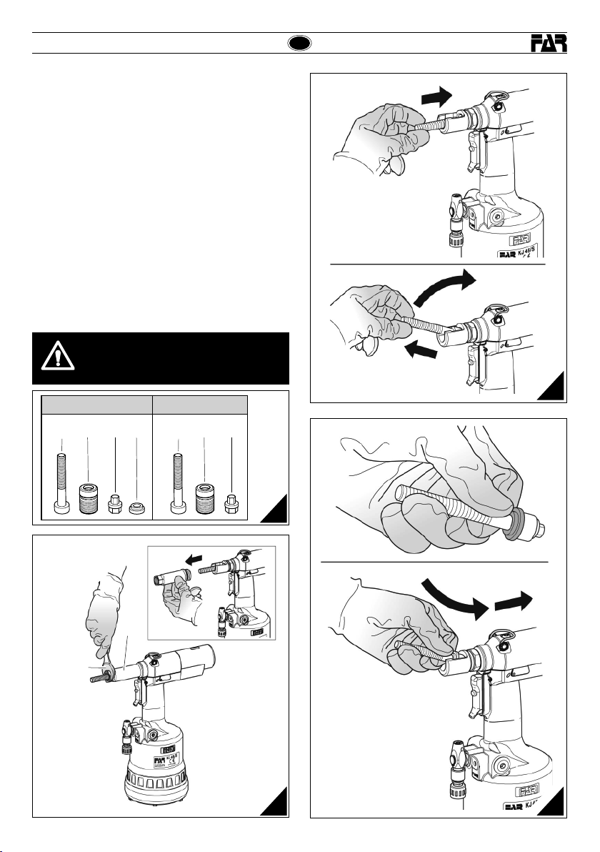
KJ 45/S
KJ 45/S
CAMBIO DEL FORMATO (fig. f8-f9 f10-f11)
La remachadora esta abasteacida con 6 parejas de tirantes
fileteados (A), cabezas (B), arrastradores (R) y, solo para
la serie de tirantes desde M4 hasta M6, de distanciadores
(S) (f8).
Para efectuar el cambio del formato proceder como sigue:
• destornillar el manguito porta cabeza (O) con una llave
comercial de mm 22 (f9).
• remover el tirante fileteado, empujarlo y entretanto
levantarlo (f10).
• despues la preparación del tirante fileteado (A) de la
medida querida, colocar y sostener los componentes
como en f11 y realizar el ensamblaje, asegurandose que
l as p ie z a s s e an en s es i ón d e b a la n ce d e m a ne r a c o rr e ct a ,
roteando el tirante de mano (f11).
ATENCION!
• El lado del componente (R) a insertar en la cabeza del
tirante esta imantado para evitar la caída accidental
durante las operaciónes del cambio del formato.
• Enroscar el manguito porta cabeza (O) por una llave
comercial de 22 mm y atornillar correctamente.
¡ATENCIÓN!
Las operaciones susodichas tienen que ser
efectuadas con la máquina parada.
M8 - M12M4 ÷ M6
ARB ARBS
E
f10
f8
O
22 mm
f9
Revisione - 08 Date 07-2016
f11
41
Page 42

E
KJ 45/S
KJ 45/S
REGULACIÓN DEL GRUPO TIRANTE CABEZA
(fig. f14-f15-f16)
Al variar la longitud de la tuerca a apretar hace falta regular
la posición de la c abeza (B) respecto al tirante fileteado (A).
Desconectar la remachadora de la alimentación del aire
comprimido.
A t o r n i l l a r u n a t u e r c a r e m a c h a b l e d e l a l o n g i t u d q u e r i d a s o b r e
el tirante fileteado manualmente hasta que la cabeza de la
tuerca toque la cabeza (B) de la remachadora. La cabeza es
ajust ada cor recta mente si e l tirant e filete ado sale d e la tuerc a
atornillado sobre sí mismo aproximadamente de 2 mm. En
caso c ontr ario des bloque ar la viro la (C) con una l lave es tánda r
de mm 22 pues atornillar o destornillar la cabeza (B) hasta
encontrar la justa posición, al final bloquear la virola (C).
¡ATENCIÓN!
Las operaciones susodichas tienen que ser
efectuadas con la máquina parada.
A
C
B
f15
C
22 mm
f16
B
f14
42 Date 07-2016 Revisione - 08
Page 43

KJ 45/S
KJ 45/S
LLENADO DE ACEITE DEL CIRCUITO OLEODINÁMICO
(fig. f17-f18)
Es necesario llenar el circuito oleodinámico de aceite luego de
un prolongado período de trabajo o al notar una disminución
de carrera de la remachadora. Proceder como sigue: con la
remachadora parada y en posición vertical, rodar el pomo
(M) hacia el signo “+” hasta el fin de carrera, quitar el tapón
(I) por m edio de la ll ave Allen de mm 4 (equipad a). Al efec tuar
est a operació n hay que tener c uidado que no o curran sa lidas
de aceite. Atornillar en la sede del tapón (I) el contenedor
aceite (T) (equipado) antes llenado de aceite hidráulico de
HLP 32 cSt .
Manteniendo la remachadora vertical, conectar la
alimentación del aire y apretar el pulsador (D) de manera
que la remachadora cumpla una serie de ciclos y acabe la
e m i s i ó n d e b u r b u j a s d e a i r e e n e l c o n t e n e d o r ( T), est o signi fica
que se ha acabado el llenado del aceite. Ahora desactivar la
alime ntación d el aire y, con la re machador a siempre ve rtica l,
destornillar el contenedor aceite ( T) y cer rarlo. C errar el t apón
(I) controlando la integridad de la arandela hermética y repetir
todos los ajustes para posicionar la tuerca remachable como
indicado en la pág. 38-39.
ATENCIÓN: Es muy importante seguir las instrucciones
susodichas y efectuar las operaciones de llenado aceite
con guantes.
Si se efectúa el vaciado completo del circuito hidráulico,
hay que coger todo el aceite en un contenedor apropiado
y contactar con una firma autorizada para la eliminación
de desechos.
¡ATENCIÓN!
¡Antes de desconectar el tubo del aire comprimido
de la remachadora, ¡asegurarse que éste no esté
bajo presión!
IMPORTANTE: Asegurarse que el tapón de llenado
aceite (I) sea enroscado con un par de acople
correspondiente a: Mín. 5 Nm ÷ Máx. 8 Nm.
Nosotros aconsejamos el uso del aceite HLP 32
cSt o similares
E
MANUTENCIÓN
Manutención diaria
- Controlar que el tirante fileteado no se encuentre estropeado.
- Controlar el sistema de alimentación del aire comprimido.
- Controlar que la carrera del utensilio sea apropiada
para introducir la tuerca remachable elegida (véase las
instrucciones relativas al ajuste de la carrera, indicadas en
la página 38).
- Controlar que no ocurran pérdidas de aire o de aceite. En
este caso sustituir posibles uniones o juntas estropeadas.
- Controlar que la presión máxima de alimentación sea 7 b ares .
Manutención semanal
- Controlar el nivel de aceite probando la carrera de
la remachadora. Si necesario llenar para prevenir
malfuncionamientos de la remachadora como indicado (fig.
f18).
Revisión de la remachadora
Se aconseja revisar completamente la remachadora después
de 600.000 ciclos o cada año.
En este caso dirigirse sólo a centros autorizados por la
FAR S.r.l.
ELIMINACIÓN DE LA REMACHADORA
f17
Revisione - 08 Date 07-2016
f18
Para eliminar la remachadora se guir con atenc ión
cuanto establecido por las leyes nacionales.
Despues de haber desconectado la remachadora
respecto del sistema neumatico, proceder
con el desmontaje de todos los componentes
dividendoles segun sus categorias: acero,
aluminio, material plastico, ecc.
La eliminación de los componentes deberá
efectuarse según lo dispuesto por las normas
vigentes.
43
Page 44

KJ 45/S
INSTRUKCJA OBSŁUGII
SPIS TREŚCI
GWARANCJA ................................................................................. 44
BEZPIECZNA PRACA Z NARZĘDZIEM .................................................... 44
IDENTYFIKACJA NARZĘDZIA .............................................................. 45
UWAGI OGÓLNE I ZAKRES ZASTOSOWANIA ........................................... 45
GŁÓWNE CZĘŚCI SKŁADOWE ............................................................. 45
DANE TECHNICZNE .......................................................................... 45
ZASILANIE POWIETRZEM .................................................................. 46
WSTĘPNE CZYNNOŚCI PRZED URUCHOMIENIEM ..................................... 46
MONTAŻ NITONAKRĘTKI...................................................................47
AWARYJNE URUCHOMIENIE NITOWNICY ............................................... 48
WYMIANA TRZPIENIA ...................................................................... 49
REGULACJA ZESPOŁU TRZPIEŃ GŁOWICA .............................................. 50
WYMIANA OLEJU ........................................................................... 51
KONSERWACJA .............................................................................. 51
UTYLIZACJA ZUŻYTEGO NARZĘDZIA .................................................... 51
GWARANCJA
Nitownice FAR są objęte 12-miesięczną gwarancją. Okres gwarancyjny
rozpoczyna się w chwili poświadczonego odbioru narzędzia przez klienta.
Użytkownikowi / kupującemu przysługuje gwarancja, jeśli narzędzie zostało
zakupione u autoryzowanego sprzedawcy i tylko w przypadu jego użytkowania
zgodnie z przeznaczeniem. Gwarancja nie obowiązuje, jeśli narzędzie nie jest
używanie lub jeśli nie jest poddawane pracom konserwacyjnym opisanym w
instrukcji obsługi i konserwacji. W przypadku wad lub usterek, rma FAR S.r.l.
zobowiązuje się wyłącznie do naprawy i/lub wymiany, według własnego uznania,
komponentów uznanych za wadliwe.
BEZPIECZNA PRACA Z NARZĘDZIEM
UWAGA!!!
Nie przestrzeganie podanych zaleceń bezpiecznej pracy,
może skutkować wypadkiem.
PL
• W razie kontaktu skóry z olejem należy umyć ręce mydłem alkalicznym.
• Narzędzie może być przenoszone ręcznie, po skończonej pracy zaleca się
jego przechowywanie w oryginalnym opakowaniu.
• W celu przedłużenia żywotności narzędzia zaleca się jego kwartalną
konserwację i przegląd.
• Prace naprawcze oraz czyszczenie maszyny należy przeprowadzać przy
urządzeniu odłączonym od zasilania w sprężone powietrze.
• Tam gdzie to możliwe zaleca się podwieszenie narzędzia na balanserze.
• W przypadku codziennej ekspozycji personelu w otoczeniu, w którym
poziom ciśnienia akustycznego emisji skorygowanego charakterystyką
A przekracza wartość bezpieczeństwa 70 dB (A), należy korzystać
z indywidualnych środków ochrony słuchu (nauszniki lub zatyczki
przeciwhałasowe, redukcja dziennego czasu ekspozycji, itd.)
• Miejsce pracy należy utrzymywać w czystości i porządku co zmniejsza
ryzyko wypadku.
• Narzędzia mogą używać tylko osoby do tego uprawnione.
• Upewnić się że przewody zasilające powietrza są odpowiednia dla
narzędzia.
• Narzędzie należy utrzymywać w czystości, nie wolno zdejmować osłony
tłumika.
• Nie szarpać narzędzia za przewód zasilania powietrzem, przewód z
powietrzem powinien być oddalony od źródeł ciepła.
• Po skończonej naprawie, upewnić się iż wewnątrz narzędzia nie zostały
klucze serwisowe.
• Przed odłączeniem rury sprężonego powietrza od nitownicy, należy
upewnić się, że nie jest ona pod ciśnieniem.
• Stosować się skrupulatnie do powyższych zaleceń.
UWAGA!
W razie silnego uderzenia nitownicy, należy natychmiast upewnić się
czy działa prawidłowo.
KJ 45/S
• Przed rozpoczęciem pracy należy zapoznań się z niniejszą instrukcją.
• W przypadku konieczności serwisowania narzędzia, należy skontaktować
się z autoryzowanym przedstawicielem rmy FAR ; używać tylko
oryginalnych części zamiennych, rma FA R nie ponosi żadnej
odpowiedzialności za wypadki powstałe na skutek niewłaściwego użycia
narzędzia (Dyrektywa UE 85/374).
Lista punktów serwisowych jest dostępna na naszej stronie
internetowej http://www.far.bo.it ( Organizacja )
• Narzędzie może być stosowane tylko przez odpowiednio przeszkolone
osoby.
• W czasie pracy z urządzeniem, należy korzystać z okularów lub osłon
ochronnych oraz rękawic.
• W trakcie czynności serwisowych należy stosować klucze z wyposażenia
narzędzia, lub inne akcesoria o których mowa w rozdziale “Konserwacja”
w niniejszej instrukcji.
• Przy wymianie oleju należy stosować olej o parametrach podanych w
instrukcji.
44 Date 07-2016 Revisione - 08
Page 45

KJ 45/S
KJ 45/S
PL
IDENTYFIKACJA NARZĘDZIA
Na nitownicy KJ 45/S jest identy kowana poprzez oznaczenie obejmujace nazwe
i adres producenta, okreslenie maszyny, oznakowanie CE.
Korzystając z pomocy technicznej należy zawsze podać dane znajdujące się
na nitownicy.
Firma i adres Określenie maszynya
GŁÓWNE CZĘŚCI SKŁADOWE
A) ........................................................................Śruba imbusowa
B) ...................................................................................Głowica
C) ..........................................................Pierścień kontrujący głowicy
D) .................................................... Przycisk uruchamiania nitownicy
E) .................................................... Zasilanie sprężonym powietrzem
F) ................................................................. Zawór nadciśnieniowy
G) ..................................................................... Nakładka ochronna
H) .................................................................. Silnik pneumatyczny
I)....................................................................Korek zbiornika oleju
L) .................................................................... Zaczep do balansera
M) ........................................................ Pokrętło regulacji siły zacisku
N) .............................................................Wskaźnik skoku trzpienia
O) ........................................................................... Tuleja głowicy
P) .................................................................... Prz ycisk wykręcania
Q) ................................................................ Zawór wlotu powietrza
fabrycznie montuje się na nitownicy trzpień m10
*
Numer wiele
UWAGI OGÓLNE I ZAKRES ZASTOSOWANIA
Nitownica KJ 45/S jest przeznaczona do nitonakrętek o średnicy M4-M12.
System oleo-pneumatyczny zastosowany w tym modelu pozwala na uzyskanie
większej mocy zacisku nitonakrętki w porównaniu do starszych modeli nitownic.
Gwarantuje to znaczne zmniejszenie problemów ze zużyciem uszczelniaczy, a tym
samym uzyskujemy dłuższą żywotność samego narzędzia. Rozwiązania techniczne
zastosowane w nitownicy KJ 45/S znacznie zmniejszyły ciężar narzędzia i
polepszyły jego ergonomię. Ponadto udoskonalony system uszczelniaczy eliminuje
możliwość spadku mocy zacisku.
Revisione - 08 Date 07-2016
DANE TECHNICZNE
• Ciśnienie robocze ....................................................... 6 - 7 BAR
• Minimalna średnica wewn. przewodu
zasilania ....................................................................... 8 mm
• Zużycie maks. powietrza na cykl ..........................................9 Nl**
• Siła maksymalna ..........................................6,5 BAR - 27440 N
• Waga (z trzpieniem M10) ..............................................2,860 Kg
• Temperatura otoczenia ..................................................-5°/+50°
• Częstotliwość przyspieszenia (Ac) ...................................< 2,5 m/s
** nl = litry przy 20°C, ciśnienie atmosferyczne
• Ciśnienie akustyczne emisji skorygowane charakterystyką A ........ 74 dBA
• Chwilowe ciśnienie akustyczne skorygowane charakterystyką C <130 dBC
• Moc akustyczna skorygowana charakterystyką A ......................86 dBA
2
45
Page 46

PL
KJ 45/S
KJ 45/S
ZASILANIE POWIETRZEM (rys f1)
Instalacja powinna posiadać urządzenia oczyszczające powietrze i umożliwiać
odpływ kondensatu i powinna zapewniać na wejściu stałe ciśnienie 6 bar.
Regulator ciśnienia powinien być ustawiony na 6,5 bar.
Nitownicę podłączamy jak poniżej (f1):
1) Zawór odcinający dopływu powietrza (uży wane przy okazji konserwacji ltru
lub jednostki naolejającej powietrze).
2) Główny punkt poboru powietrza.
3) Punkt odpowietrzania głównej linii zasilającej.
4) Regulator ciśnienia i ltr (odpowietrzanie codzienne).
5) Naolejacz powietrza.
UWAGA! Nitownica jest wyposażona w zawór nadciśnieniowy
(F), ograniczający nagły skok ciśnienia, przekraczający 7 bar.
UWAGA! W przypadku interwencji zaworu ograniczającego
ciśnienie (F) i, w konsekwencji, ujścia powietrza, należy
sprawdzić czy ciśnienia zasilające maszynę odpowiada
ciśnieniu wskazanemu w danych technicznych niniejszej
instrukcji (str. 45).
f1
3 m Max
1
2
WSTĘPNE CZYNNOŚCI PRZED URUCHOMIENIEM (rys f2-f3)
Sprawdzamy czy trzpień gwintowany (A) i głowica (B) które są na nitownicy
mają żądaną średnicę. Jeżeli tak nie jest, wymieniamy je na żądaną średnicę.
Zespół trzpień gwintowany (A) + głowica (B) zamontowany na nitownicy w
opakowaniu, posiada gwint M10.
Po każdej wymianie trzpienia na inną średnicę upewniamy się że regulacja siły
zacisku jest prawidłowa.
Obracając pokrętło M w kierunku znaku (+) zwiększamy siłę zacisku (zmniejsza się
odległość “h” (s. 47), zob. na kolejnej stronie), obracając pokrętło (M) w kierunku
znaku (-) zmniejszamy siłę zacisku nitonakrętki. Aby upewnić się czy regulacja
została ustawiona prawidłowo spoglądamy na wskaźnik (N) i porównujemy
położenie kursora ze wskazaniami z tabeli poniżej.
Uwaga: przed ostatecznym zamocowaniem nitonakrętki, zaleca się sprawdzenie
czy regulacja siły zacisku jest odpowiednia (zob. wskazówki podane na s. 50).
UWAGA! Nieprawidłowa regulacja skoku trzpienia może
powodować złe mocowanie nitonakrętki lub uszkodzenie
samego trzpienia!
UWAGA! W czasie przeprowadzania wyżej wymienionych
czynności maszyna musi być odłączona od zasilania. Aby
wyświetlić zmieniony skok (N), należy podłączyć maszynę
do zasilania.
3
4
5
ZESPÓŁ FRL
(zespół przygotowania powietrza)
F
Q
• Celem zasilenia urządzenia, należy przesunąć suwak zaworu wlotu powietrza (Q) do
góry.
• Celem wypuszczenia powietrza z urządzenia i zatrzymania zasilania, należy przesunąć
suwak zaworu wlotu powietrza (Q) w dół; dopiero w tym momencie można
przeprowadzić czynności związane z regulacją skoku.
46 Date 07-2016 Revisione - 08
f2
Page 47

KJ 45/S
KJ 45/S
PL
f3
1
M
8
9
10
11
12
13
M12
1 ÷ 4
Max skok drążka Obroty (M)
~ 8 mm 15
14
15
Skok drążka Obroty (M)
~ 0.4 mm 1
MONTAŻ NITONAKRĘTKI (rys f4-f5-f6)
Upewniamy się że na nitownicy jest zamontowany trzpień (A) oraz głowica (B) o
żądanej średnicy, oraz czy regulacja siły zacisku jest prawidłowa. Skok trzpienia
regulujemy wg wskazówek podanych (rys f2-f3).
Na gwintowany trzpień (A) nakładamy nitonakrętkę, pod wpływem lekkiego
nacisku trzpień wkręci się automatycznie (rys f4). Upewniamy się że kołnierz
nitonakrętki styka się z krawędzią głowicy (B) i że trzpień wystaje z nitonakrętki
na ok. 2 mm (A).
W tym momencie mozemy przystapic do montazu nitonakretki trzymajac wcisniety
przycisk (D) (rys. f5) az do calkowitego zacisniecia nitonakretki; w celu wykrecenia
trzpienia, nalezy nacisnac przycisk (P) (rys. f7).
Aby nitonakrętki prawidłowo mocowały się w otworach muszą być czyste.
Uwaga: jeżeli jest to konieczne dokonujemy korekty regulacji skoku trzpienia
(siły zacisku) pokrętłem (M) (rys f2-f3-f6).
Nitonakrętka słabo zaciśnięta = nitonakrętka może się obracać w otworze
co ma negatywny wpływ na jej funkcję i parametry jakościowe
Nitonakrętka zaciśnięta za mocno = istnieje ryzyko uszkodzenia
gwintowanego trzpienia (A) lub nitonakrętki.
M
1
2
1
÷
7
/
M
6
0
.
5
÷
1
÷
0
6
M
8
0
.
8
÷
6
M
5
0
.
5
÷
7
6
6
5
M
4
0
.
3
÷
5
4
3
4
2
1
0
Min skok drążka Obroty (M)
~ 2 mm 0
D
f5
f4
BA
Revisione - 08 Date 07-2016
M
f6
47
Page 48

PL
KJ 45/S
KJ 45/S
AWARYJNE URUCHAMIANIE NITOWNICY (rys f7)
W przypadku, gdy zachodzi potrzeba wymuszonego wykręcania gwintowanego
trzpienia z nitonakrętki, należy wcisnąć przycisk (P).
UWAGA! Powyższą czynność wykonujemy mocno trzymając
nitownicę, w przeciwnym razie jej gwałtowne poruszenie może
doprowadzić do uszkodzenia lub zagrażać użytkownikowi .
f7
48 Date 07-2016 Revisione - 08
Page 49
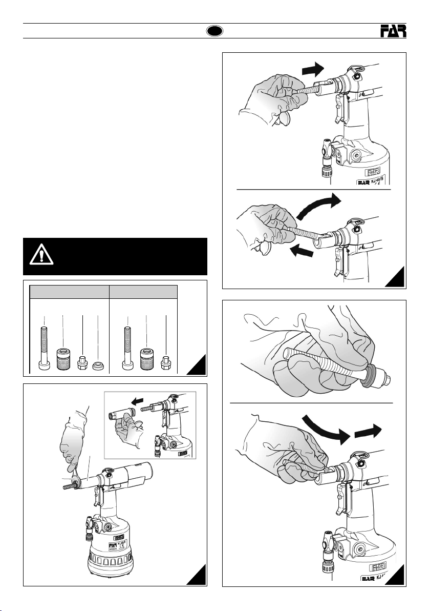
KJ 45/S
KJ 45/S
ZMIANA FORMATU (rys. f8-f9 f10-f11)
Nitownica zostaje dostarczona z 6 parami trzpieni gwintowanych (A), głowic
(B), zabieraków (R) i, tylko dla serii trzpieni gwintowanych od M4 do M6,
przekładek (S) (f8).
Celem przeprowadzenia zmiany formatu, należy:
• Odk ręcić rurkę noś ną głowicy (O) za po mocą klucz a 22 mm (f9).
• Wy jąć trzpie ń gwintowany, pop ychając go i równ ocześnie u nosząc go do
góry (f10).
• Przygotowawszy gwintowany trzpień (A) o żądanym ro zmiarze, należy
rozmieścić poszczególne elementy tak, jak to pokazano na rys. f11 i
przeprowadzić montaż, upewniając się, że komponenty zosta ły poprawnie
wsunięt e na swoje miejsce, p oprzez ręcz ne obracania t rzpienia (f11).
UWAGA!
• W elemencie (R) strona, którą należy w prowadzić do głow icy trzpienia
jest nama gneso wana, co za bezpi ecz a przed e wentual nym wy padnię ciem
w czasi e zmiany formatu .
• Przy kręci ć rurkę no śną gło wicy (O) za pomocą klucza 22 mm i prawidłowo
docisnąć.
UWAGA!
Opisane wyżej czynności wykonujemy przy nitownicy
odłączonej od zasilania!
M8 - M12M4 ÷ M6
ARB ARBS
PL
f10
f8
O
22 mm
f9
Revisione - 08 Date 07-2016
f11
49
Page 50

PL
KJ 45/S
KJ 45/S
REGULACJA ZESTAWU TRZPIEŃ- GŁOWICA
(rys f14-f15-f16)
W zależności od długości nitonakrętki jaką stosujemy należy wyregulować
ustawienie głowicy (B) względem trzpienia (A).
Odłączyć zasilanie w sprężone powietrze od nitownicy.
Ręcznie nakręcamy nitonakrętkę na gwintowany trzpień, tak aby kołnierz
nitonakrętki dotykał krawędzi głowicy (B). Pozycja głowicy jest prawidłowa
jeżeli trzpień wychodzi z nitonakrętki na ok. 2 mm.
W przeciwnym razie, poluzować pierścień C kluczem 22 mm, następnie obrócić
głowicę tak aby trzpień wychodził z nitonakrętki na 2 mm. Następnie blokujemy
głowicę (B) pierścieniem blokującym (C).
Uwaga! Powyższe czynności wykonujemy kiedy nitownica
jest odłączona od zasilania.
A
C
B
f15
C
22 mm
f16
B
f14
50 Date 07-2016 Revisione - 08
Page 51

KJ 45/S
KJ 45/S
WYMIANA OLEJU (rys f17-f18)
Po dłuższym okresie pracy należy wymienić olej, szczególnie gdy zauważamy
spadek mocy nitownicy.
W tym celu należy:
• odłączyć nitownicę od zasilania;
• pokrętło (M) obracamy do końca w kier. Znaku “+”;
• ustawiamy nitownicę w pionie i odkręcamy korek (I) imbusem 4 mm (jest
na wyposażeniu nitownicy);
• w otwór korka wkręcamy pompkę oleju (T) (na wyposażeniu nitownicy)
wypełnioną olejem o HLP 32 cSt ;
• utrzymując nitownicę w pionie, podłączamy zasilanie powietrzem i naciskamy
kilka razy przycisk (D), dopóki w pompce przestana pojawiać się bańki
powietrza;
• odłączamy zasilanie powietrzem;
• wykręcamy pompkę oleju (T);
• wkręcamy ponownie korek (I) (s. 46-47).
OSTROŻNIE: Przestrzeganie podanych wyżej instrukcji jest bardzo ważne, jak
również przeprowadzanie operacji dolania oleju z założonymi rękawicami.
W przypadku całkowitego opróżniania obiegu hydraulicznego, należy zlać cały olej
do odpowiedniego pojemnika, a następnie skorzystać z usług rmy upoważnionej
do usuwania odpadów.
UWAGA! Przed odłączeniem przewodu powietrza od
nitownicy, upewnić się że nie jest on pod ciśnieniem!
UWAGA! Upewnić się że korek wlewu oleju (I) został
dokręcony z siłą równą Min. 5 NM- Maks. 8 Nm.
Zaleca się użycie oleju HLP 32 cSt lub podobnych.
PL
f18
KONSERWACJA
Konserwacja codzienna:
• sprawdzamy czy gwintowany trzpień nie jest uszkodzony;
• sprawdzamy instalację zasilania powietrzem;
• sprawdzamy czy siła zacisku jest odpowiednio ustawiona do danej nitonakrętki
(s. 46);
• upewnić się że nie ma wycieków oleju lub nieszczelnych przewodów powietrza;
• upewnić się ze ciśnienie zasilające nie przekracza 7 bar.
Konserwacja tygodniowa:
• sprawdzamy poziom oleju (rys f18).
Przegląd serwisowy
Zalecamy gruntowny przegląd narzędzia po 600.000 cykli lub corocznie.
W takim przypadku, przeglądu może dokonać tylko autoryzowany serwis FAR.
UTYLIZACJA ZUŻ YTEGO NARZĘDZIA
f17
Revisione - 08 Date 07-2016
W przypadku zużytego narzędzia, jego utylizacje przeprowadzamy
zgodnie z przepisami danego kraju.
Po odłączeniu urządzenia od instalacji pneumatycznej, należy
przystąpić do demontażu poszczególnych komponentów,
segregując je w zależności od ich typologii: stal, aluminium,
materiał plastikowy, itd.
51
Page 52

RUS
KJ 45/S
KJ 45/S
ИНСТРУКЦИИ ПОA ИСПОЛЬЗОВАНИЮI
СОДЕРЖАНИЕ
ГАРАНТИЙНЫЕ ОБЯЗАТЕЛЬСТВА ...................................................................52
РЕКОМЕНДАЦИИ И МЕРЫ БЕЗОПАСНОСТИ ................................................... 52
ИДЕНТИФИКАЦИОННЫЕ ДАННЫЕ ЗАКЛЁПЫВАЮЩЕГО АППАРАТА .............. 53
ОБЩИЕ ЗАМЕЧАНИЯ И ОБЛАСТЬ ПРИМЕНЕНИЯ ........................................... 53
ОСНОВНЫЕ УЗЛЫ .......................................................................................... 53
ТЕХНИЧЕСКИЕ ДАННЫЕ ................................................................................. 53
ПОДАЧА ВОЗДУХА ......................................................................................... 54
ПОДГОТОВИТЕЛЬНЫЕ ОПЕРАЦИИ.................................................................. 54
УСТАНОВКА ВСТАВКИ. ................................................................................... 55
АНОМАЛИИ В РАБОТЕ ................................................................................... 56
СМЕНА ФОРМАТА ........................................................................................... 57
РЕГУЛИРОВКА БЛОКА ТЯГОВОЙ ШТАНГИ ГОЛОВКИ ...................................... 58
ДОЛИВКА МАСЛА В ГИДРОДИНАМИЧЕСКИЙ КОНТУР С МАСЛЯНОЙ СРЕДОЙ ........... 59
ТЕХНИЧЕСКОЕ ОБСЛУЖИВАНИЕ .................................................................... 59
ПЕРЕРАБОТКА ЗАКЛЁПЫВАЮЩЕГО АППАРАТА. ............................................ 59
ГАРАНТИЙНЫЕ ОБЯЗАТЕЛЬСТВА
Заклёпочные инструменты производства фирмы Far имеют гарантию
на срок 12 месяцев. Период гарантийного обслуживания начинается
с момента документально подтвержднного факта получения прибора
покупателем. Гарантийное обязательство распоространяется на прибор,
принадлежащий пользователю/покупателю при условии, что прибор был
приобретен у официального дистрибьютора и только для предусмотренного в
руководстве по эксплуатации и техническому обслуживанию использования.
Гарантийное обязательство считается расторгнутым, если прибор не
используется и не подвергается техническому обслуживанию в строгом
соответствии с инструкциями в руководстве по эксплуатации и техническому
обслуживанию. При наличии брака или повреждений Компания Far S.r.l.
берет на себя только обязательство починить и/или заменить те детали,
которые, по собственному усмотрению, будет считать бракованными.
РЕКОМЕНДАЦИИ И МЕРЫ БЕЗОПАСНОСТИ
ВНИМАНИЕ!!!
Невыполнение или небрежность в исполнении
последующих мер предосторожности может привести
к неприятным последствиям для вашей и чужой
невредимости, и для хорошего функционирования
инструмента.
• Перед началом эксплатации аппарата необходимо внимательно
ознакомиться с руководством по эксплуатации.
• Для проведения технического обслуживания и/или ремонта
обращаться в официальные центры поддержки, имеющие
авторизацию компании FAR s.r.l. и пользоваться только
оригинальными запасными частями. Компания FAR
s.r.l. снимает с себя ответственность за ущерб, причинённый
бракованными деталями, вследствие несоблюдения приведенных
выше правил (Директива CEE 85/374).
Список сервисных центров приведен на нашем
веб-сайте http://www.far.bo.it ( ОРГАНИЗАЦИЯ )
• Работать с оборудованием рекомендуется квалифицированному
персоналу.
• При работе с аппаратом пользоваться защитными очками или
масками для лица и перчатками.
• При выполнении техобслуживания и/или регулировки оборудования
пользоваться поставляемыми принадлежностями и/или стандартным
инструментом, указанным в главе Техническое обслуживание.
• Для загрузки масла пользоваться только жидкостями, имеющими
характеристики, указанные в настоящем пособии.
• При случайной утечке масла и в случае его попадания на кожу,
необходимо тщательно промыть пораженный участок кожи водой с
щелочным мылом.
• Данное оборудование можно транспортировать вручную и после
работы мы рекомендуем поместить его обратно в упаковку.
• Для правильного функционирования заклёпывающего аппарата
рекомендуется проводить технический осмотр каждые шесть
месяцев.
• Технический осмотр и очистка должны осуществляться на
отсоединённом оборудовании.
• Рекомендуется, при возможности, пользоваться балансиром
безопасности.
• В случае ежедневной работы операторов в помещении, в котором
эквивалентный уровень испускаемого звукового давления A
превышает предельное значение безопасности 70 дБ (A), необходимо
пользоваться индивидуальными средствами защиты органов слуха
(наушники или бируши; снизить время нахождения в шумном
помещениии т.п.).
• Сделить за порядком на рабочем месте, беспорядок на рабочем месте
может стать причиной травмирования персонала.
• Недопускать посторонних к работе с оборудованием.
• Убедиться в том, что шланги подачи сжатого воздуха выбраны
правильно, в соответствии с предусмотренным использованием.
• Не тянуть подсоединённый аппарат за шланг подачи сжатого воздуха.
Шланг должен располагаться на расстоянии от источников тепла и
режущих предметов.
• Держать оборудование в хорошем состоянии и в чистоте; никогда не
удалять с аппарата защитные устройства и глушитель.
• После выполнения техобслуживания и/или регулировки оборудования
убедиться в том, что рабочие или регулировочные ключи удалены.
• Перед тем, как отсоединить шланг подачи сжатого воздуха от аппарата
убедиться в том, что он не находится под давлением.
• Тщательно следовать данным инструкциям.
ВНИМАНИЕ! После падения или сильного удара оборудования
необходимо проверить его общую целостность.
52 Date 07-2016 Revisione - 08
Page 53

KJ 45/S
KJ 45/S
RUS
ИДЕНТИФИКАЦИОННЫЕ ДАННЫЕ ЗАКЛЁПЫВАЮЩЕГО АППАРАТА
Заклёпочный аппарат KJ 45/S идентифицируется при помощи маркировки,
в которой указывается наименование предприятия и адрес изготовителя,
предназначение аппарата, маркировка CE .
При обращении за технической поддержкой всегда указывайте
идентификационные данные аппарата.
наименование предприятия и
адрес изготовителя
предназначение аппарата
ОСНОВНЫЕ УЗЛЫ
A) ....................................................................Распорка с резьбой
B) .................................................................................. Головка
C) ......................................................Блокирующее кольцо головки
D) ................................................................... Кнопка управления
E) .................................................. Присоединение сжатого воздуха
F) ............................................................. Ограничитель давления
G) ...................................................................... Защитное днище
H) ........................................................Пневматический двигатель
I)...............................................................Пробка масляного бака
L) .......................................................... Присоединение балансира
M) ........................................................ Рукоятка регулировки хода
N) ........................................................................Указатель хода
O) .......................................................... Втулка крепления головки
P) ...........................................................Кнопка для отвинчивания
Q) .............................................................. Клапан подачи воздуха
с распоркой для М10
*
номер партии
ТЕХНИЧЕСКИЕ ДАННЫЕ
ОБЩИЕ ЗАМЕЧАНИЯ И ОБЛАСТЬ ПРИМЕНЕНИЯ
Аппарат предназначается для эксплуатации исключительно с применением
вставок с резьбой от М4 до М12.
Масляно – пневматическая система, используемая заклёпочным
аппаратом KJ 45/S, даёт большую мощность по сравнению с традиционной
пневматической системой, которую используют другие модели
заклёпочных аппаратов. Это означает значительное снижение трудностей,
связанных с износом деталей и, следовательно, возрастает надёжность
и продолжительность срока эксплуатации. Технические решения,
использованные при разработке данной модели, позволили снизить
размеры и вес и сделали заклёпывающий аппарат KJ 45/S очень удобным
в обращении инструментом. Вероятность утечек гидродинамической
системы (с масляной средой) сведена к нулю, благодаря использованию
герметических уплотнений, которые полностью решают данную проблему.
Revisione - 08 Date 07-2016
• Рабочее давление ............................................................................6 - 7 ар
• Минимальный внутренний диаметр шланга
подачи сжатого воздуха .................................................................... 8 мм
• Максимальное потребление свободного воздуха за цикл .............9 нл**
• Максимальное усилие ...................................................6,5 ар - 27440 кН
• Вес (с оборудованием для М10) ....................................................2,860 кг
• Температура эксплуатации ...........................................................-5°/+50°
• Суммарное значение частотно – взвешенного среднеквадратичного
ускорения (Ac), которому
подвергаются верхние конечности ..........................................< 2,5 m/s
** нл = литры при температуре 20°C и атмосферном давлении
• Эквивалентный уровень испускаемого звукового давления (A) . 74 dBA
• Эквивалентный уровень мгновенного значение звукового
давления (C) ...............................................................................<130 dBC
• Эквивалентный уровень звукового давления (A) ..........................86 dBA
2
53
Page 54

RUS
KJ 45/S
KJ 45/S
ПОДАЧА ВОЗДУХА (рисунке f1)
Система сжатого воздуха должна включать устройства для очистки воздуха,
для удаления конденсата и должна гарантировать постоянное значение
давления на подаче в аппарат равное мин. 6 бар. Регулятор должен быть
установлен на давление 6,5 бар.
Подсоединить аппарат к подаче сжатого воздуха, следуя инструкциям на
схеме на рисунке (f1):
1) Запорный кран (используется при проведении техничекого обслуживания
фильтра – регулятора или смазочного блока).
2) Точка забора от основной магистрали.
3) Точка отвода к основной магистрали.
4) Фильтр и регулятор давления (очищать ежедневно).
5) Смазчик.
ВНИМАНИЕ! Заклёпывающий Аппарат снабжен
ограничительный клапаном (F), который срабатывает
в случае, когда давление сжатого воздуха превышает
значение 7 бар.
ВНИМАНИЕ! В случае срабатывания ограничительныого
клапана (F) и последующего выброса воздуха, необходимо
проверить значение давления подачи воздуха в аппарат,
которое должно соответствовать значению, указанному в
разделе технических данных настоящего пособия (стр. 53).
f1
3 m Max
1
2
ПОДГОТОВИТЕЛЬНЫЕ ОПЕРАЦИИ (рисунке f2-f3)
Убедиться в том, что набор – распорка с резьбой (А) и головка (В),
установленные на заклёпывающем аппарате, соответствуют размеру
вставки; в противном случае необходимо произвести смену формата (стр.
57). Блок резьбовая тяговая штанга (А) + головка (В) смонтированные на
заклёпывающем аппарате на предприятии – изготовителе соответствуют
резьбе М10.
Перед использованием заклёпывающего аппарата и после каждой смены
формата необходимо отрегулировать ход в соответствии с размерами, типом
вставки и толщиной зажимаемого материала. Перед тем, как осуществлять
эту операцию, необходимо повернуть рукоятку (М) по направлению стрелки
в сторону (+) для того, чтобы увеличить ход и в сторону (-) чтобы его
уменьшить. Помнить о том, что при увеличении хода – повороте ручки
(М) в сторону, указываемую условным знаком (+) расстояние “h” (стр.
55) уменьшается и, следовательно, увеличивается зажимное действие.
Для того, чтобы проверть правильно ли отрегулирован ход, необходимо
проверить указатель (N) и сравнить его значение с табличным (рис. f3).
Примечание: перед окончательной установкой вставки рекомендуется
проверить её зажим на требуемой толщине, проведя дополнительную
регулировку, как показано на странице 58 (указанные регулировки
приведены в качестве типичного примера; рекомендуется навести справки
о технических характеристиках используемых вставок).
ВНИМАНИЕ! Неправильная регулировка хода
заклёпывающего аппарата может стать причиной плохого
зажима вставок и вероятной причиной поломки распорки.
ВНИМАНИЕ! Указанные выше операции должны
производиться только с отсоединённым заклёпывающим
аппаратом. Для визуализации изменённого хода (N)
необходимо присоединить аппарат к электропитанию.
3
4
5
БЛОК FRL
F
Q
• Для питания аппарата необходимо переместить ползун клапана подачи
воздуха (Q) вверх.
• Для того, чтобы выпустить воздух из аппарата и заблокировать подачу
переместить ползун клапана подачи воздуха (Q) вниз и только затем
осуществлять регулировку хода.
54 Date 07-2016 Revisione - 08
f2
Page 55

KJ 45/S
KJ 45/S
RUS
f3
1
M
8
9
10
11
12
13
M12
1 ÷ 4
Максимальный ход распорки
~ 8 mm 15
14
15
Обороты (M)
Ход распорки Обороты (M)
~ 0.4 mm 1
УСТАНОВКА ВСТАВКИ (рисунке f4-f5-f6)
Убедиться в том, что набор – распорка с резьбой (А) и головка (В),
установленные на заклёпывающем аппарате, соответствуют размеру
вставки. Отрегулировать ход как описано на (рис. f2-f3).
Поместить вставку на распорку (А) и произвести на неё небольшое давление,
как показано на рисунке f4. Таким образом, вставка автоматически
направляется на распорку с резьбой. Убедиться в том, что головка вставки
соприкасается с головкой (В) и проверить выступает ли распорка из
вставки на 2 мм.
При проведении дополнительной регулировки распорки следовать порядку
действий, описанному на странице 58.
Теперь, можно установить вставку, нажав на кнопку (D) ( g.f5) до полной
установки; для освобождения распорки нажать на кнопку (P) ( g.f7).
Для правильной установки и корректного функционирования аппарата
необходимо, чтобы устанавливаемые вставки были бы очищены
соответствующим образом.
Примечание: при необходимости, в зависимости от требуемого зажима,
произвести дополнительную регулировку хода заклёпывающего аппарата,
посредством вращения рукоятки (М) (рис. f2-f3-f6).
Недостаточная деформация = вставка может вращаться внутри гнезда
и поставить под угрозу продолжительность эксплуатации и стойкость.
Избыточная деформация = вероятные повреждения вставки и распорки
(А) и вероятная поломка обоих компонентов.
f4
M
1
2
1
÷
7
/
M
6
0
.
5
÷
1
÷
0
6
M
8
0
.
8
÷
6
M
5
0
.
5
÷
7
6
6
5
M
4
0
.
3
÷
5
4
3
4
2
1
0
Минимальный ход распорки Обороты (M)
~ 2 mm 0
D
f5
M
BA
Revisione - 08 Date 07-2016
f6
55
Page 56

RUS
KJ 45/S
KJ 45/S
АНОМАЛИИ В РАБОТЕ (рисунке f7)
Во всех случаях, когда требуется принудительно отвинтить резьбовую
распорку от вставки, нажать на кнопку (P).
ВНИМАНИЕ! Производить данные действия крепко
держа заклёпывающий аппарат, чтобы предотвратить
резкие движения, которые могут нанести ущерб людям
или оборудованию.
f7
56 Date 07-2016 Revisione - 08
Page 57

KJ 45/S
KJ 45/S
СМЕНА ФОРМАТА (рис. f8-f9-f10-f11)
Заклёпывающий аппарат поставляется с 6-ю парами резьбовой тяговой
штанги (A), головки (B), носителей (R) и, только для серии с тяговой штангой
от M4 до M6 – прокладочным кольцом (S) (f8).
Для того, чтобы выполнить смену формата необходимо следовать
приведенному ниже порядку действий:
• О твинтить в тулку кре пления голо вки (O) при помощи с тандартн ого
ключа 22 мм (f9).
• Удалить ре зьбовую тяговую штангу, для этого необходимо нажать
на неё и одно временно прип однять (f10).
• Посл е того, ка к будет выб рана тя гова я штанг а (A) требуем ого разм ера,
необходимо разместить и поддерживать компоненты как показано
на рисунке f11 и выполнить сбор ку аппарата; убе диться в том, что
детали правильно установлены в гнёзда, для этого необходимо
вращат ь вручную тягову ю штангу (f11).
ВНИМАНИЕ!
• У компонента (R) сторона, которая вставляется в головку тяговой
штанги на магничена д ля того, чтобы из бежать сл учайного па дения
при смен е формата.
• Зак рутить вт улку крепл ения головки (O) при п омощи стан дартного
ключа 22 мм и правильно её з акрепить.
ВНИМАНИЕ!
Производить данные операции только с отсоединенным
заклёпывающим аппаратом.
RUS
ARB ARBS
22 mm
M8 - M12M4 ÷ M6
f10
f8
O
f9
Revisione - 08 Date 07-2016
f11
57
Page 58

RUS
KJ 45/S
KJ 45/S
РЕГУЛИРОВКА БЛОКА ТЯГОВОЙ ШТАНГИ ГОЛОВКИ (рисунке f14-f15-f16)
При изменении длины зажимаемой вставки необходимо отрегулировать
положение головки (В) по отношению к резьбовой распорке (А).
Перекрыть подачу сжатого воздуха к заклёпывающему аппарату.
Завинтить, вручную, вставку требуемой длины на резьбовую распорку
до тех пор, пока головка вставки не будет соприкасаться с головкой (В)
заклёпывающего аппарата. Головка отрегулирована правильно, если
распорка выступает примерно на 2 мм из накрученной на неё вставки.
В противном случае, необходимо разблокировать зажимное кольцо (С),
при помощи стандартного ключа 22 мм, а затем отвинтить или завинтить
головку (В), пока не будет достигнуто требуемое положение. В конце
заблокировать зажимное кольцо (С).
ВНИМАНИЕ!
Производить данные операции только с отсоединенным
заклёпывающим аппаратом.
A
C
B
f15
C
22 mm
f16
B
f14
58 Date 07-2016 Revisione - 08
Page 59

KJ 45/S
KJ 45/S
ДОЛИВКА МАСЛА В ГИДРОДИНАМИЧЕСКИЙ КОНТУР С МАСЛЯНОЙ
СРЕДОЙ (рисунке f17-f18)
Доливка масла в гидродинамический контур с масляной средой становится
необходимой после длительного периода эксплуатации или когда
наблюдается уменьшение хода заклёпывающего аппарата. Действовать
следующим образом: с отсоединённым заклёпывающим аппаратом
вращать рукоятку (М) в сторону, указанную условным знаком “+” до
конечного останова, поместить аппарат вертикально, удалить пробку (I)
при помощи шестигранного ключа 4 мм (входящего в комплектацию). При
проведении данных операций необходимо обратить особое внимание на то,
чтобы не разлить масло. На место пробки необходимо поместить ёмкость
для масла (T) (входящую в комплектацию), которую нужно предварительно
заполнить маслом для гидравлических систем HLP 32 cSt .
Держать заклёпывающий аппарат вертикально, включить подачу воздуха,
нажав на кнопку (D) и дать выполнить заклёпывающему аппарату ряд
циклов, пока подача пузырьков воздуха в ёмкость для масла полнос тью не
кончится (T). Это означает, что доливка масла в контур выполнена. Затем,
выключить подачу воздуха и, продолжая держать заклёпывающий аппарат
вертикально, отвинтить ёмкость для масла (T) и закрыть её. Поместить
на место пробку масляного бака, проверить целостность герметической
прокладки и повторить все регулировки для помещения вставки, описанные
на странице 54-55.
МЕРЫ ПРЕДОСТОРОЖНОСТИ: очень важно следовать приведенным
выше инструкциям и проделывать доливку масла в защитных перчатках.
При полном опорожнении гидравлического контура необходимо собрать
всё масла в специальную ёмкость и передать в специальный пункт по сбору
и переработке промышленных отходов.
ВНИМАНИЕ!
Перед тем, как отсоединять шланг подачи сжатого воздуха
от заклёпывающего аппарата убедиться в том, что он не
под давлением!
ВНИМАНИЕ!
Убедиться в том, что пробка масляного бака (I)
завинчивается с усилием затяжки от мин. 5 Нм до
макс. 8 Нм.
Рекомендуется использовать масло HLP 32 cSt или
подобное
RUS
f18
ТЕХНИЧЕСКОЕ ОБСЛУЖИВАНИЕ
Повседневное обслуживание
• Проверить целостность резьбовой тяговой штанге.
• Проверить систему подачи сжатого воздуха.
• Проверить подходит ли ход аппарата для установки выбранной вставки
(смотрите инструкции по регулировке хода на странице 54).
• Проверить имеются ли утечки воздуха или масла. При их наличии,
заменить повреждённые фитинги или прокладки.
• Проверить давление подачи сжатого воздуха, которое не должно
превышать макс. 7 бар.
Еженедельное обслуживание
• Проверить уровень масла, путём проверки хода заклёпывающего
аппарата. При необходимости добавить масла, чтобы избежать
повреждения заклёпывающего аппарата, следуя порядку действий,
описанному на странице (f18).
Технический осмотр
Рекомендуется производить полный технический осмотр заклёпывающего
аппарата после 600.000 рабочих циклов или раз в год.
Для этого необходимо обращаться в официальные центры поддержки,
имеющие авторизацию компании FAR s.r.l.
ПЕРЕРАБОТКА ЗАКЛЁПЫВАЮЩЕГО АППАРАТА
f17
Revisione - 08 Date 07-2016
Для переработки заклёпывающего аппарата соблюдать
положения и нормы местного законодательства.
После того, как аппарат будет отсоединен от системы сжатого
воздуха, необходимо разобрать аппарат на отдельные
компоненты и рассортировать их в зависимости от материала:
сталь, алюминий, пластмасса и т.п.
Переработать утильсырьё в соответствии с нормативами
действующего местного законодательства.
59
Page 60

I
KJ 45/S
PARTI DI RICAMBIO
KJ 45/S
Tav. 1/5
N° COD. Qt. DESCRIZIONE
001 713291 1 Testina M 10
002 71C00281 1 Vite TCCE M10 x 70 UNI 5931 - 12,9
003 72A00105 1 Gruppo esagonale M 10
004 713292 1 Testina M 12
005 713177 1 Tirante M 12
006 72A00104 2 Gruppo esagonale M 8÷M 12
007 713290 1 Testina M 8
008 71345529 1 Distanziale per vite M 8
009 71C00514 1 Vite TCCE M8 x 70 UNI 5931 - 12,9
010 713289 1 Testina M 6
011 71345276 1 Distanziale per vite M 6
012 71C00279 1 Vite TCCE M6 x 70 UNI 5931 - 12,9
013 72A00103 1 Gruppo esagonale M 6
014 713288 1 Testina M 5
015 71345275 1 Distanziale per vite M 5
016 71C00278 1 Vite TCCE M5 x 70 UNI 5931 - 12,9
017 72A00102 1 Gruppo esagonale M 5
018 713287 1 Testina M 4
019 71345274 1 Distanziale per vite M 4
020 71C00277 1 Vite TCCE M4 x 65 UNI 5931 - 12,9
021 72A00101 1 Gruppo esagonale M 4
022 709033 1 Valigetta plastica rossa
023 75036018 1 Manuale istruzioni
024 72A00053 1 Struttura contenitore olio
025 712225 1 Chiave a brugola 4 mm
107 71345831 1 Tirante M8
KIT
KITA 74000042 Kit Pneumatico
030A 71C00295 1 Anello Parbak 8-028
031A 71C00296 1 Guarnizione OR 5-670
032A 710925 1 Guarnizione OR 027
035A 711062 1 Guarnizione OR 2-126
037A 710244 1 Guarnizione OR 2-130
038A 713275 1 Guarnizione OR 2-122
056A 713390 2 Guarnizione OR 2-007
058A 710258 1 Guarnizione OR 5-612
059A 710921 1 Guarnizione OR 2-115
060A 71C00529 1 Guarnizione XR 008 PP180 B.
061A 710528 1 Guarnizione OR 008
062A 710572 1 Guarnizione OR 2-120
063A 710385 2 Guarnizione OR 2-006
064A 713394 1 Guarnizione OR 2-106
066A 710376 2 Guarnizione OR 2-009
068AHI 711338 2 Guarnizione OR 2-003
069AHI 710918 2 Guarnizione OR 2-005
070AHI 716060 5 Guarnizione OR 2-010
075A 713400 7 Guarnizione OR 5-616
077A 71C00355 1 Guarnizione OR 1,78 x 8,73
078A 71C00356 1 Guarnizione OR 1,78 x 7,66
082A 71C00522 1 Guarnizione OR 5-615
083A 710914 1 Guarnizione OR 2-116
100A 71C00297 2 Guarnizione OR 6-700
101A 713398 1 Guarnizione OR 2-340
102A 710350 1 Guarnizione OR 2-109
105AP 713192 5 Gabbia
106A 713271 2 Guarnizione OR 2-014
KITB 74000027 Kit Contenitore tirante
KITQ 74000037 Kit Oleodinamico
026Q 711722 1 Guarnizione B-094063/B/NEI
034Q 713389 1 Guarnizione 157118 - B / NEO
080Q 711827 1 Guarnizione TS-12-19-5,7 / L
081Q 710390 1 Guarnizione B-075047
KIT
60
Indica che il particolare vie ne ven du to in Kit com po sti
da particolari diversi in quan ti tà diverse.
Tav. 2/5
N° COD. Qt. DESCRIZIONE KIT
026Q 711722 1 Guarnizione B-094063/B/NEI Q
027 713402 1 Anello seeger JV 25
028 71345258 1 Camicia
029 71345261 1 Flangia
030A 71C00295 1 Anello Parbak 8-028 A
031A 71C00296 1 Guarnizione OR 5-670 A
032A 710925 1 Guarnizione OR 027 A
033 71345264 1 Pistone oleodinamico
034Q 713389 1 Guarnizione 157118 - B / NEO Q
035A 711062 1 Guarnizione OR 2-126 A
036 71345260 1 Ghiera
037A 710244 1 Guarnizione OR 2-130 A
038A 713275 1 Guarnizione OR 2-122 A
039 72A00125 1 Motore pneumatico F001
040 72A00188 1 Gruppo valvola controllo Motorino
041 71345263 1 Dado M 16 x 1
042 72A00107 1 Gruppo trascinamento
043 71345516 1 Molla contrasto cambio tiranti
044 71345515 1 Cannotto porta tirante
046 71345517 1 Cannotto
047 713170 6 Ghiera
048 716198 1 Vite TCCE M4 x 12 UNI 5931
049 72A00009 1 Protezione motorino
050 710555 1 Rondella 400-004-4490
051 713405 1 Vite TBCE M6 x 10 ISO 7380
053 713308 2 Tappo
054 713406 2 Vite TSCE M4 x 25 UNI 5933
055 72A00007 1 Raccordo aria
056A 713390 2 Guarnizione OR 2-007 A
057 716150 2 Vite TSCE M4 x 12 UNI 5933
058A 710258 1 Guarnizione OR 5-612 A
059A 710921 1 Guarnizione OR 2-115 A
060A 71C00529 1 Guarnizione XR 008 PP180 B. A
110G 713158 1 Otturatore G
111G 71345174 1 Otturatore Destro G
KIT
KITC 74000041 Kit Cilindro Oleodinamico
KITD 74000025 Kit Gancio
KITE 74000021 Kit Silenziatore
KITF 74000029 Kit Asta
KITG 74000073 Gruppo otturatore
110G 713158 1 Otturatore
111G 71345174 1 Otturatore Destro
KIT
Date 07-2016 Revisione - 08
Indica che il particolare vie ne ven du to in Kit com po sti da
particolari diversi in quan ti tà diverse.
Page 61

KJ 45/S
KJ 45/S
I
PARTI DI RICAMBIO
Tav. 3/5
N° COD. Qt. DESCRIZIONE KIT
061A 710528 1 Guarnizione OR 008 A
062A 710572 1 Guarnizione OR 2-120 A
063A 710385 2 Guarnizione OR 2-006 A
064A 713394 1 Guarnizione OR 2-106 A
065 713401 1 Rullino NRB ø 3 x 19.8
066A 710376 2 Guarnizione OR 2-009 A
067 72A00019 1 Gruppo pulsante
068AHI 711338 2 Guarnizione OR 2-003 AHI
069AHI 710918 2 Guarnizione OR 2-005 AHI
070AHI 716060 4 Guarnizione OR 2-010 AHI
108 71345648 1 Pulsante
109 71345649 1 Pulsante Svitamento
KIT
KITH 74000033 Kit Pistone superiore
KITI 74000034 Kit Pistone inferiore
KITL 74000035 Kit Piastra di ritegno
KITM 74000053 Kit Impugnatura
KIT
Indica che il particolare vie ne ven du to in Kit com po sti
da particolari diversi in quan ti tà diverse.
N° COD. Qt. DESCRIZIONE KIT
104 71C00305 1 Ghiera 1/4"
105AP 713192 5 Gabbia AP
106A 713271 2 Guarnizione OR 2-014 A
KITN 74000030 Kit Pistone pneumatico
KITO 74000031 Kit camicia pneumatica
KITP 74000023 Kit Spoletta
Tav. 4/5
N° COD. Qt. DESCRIZIONE KIT
070AHI 716060 1 Guarnizione OR 2-010 AHI
071 72C00017 1 Corpo
072 713403 1 Sfera ø 5,5
073 71345272 1 Tappo Valvola
074 71345273 1 Spoletta
075A 713400 7 Guarnizione OR 5-616 A
076 72A00028 1 Gruppo raccordo 1/4"
077A 71C00355 1 Guarnizione OR 1,78 x 8,73 A
078A 71C00356 1 Guarnizione OR 1,78 x 7,66 A
079 713304 1 Raccordo guida stelo
080Q 711827 1 Guarnizione TS-12-19-5,7 / L Q
081Q 710390 1 Guarnizione B-075047 Q
082A 71C00522 1 Guarnizione OR 5-615 A
083A 710914 1 Guarnizione OR 2-116 A
084 713319 1 Dado M 22 x 1,25
085 713320 1 Raccordo
086 713315 1 Stelo
087 713197 1 Coperchio corpo
088 713194 1 Pomello
089 713316 1 Ghiera
090 713191 1 Disco per pomello
091 712575 1 Vite TSCE M5 x 12 UNI 5933
092 713404 4 Vite TSP auto lettante ø 2,5 x 12
093 713317 1 Raccordo angiato
094 713318 1 Albero trascinatore
095 713321 1 Vite 2 principi
096 713322 1 Vite M 5
097 713199 1 Molla pulsante
098 713196 1 Fondello antiurto
099 713434 1 Anello Seeger 11 UNI 7435
100A 71C00297 2 Guarnizione OR 6-700 A
101A 713398 1 Guarnizione OR 2-340 A
102A 710350 1 Guarnizione OR 2-109 A
103 72B00021 1 Gruppo valvola sovrapressione
Revisione - 08 Date 07-2016
N° COD. Qt. DESCRIZIONE
001 71C00764 1 Cuscinetto 61801
002 71345645 1 Portasatelliti estremo
003 71345644 3 Satellite
004 71345643 1 Corona
005 71345642 1 Rondella
006 71C00763 1 Cuscinetto AY7-ZZ
007 71345640 1 Raccordo
008 71C00761 2 Spina elastica ø 1,5 x 10 UNI 6875
009 71345639 5 Aletta
010 71345638 1 Rotore
011 71345637 1 Corpo esterno
012 71345641 1 Piattello posteriore
013 713037 1 Rullino ø 2 X 9,8
014 71C00762 1 Cuscinetto 695-ZZ
A
72A00125 Motore pneumatico F001
KIT
Tav. 4/5
KIT
Indica che il particolare vie ne ven du to in Kit com po sti
da particolari diversi in quan ti tà diverse.
Tav. 5/5
61
Page 62

GB
KJ 45/S
SPARE PARTS
KJ 45/S
Tab. 1/5
No. CODE Q.ty DESCRIPTION
001 713291 1 Head M 10
002 71C00281 1 Screw TCCE M10 x 70 UNI 5931 - 12,9
003 72A00105 1 Hexagonal unit for tie-rod M 10
004 713292 1 Head M 12
005 713177 1 Tie rod M 12
006 72A00104 2 Hexagonal unit for tie-rod M 8÷M 12
007 713290 1 Head M8
008 71345529 1 Spacer for screw M 8
009 71C00514 1 Screw TCCE M8 x 70 UNI 5931 - 12,9
010 713289 1 Head M 6
011 71345276 1 Spacer for screw M 6
012 71C00279 1 Screw TCCE M6 x 70 UNI 5931 - 12,9
013 72A00103 1 Hexagonal unit for tie-rod M 6
014 713288 1 Head M 5
015 71345275 1 Spacer for screw M 5
016 71C00278 1 Screw TCCE M5 x 70 UNI 5931 - 12,9
017 72A00102 1 Hexagonal unit for tie-rod M 5
018 713287 1 Head M 4
019 71345274 1 Spacer for screw M 4
020 71C00277 1 Screw TCCE M4 x 65 UNI 5931 - 12,9
021 72A00101 1 Hexagonal unit for tie-rod M 4
022 709033 1 Plastic case
023 75036018 1 Instructions for use
024 72A00053 1 Oil container
025 712225 1 Wrench 4 mm
107 71345831 1 Tie rod M8
KIT
KITA 74000042 Pneumatic Kit
030A 71C00295 1 Ring Parbak 8-028
031A 71C00296 1 Gasket OR 5-670
032A 710925 1 Gasket OR 027
035A 711062 1 Gasket OR 2-126
037A 710244 1 Gasket OR 2-130
038A 713275 1 Gasket OR 2-122
056A 713390 2 Gasket OR 2-007
058A 710258 1 Gasket OR 5-612
059A 710921 1 Gasket OR 2-115
060A 71C00529 1 Gasket XR 008 PP180 B.
061A 710528 1 Gasket OR 008
062A 710572 1 Gasket OR 2-120
063A 710385 2 Gasket OR 2-006
064A 713394 1 Gasket OR 2-106
066A 710376 2 Gasket OR 2-009
068AHI 711338 2 Gasket OR 2-003
069AHI 710918 2 Gasket OR 2-005
070AHI 716060 5 Gasket OR 2-010
075A 713400 7 Gasket OR 5-616
077A 71C00355 1 Gasket OR 1,78 x 8,73
078A 71C00356 1 Gasket OR 1,78 x 7,66
082A 71C00522 1 Gasket OR 5-615
083A 710914 1 Gasket OR 2-116
100A 71C00297 2 Gasket OR 6-700
101A 713398 1 Gasket OR 2-340
102A 710350 1 Gasket OR 2-109
105AP 713192 5 Cage
106A 713271 2 Gasket OR 2-014
KITB 74000027 Tie rod container kit
KITQ 74000037 Oil-dynamic kit
026Q 711722 1 Gasket B-094063/B/NEI
034Q 713389 1 Gasket 157118 - B / NEO
080Q 711827 1 Gasket TTS-12-19-5,7 / L
081Q 710390 1 Gasket B-075047
KIT
62
It indicates that the part is sold in kits consisting of
different parts in different quantities.
Tab. 2/5
No. CODE Q.ty DESCRIPTION KIT
026Q 711722 1 Gasket B-094063/B/NEI Q
027 713402 1 Seeger ring JV 25
028 71345258 1 Jacket
029 71345261 1 Flange
030A 71C00295 1 Ring Parbak 8-028 A
031A 71C00296 1 Gasket OR 5-670 A
032A 710925 1 Gasket OR 027 A
033 71345264 1 Oil-dynamic piston
034Q 713389 1 Gasket 157118 - B / NEO Q
035A 711062 1 Gasket OR 2-126 A
036 71345260 1 Ring nut
037A 710244 1 Gasket OR 2-130 A
038A 713275 1 Gasket OR 2-122 A
039 72A00125 1 Pneumatic Motor F001
040 72A00188 1 Valve unit for motor control
041 71345263 1 Nut M 16 x 1
042 72A00107 1 Driving unit
043 71345516 1 Spring for tie-rod
044 71345515 1 Sleeve carrying tie rod
046 71345517 1 Sleeve
047 713170 6 Ring nut
048 716198 1 Screw TCCE M4 x 12 UNI 5931
049 72A00009 1 Fender motor
050 710555 1 Washer 400-004-4490
051 713405 1 Screw TBCE M6 x 10 ISO 7380
053 713308 2 Cap
054 713406 2 Screw TSCE M4 x 25 UNI 5933
055 72A00007 1 Air connector
056A 713390 2 Gasket OR 2-007 A
057 716150 2 Screw TSCE M4 x 12 UNI 5933
058A 710258 1 Gasket OR 5-612 A
059A 710921 1 Gasket OR 2-115 A
060A 71C00529 1 Gasket XR 008 PP180 B. A
110G 713158 1 Obturator G
111G 71345174 1 Right spear valve G
KIT
KITC 74000041 Oil-dynamic cylinder kit
KITD 74000025 Hook kit
KITE 74000021 Silencer kit
KITF 74000029 Rod kit
KITG 74000073
110G 713158 1 Obturator
111G 71345174 1 Right spear valve
KIT
Date 07-2016 Revisione - 08
Spear valve group
It indicates that the part is sold in kits consisting of
different parts in different quantities.
Page 63

KJ 45/S
KJ 45/S
GB
SPARE PARTS
Tab. 3/5
No. CODE Q.ty DESCRIPTION KIT
061A 710528 1 Gasket OR 008 A
062A 710572 1 Gasket OR 2-120 A
063A 710385 2 Gasket OR 2-006 A
064A 713394 1 Gasket OR 2-106 A
065 713401 1 Pin NRB ø 3 x 19.8
066A 710376 2 Gasket OR 2-009 A
067 72A00019 1 Push-button unit
068AHI 711338 2 Gasket OR 2-003 AHI
069AHI 710918 2 Gasket OR 2-005 AHI
070AHI 716060 4 Gasket OR 2-010 AHI
108 71345648 1 Push-button
109 71345649 1 Unscrewing button
KIT
KITH 74000033 Upper piston kit
KITI 74000034 Lower piston kit
KITL 74000035 Retaining plate kit
KITM 74000053 Handgrip kit
KIT
It indicates that the part is sold in kits consisting of
different parts in different quantities.
No. CODE Q.ty DESCRIPTION KIT
104 71C00305 1 Ring nut 1/4"
105AP 713192 5 Cage AP
106A 713271 2 Gasket OR 2-014 A
KITN 74000030 Pneumatic piston kit
KITO 74000031 Pneumatic jacket kit
KITP 74000023 Coil kit
Tab. 4/5
No. CODE Q.ty DESCRIPTION KIT
070AHI 716060 1 Gasket OR 2-010 AHI
071 72C00017 1 Body
072 713403 1 Ball ø 5,5
073 71345272 1 Valve cap
074 71345273 1 Coil
075A 713400 7 Gasket OR 5-616 A
076 72A00028 1 Air connector unit 1/4"
077A 71C00355 1 Gasket OR 1,78 x 8,73 A
078A 71C00356 1 Gasket OR 1,78 x 7,66 A
079 713304 1 Guide steam connector
080Q 711827 1 Gasket TTS-12-19-5,7 / L Q
081Q 710390 1 Gasket B-075047 Q
082A 71C00522 1 Gasket OR 5-615 A
083A 710914 1 Gasket OR 2-116 A
084 713319 1 Nut M 22 x 1,25
085 713320 1 Connector
086 713315 1 Steam
087 713197 1 Body cover
088 713194 1 Knob
089 713316 1 Ring nut
090 713191 1 Disc
091 712575 1 Screw TSCE M5 x 12 UNI 5933
092 713404 4 Tapping screw TSP ø 2,5 x 12
093 713317 1 Flanged connector
094 713318 1 Driving shaft
095 713321 1 Double-thread screw
096 713322 1 Screw M 5
097 713199 1 Push-button spring
098 713196 1 Protection bottom
099 713434 1 Seeger ring 11 UNI 7435
100A 71C00297 2 Gasket OR 6-700 A
101A 713398 1 Gasket OR 2-340 A
102A 710350 1 Gasket OR 2-109 A
103 72B00021 1 Overpressure valve unit
Revisione - 08 Date 07-2016
No. CODE Q.ty DESCRIPTION
001 71C00764 1 Bearing 61801
002 71345645 1 Gear cage
003 71345644 3 Planetary gear
004 71345643 1 Crown gear
005 71345642 1 Washer
006 71C00763 1 Bearing AY7-ZZ
007 71345640 1 Connector
008 71C00761 2 Spring pin ø 1,5 x 10 UNI 6875
009 71345639 5 Tongue
010 71345638 1 Rotor
011 71345637 1 Outside body
012 71345641 1 Back cap
013 713037 1 Pin ø 2 X 9,8
014 71C00762 1 Bearing 695-ZZ
A 72A00125 Pneumatic Motor F001
KIT
Tab. 4/5
KIT
It indicates that the part is sold in kits consisting of
different parts in different quantities.
Tab. 5/5
63
Page 64

F
KJ 45/S
PIECES DETACHEES
KJ 45/S
Tab. 1/5
N° CODE Q.té DESCRIPTION
001 713291 1 Tête M 10
002 71C00281 1 Vis TCCE M10 x 70 UNI 5931 - 12,9
003 72A00105 1 Ensemble hexagone pour tirant M 10
004 713292 1 Tête M 12
005 713177 1 Tirant M 12
006 72A00104 2 Ensemble hexagone pour tirant M 8÷M 12
007 713290 1 Tête M 8
008 71345529 1 Entretoise pour vis M 8
009 71C00514 1 Vis TCCE M8 x 70 UNI 5931 - 12,9
010 713289 1 Tête M 6
011 71345276 1 Entretoise pour vis M 6
012 71C00279 1 Vis TCCE M6 x 70 UNI 5931 - 12,9
013 72A00103 1 Ensemble hexagone pour tirant M 6
014 713288 1 Tête M 5
015 71345275 1 Entretoise pour vis M 5
016 71C00278 1 Vis TCCE M5 x 70 UNI 5931 - 12,9
017 72A00102 1 Ensemble hexagone pour tirant M 5
018 713287 1 Tête M 4
019 71345274 1 Entretoise pour vis M 4
020 71C00277 1 Vis TCCE M4 x 65 UNI 5931 - 12,9
021 72A00101 1 Ensemble hexagone pour tirant M 4
022 709033 1 Coffret en plastique
023 75036018 1 Mode d’emploi
024 72A00053 1 Conteneur huile
025 712225 1 Clé 4 mm
107 71345831 1 Tirant M8
KIT
KITA 74000042 Kit pneumatique
030A 71C00295 1 Bague Parbak 8-028
031A 71C00296 1 Garniture OR 5-670
032A 710925 1 Garniture OR 027
035A 711062 1 Garniture OR 2-126
037A 710244 1 Garniture OR 2-130
038A 713275 1 Garniture OR 2-122
056A 713390 2 Garniture OR 2-007
058A 710258 1 Garniture OR 5-612
059A 710921 1 Garniture OR 2-115
060A 71C00529 1 Garniture XR 008 PP180 B.
061A 710528 1 Garniture OR 008
062A 710572 1 Garniture OR 2-120
063A 710385 2 Garniture OR 2-006
064A 713394 1 Garniture OR 2-106
066A 710376 2 Garniture OR 2-009
068AHI 711338 2 Garniture OR 2-003
069AHI 710918 2 Garniture OR 2-005
070AHI 716060 5 Garniture OR 2-010
075A 713400 7 Garniture OR 5-616
077A 71C00355 1 Garniture OR 1,78 x 8,73
078A 71C00356 1 Garniture OR 1,78 x 7,66
082A 71C00522 1 Garniture OR 5-615
083A 710914 1 Garniture OR 2-116
100A 71C00297 2 Garniture OR 6-700
101A 713398 1 Garniture OR 2-340
102A 710350 1 Garniture OR 2-109
105AP 713192 5 Cage
106A 713271 2 Garniture OR 2-014
KITB 74000027 Kit conteneur Tirant
KITQ 74000037 Kit hydraulique
026Q 711722 1 Garniture B-094063/B/NEI
034Q 713389 1 Garniture 157118 - B / NEO
080Q 711827 1 Garniture TS-12-19-5,7 / L
081Q 710390 1 Garniture B-075047
KIT
64
Indique que la pièce est vendue dans des KITS composés
de diverses pièces dans des quantités différentes.
Tab. 2/5
N° CODE Q.té DESCRIPTION KIT
026Q 711722 1 Garniture B-094063/B/NEI Q
027 713402 1 Bague seeger JV 25
028 71345258 1 Chemise
029 71345261 1 Bride
030A 71C00295 1 Bague Parbak 8-028 A
031A 71C00296 1 Garniture OR 5-670 A
032A 710925 1 Garniture OR 027 A
033 71345264 1 Piston oleodynamique
034Q 713389 1 Garniture 157118 - B / NEO Q
035A 711062 1 Garniture OR 2-126 A
036 71345260 1 Bague
037A 710244 1 Garniture OR 2-130 A
038A 713275 1 Garniture OR 2-122 A
039 72A00125 1 Moteur Pneumatique F001
040 72A00188 1 Ensemble soupape contrôle moteur
041 71345263 1 Ecrou M 16 x 1
042 72A00107 1 Ensemble d’entraînement
043 71345516 1 Ressort pour tirant
044 71345515 1 Tube porte tirant
046 71345517 1 Tube
047 713170 6 Bague
048 716198 1 Vis TCCE M4 x 12 UNI 5931
049 72A00009 1 Protection moteur
050 710555 1 Rondelle 400-004-4490
051 713405 1 Vis TBCE M6 x 10 ISO 7380
053 713308 2 Bouchon
054 713406 2 Vis TSCE M4 x 25 UNI 5933
055 72A00007 1 Raccord air
056A 713390 2 Garniture OR 2-007 A
057 716150 2 Vis TSCE M4 x 12 UNI 5933
058A 710258 1 Garniture OR 5-612 A
059A 710921 1 Garniture OR 2-115 A
060A 71C00529 1 Garniture XR 008 PP180 B. A
110G 713158 1 Obturateur G
111G 71345174 1 Obturateur droit G
KIT
KITC 74000041 Kit Cylindre oléodynamique
KITD 74000025 Kit crochet
KITE 74000021 Kit silencieux
KITF 74000029 Kit barre
KITG 74000073
110G 713158 1 Obturateur
111G 71345174 1 Obturateur droit
KIT
Date 07-2016 Revisione - 08
Ensemble obturadeur
Indique que la pièce est vendue dans des KITS composés
de diverses pièces dans des quantités différentes.
Page 65

KJ 45/S
KJ 45/S
F
PIECES DETACHEES
Tab. 3/5
N° CODE Q.té DESCRIPTION KIT
061A 710528 1 Garniture OR 008 A
062A 710572 1 Garniture OR 2-120 A
063A 710385 2 Garniture OR 2-006 A
064A 713394 1 Garniture OR 2-106 A
065 713401 1 Molette NRB ø 3 x 19.8
066A 710376 2 Garniture OR 2-009 A
067 72A00019 1 Ensemble bouton poussoir
068AHI 711338 2 Garniture OR 2-003 AHI
069AHI 710918 2 Garniture OR 2-005 AHI
070AHI 716060 4 Garniture OR 2-010 AHI
108 71345648 1 Poussoir
109 71345649 1 Poussoir de dévissage
KIT
KITH 74000033 Kit piston supérieur
KITI 74000034 Kit piston inférieur
KITL 74000035 Kit plaque d’arrêt
KITM 74000053 Kit poignée
Indique que la pièce est vendue dans des KITS
KIT
composés de diverses pièces dans des quantités
différentes.
N° CODE Q.té DESCRIPTION KIT
104 71C00305 1 Bague 1/4"
105AP 713192 5 Cage AP
106A 713271 2 Garniture OR 2-014 A
KITN 74000030 Kit piston pneumatique
KITO 74000031 Kit chemise pneumatique
KITP 74000023 Kit bobine
Tab. 4/5
N° CODE Q.té DESCRIPTION KIT
070AHI 716060 1 Garniture OR 2-010 AHI
071 72C00017 1 Corps
072 713403 1 Bille ø 5,5
073 71345272 1 Bouchon soupape
074 71345273 1 Bobine
075A 713400 7 Garniture OR 5-616 A
076 72A00028 1 Groupe raccord air 1/4"
077A 71C00355 1 Garniture OR 1,78 x 8,73 A
078A 71C00356 1 Garniture OR 1,78 x 7,66 A
079 713304 1 Raccord guide tige
080Q 711827 1 Garniture TS-12-19-5,7 / L Q
081Q 710390 1 Garniture B-075047 Q
082A 71C00522 1 Garniture OR 5-615 A
083A 710914 1 Garniture OR 2-116 A
084 713319 1 Ecrou M 22 x 1,25
085 713320 1 Raccord
086 713315 1 Tige
087 713197 1 Couvercle corps
088 713194 1 Bouton
089 713316 1 Bague
090 713191 1 Disque
091 712575 1 Vis TSCE M5 x 12 UNI 5933
092 713404 4 Vis autotaraudeuse TSP ø 2,5 x 12
093 713317 1 Raccord à bride
094 713318 1 Arbre d’entraînement
095 713321 1 Vis deux lets
096 713322 1 Vis M 5
097 713199 1 Ressort poussoir
098 713196 1 Culot de protection
099 713434 1 Bague seeger 11 UNI 7435
100A 71C00297 2 Garniture OR 6-700 A
101A 713398 1 Garniture OR 2-340 A
102A 710350 1 Garniture OR 2-109 A
103 72B00021 1 Ensemble soupape surpression
Revisione - 08 Date 07-2016
N° CODE Q.té DESCRIPTION
001 71C00764 1 Coussinnet 61801
002 71345645 1 Porte-satellite extrême
003 71345644 3 Satellite
004 71345643 1 Couronne
005 71345642 1 Rondelle
006 71C00763 1 Coussinnet AY7-ZZ
007 71345640 1 Raccord
008 71C00761 2 Goupille élastique ø 1,5 x 10 UNI 6875
009 71345639 5 Ailette
010 71345638 1 Rotor
011 71345637 1 Corps extérieur
012 71345641 1 Cuvette postérieur
013 713037 1 Molette ø 2 X 9,8
014 71C00762 1 Coussinnet 695-ZZ
A 72A00125 Moteur Pneumatique F001
KIT
Tab. 4/5
KIT
Indique que la pièce est vendue dans des KITS composés
de diverses pièces dans des quantités différentes.
Tab. 5/5
65
Page 66

D
KJ 45/S
ERSATZTEILE
KJ 45/S
Taf. 1/5
Nt. KODE
001 713291 1 Mundstück M 10
002 71C00281 1 Schraube TCCE M10 x 70 UNI 5931 - 12,9
003 72A00105 1 Sechskantgruppe für Zugbolzen M 10
004 713292 1 Mundstück M 12
005 713177 1 Gewindedorn M 12
006 72A00104 2 Sechskantgruppe für Zugbolzen M 8÷M 12
007 713290 1 Mundstück M 8
008 71345529 1 Distanzstück M8
009 71C00514 1 Schraube TCCE M8 x 70 UNI 5931 - 12,9
010 713289 1 Mundstück M 6
011 71345276 1 Distanzstück M 6
012 71C00279 1 Schraube TCCE M6 x 70 UNI 5931 - 12,9
013 72A00103 1 Sechskantgruppe für Zugbolzen M 6
014 713288 1 Mundstück M 5
015 71345275 1 Distanzstück M 5
016 71C00278 1 Schraube TCCE M5 x 70 UNI 5931 - 12,9
017 72A00102 1 Sechskantgruppe für Zugbolzen M 5
018 713287 1 Mundstück M 4
019 71345274 1 Distanzstück M 4
020 71C00277 1 Schraube TCCE M4 x 65 UNI 5931 - 12,9
021 72A00101 1 Sechskantgruppe für Zugbolzen M 4
022 709033 1 Kunststoffkoffer
023 75036018 1 Bedienungsanleitung
024 72A00053 1 Öl Flasche
025 712225 1 Schlüssel 4 mm
107 71345831 1 Gewindedorn M8
Merge
BESCHREIBUNG
KIT
KITA 74000042 Pneumatisches Kit
030A 71C00295 1 Ring Parbak 8-028
031A 71C00296 1 Dichtung OR 5-670
032A 710925 1 Dichtung OR 027
035A 711062 1 Dichtung OR 2-126
037A 710244 1 Dichtung OR 2-130
038A 713275 1 Dichtung OR 2-122
056A 713390 2 Dichtung OR 2-007
058A 710258 1 Dichtung OR 5-612
059A 710921 1 Dichtung OR 2-115
060A 71C00529 1 Dichtung XR 008 PP180 B
061A 710528 1 Dichtung OR 008
062A 710572 1 Dichtung OR 2-120
063A 710385 2 Dichtung OR 2-006
064A 713394 1 Dichtung OR 2-106
066A 710376 2 Dichtung OR 2-009
068AHI 711338 2 Dichtung OR 2-003
069AHI 710918 2 Dichtung OR 2-005
070AHI 716060 5 Dichtung OR 2-010
075A 713400 7 Dichtung OR 5-616
077A 71C00355 1 Dichtung OR 1,78 x 8,73
078A 71C00356 1 Dichtung OR 1,78 x 7,66
082A 71C00522 1 Dichtung OR 5-615
083A 710914 1 Dichtung OR 2-116
100A 71C00297 2 Dichtung OR 6-700
101A 713398 1 Dichtung OR 2-340
102A 710350 1 Dichtung OR 2-109
105AP 713192 5 Käfig
106A 713271 2 Dichtung OR 2-014
KITB 74000027 Kit Zugbolzenbehälter
KITQ 74000037 Öldynamik-Kit
026Q 711722 1 Dichtung B-094063/B/NEI
034Q 713389 1 Dichtung 157118 - B / NEO
080Q 711827 1 Dichtung TS-12-19-5,7 / L
081Q 710390 1 Dichtung B-075047
KIT
66
Dieses Wort gibt an, daß der Teil in KIT von verschiedenen
Teilen in unterschiedlichen Mengen verkauft wird.
Taf. 2/5
Nt. KODE
026Q 711722 1 Dichtung B-094063/B/NEI Q
027 713402 1 Seeger ring JV 25
028 71345258 1 Gehäuse
029 71345261 1 Flansch
030A 71C00295 1 Ring Parbak 8-028 A
031A 71C00296 1 Dichtung OR 5-670 A
032A 710925 1 Dichtung OR 027 A
033 71345264 1 Hydraulischer Kolben
034Q 713389 1 Dichtung 157118 - B / NEO Q
035A 711062 1 Dichtung OR 2-126 A
036 71345260 1 Nutmutter
037A 710244 1 Dichtung OR 2-130 A
038A 713275 1 Dichtung OR 2-122 A
039 72A00125 1 Druckluftmotor F001
040 72A00188 1 Ventileinheit für Motorsteuerung
041 71345263 1 Mutter M 16 x 1
042 72A00107 1 Mitnehmersatz
043 71345516 1 Feder
044 71345515 1 Zugbolzenträger
046 71345517 1 Röhrchen
047 713170 6 Nutmutter
048 716198 1 Schraube TCCE M4 x 12 UNI 5931
049 72A00009 1 Motorschutz
050 710555 1 Unterlegscheibe 400-004-4490
051 713405 1 Schraube TBCE M6 x 10 ISO 7380
053 713308 2 Verschluss
054 713406 2 Schraube TSCE M4 x 25 UNI 5933
055 72A00007 1 Luftanschluss
056A 713390 2 Dichtung OR 2-007 A
057 716150 2 Schraube TSCE M4 x 12 UNI 5933
058A 710258 1 Dichtung OR 5-612 A
059A 710921 1 Dichtung OR 2-115 A
060A 71C00529 1 Dichtung XR 008 PP180 B A
110G 713158 1 Verschluß G
111G 71345174 1 Rechter Verschluß G
Merge
BESCHREIBUNG KIT
KIT
KITC 74000041 Kit öldynamischer Zylinder
KITD 74000025 Kit Haken
KITE 74000021 Kit Schalldämpfer
KITF 74000029 Kit Stab
KITG 74000073 Verschluss Gruppe
110G 713158 1 Verschluß
111G 71345174 1 Rechter Verschluß
KIT
Date 07-2016 Revisione - 08
Dieses Wort gibt an, daß der Teil in KIT von verschiedenen
Teilen in unterschiedlichen Mengen verkauft wird.
Page 67

KJ 45/S
KJ 45/S
D
ERSATZTEILE
Taf. 3/5
KIT
Merge
BESCHREIBUNG KIT
KIT
Dieses Wort gibt an, daß der Teil in KIT von verschiedenen
Teilen in unterschiedlichen Mengen verkauft wird.
Nt. KODE
104 71C00305 1 Nutmutter 1/4"
105AP 713192 5 Kä g AP
106A 713271 2 Dichtung OR 2-014 A
KITN 74000030 Kit pneumatischer Kolben
KITO 74000031 Kit pneumatisches Gehäuse
KITP 74000023 Kit Zünder
Nt. KODE
061A 710528 1 Dichtung OR 008 A
062A 710572 1 Dichtung OR 2-120 A
063A 710385 2 Dichtung OR 2-006 A
064A 713394 1 Dichtung OR 2-106 A
065 713401 1 Bolzen NRB ø 3 x 19.8
066A 710376 2 Dichtung OR 2-009 A
067 72A00019 1 Drucktasteinheit
068AHI 711338 2 Dichtung OR 2-003 AHI
069AHI 710918 2 Dichtung OR 2-005 AHI
070AHI 716060 4 Dichtung OR 2-010 AHI
108 71345648 1 Drucktaste
109 71345649 1 Auslöseknopf
KITH 74000033 Kit Oberkolben
KITI 74000034 Kit Unterkolben
KITL 74000035 Kit Feststellplatte
KITM 74000053 Kit Handgriff
Taf. 4/5
Nt. KODE
070AHI 716060 1 Dichtung OR 2-010 AHI
071 72C00017 1 Körper
072 713403 1 Kugel ø 5,5
073 71345272 1 Ventilverschluss
074 71345273 1 Zünder
075A 713400 7 Dichtung OR 5-616 A
076 72A00028 1 Luftanschlußstückeinheit 1/4"
077A 71C00355 1 Dichtung OR 1,78 x 8,73 A
078A 71C00356 1 Dichtung OR 1,78 x 7,66 A
079 713304 1 Führung Schaftanschlussstück
080Q 711827 1 Dichtung TS-12-19-5,7 / L Q
081Q 710390 1 Dichtung B-075047 Q
082A 71C00522 1 Dichtung OR 5-615 A
083A 710914 1 Dichtung OR 2-116 A
084 713319 1 Mutter M 22 x 1,25
085 713320 1 Anschlussstück
086 713315 1 Schaft
087 713197 1 Körperdeckel
088 713194 1 Knopf
089 713316 1 Nutmutter
090 713191 1 Scheibe
091 712575 1 Schraube TSCE M5 x 12 UNI 5933
092 713404 4 Schraube TSP ø 2,5 x 12
093 713317 1 Flanschanschlußstück
094 713318 1 Mitnehmewelle
095 713321 1 Schraube
096 713322 1 Schraube M 5
097 713199 1 Drucktastenfeder
098 713196 1 Bodenscheibe
099 713434 1 Seeger ring 11 UNI 7435
100A 71C00297 2 Dichtung OR 6-700 A
101A 713398 1 Dichtung OR 2-340 A
102A 710350 1 Dichtung OR 2-109 A
103 72B00021 1 Überdruckventileinheit
Revisione - 08 Date 07-2016
Merge
BESCHREIBUNG KIT
Nt. KODE
001 71C00764 1 Lager 61801
002 71345645 1 Planetenträger
003 71345644 3 Planetenrad
004 71345643 1 Kranz
005 71345642 1 Unterlegscheibe
006 71C00763 1 Lager AY7-ZZ
007 71345640 1 Anschlussstück
008 71C00761 2 Spannstift ø 1,5 x 10 UNI 6875
009 71345639 5 Rippe
010 71345638 1 Läufer
011 71345637 1 Aussenschaft
012 71345641 1 Hinterteller
013 713037 1 Bolzen ø 2 X 9,8
014 71C00762 1 Lager 695-ZZ
A 72A00125 Druckluftmotor F001
KIT
Taf. 4/5
Merge
BESCHREIBUNG KIT
KIT
Dieses Wort gibt an, daß der Teil in KIT von
verschiedenen Teilen in unterschiedlichen Mengen
verkauft wird.
Taf. 5/5
Merge
BESCHREIBUNG
67
Page 68

E
KJ 45/S
PIEZAS DE REPUESTO
KJ 45/S
Tab. 1/5
N°. CODIGO
001 713291 1 Cabeza M 10
002 71C00281 1 Tornillo TCCE M10 x 70 UNI 5931 - 12,9
003 72A00105 1 Grupo hexagono para tirante M 10
004 713292 1 Cabeza M 12
005 713177 1 Tirante M 12
006
007 713290 1 Cabeza M 8
008 71345529 1 Distanciador para tornillo M 8
009 71C00514 1 Tornillo TCCE M8 x 70 UNI 5931 - 12,9
010 713289 1 Cabeza M 6
011 71345276 1 Distanciador para tornillo M 6
012 71C00279 1 Tornillo TCCE M6 x 70 UNI 5931 - 12,9
013
014 713288 1 Cabeza M 5
015 71345275 1 Distanciador para tornillo M 5
016 71C00278 1 Tornillo TCCE M5 x 70 UNI 5931 - 12,9
017 72A00102 1 Grupo hexagono para tirante M 5
018 713287 1 Cabeza M 4
019 71345274 1 Distanciador para tornillo M 4
020 71C00277 1 Tornillo TCCE M4 x 65 UNI 5931 - 12,9
021 72A00101 1 Grupo hexagono para tirante M 4
022 709033 1 Embalaje en plástico
023 75036018 1 Manual de empleo y utilizacion
024 72A00053 1 Recipiente aceite
025 712225 1 Llave tubolar acodada 4 mm
107 71345831 1 Tirante M8
C.dad
72A00104
2 Grupo hexagono para tirante M 8÷M 12
72A00103
1 Grupo hexagono para tirante M 6
DESCRIPCIÓN
KIT
KITA 74000042 Kit pneumatico
030A 71C00295 1 Anillo Parbak 8-028
031A 71C00296 1 Junto OR 5-670
032A 710925 1 Junto OR 027
035A 711062 1 Junto OR 2-126
037A 710244 1 Junto OR 2-130
038A 713275 1 Junto OR 2-122
056A 713390 2 Junto OR 2-007
058A 710258 1 Junto OR 5-612
059A 710921 1 Junto OR 2-115
060A 71C00529 1 Junto XR 008 PP180 B.
061A 710528 1 Junto OR 008
062A 710572 1 Junto OR 2-120
063A 710385 2 Junto OR 2-006
064A 713394 1 Junto OR 2-106
066A 710376 2 Junto OR 2-009
068AHI 711338 2 Junto OR 2-003
069AHI 710918 2 Junto OR 2-005
070AHI 716060 5 Junto OR 2-010
075A 713400 7 Junto OR 5-616
077A 71C00355 1 Junto OR 1,78 x 8,73
078A 71C00356 1 Junto OR 1,78 x 7,66
082A 71C00522 1 Junto OR 5-615
083A 710914 1 Junto OR 2-116
100A 71C00297 2 Junto OR 6-700
101A 713398 1 Junto OR 2-340
102A 710350 1 Junto OR 2-109
105AP 713192 5 Jaula
106A 713271 2 Junto OR 2-014
KITB 74000027 Kit condenedor clavos
KITQ 74000037 Kit oleodinamico
026Q 711722 1 Junto B-094063/B/NEI
034Q 713389 1 Junto 157118 - B / NEO
080Q 711827 1 Junto TS-12-19-5,7 / L
081Q 710390 1 Junto B-075047
KIT
68
Indica que la pieza se ven de en juegos formados por
piezas distintas en cantidades distintas.
Tab. 2/5
N°. CODIGO
026Q 711722 1 Junto B-094063/B/NEI Q
027 713402 1 Anillo Seeger JV 25
028 71345258 1 Chaqueta
029 71345261 1 Brida
030A 71C00295 1 Anillo Parbak 8-028 A
031A 71C00296 1 Junto OR 5-670 A
032A 710925 1 Junto OR 027 A
033 71345264 1 Piston oleodinamico
034Q 713389 1 Junto 157118 - B / NEO Q
035A 711062 1 Junto OR 2-126 A
036 71345260 1 Virola
037A 710244 1 Junto OR 2-130 A
038A 713275 1 Junto OR 2-122 A
039 72A00125 1 Motor Pneumatico F001
040 72A00188 1 Unidad valvula control motor
041 71345263 1 Tuerca M 16 x 1
042 72A00107 1 Unidad de arrastre
043 71345516 1 Muelle contraste cambio tirantes
044 71345515 1 Manguito portatirante
046 71345517 1 Manguito
047 713170 6 Virola
048 716198 1 Tornillo TCCE M4 x 12 UNI 5931
049 72A00009 1 Proteccion motor
050 710555 1 Arandela 400-004-4490
051 713405 1 Tornillo TBCE M6 x 10 ISO 7380
053 713308 2 Tapón
054 713406 2 Tornillo TSCE M4 x 25 UNI 5933
055 72A00007 1 Empalme aire
056A 713390 2 Junto OR 2-007 A
057 716150 2 Tornillo TSCE M4 x 12 UNI 5933
058A 710258 1 Junto OR 5-612 A
059A 710921 1 Junto OR 2-115 A
060A 71C00529 1 Junto XR 008 PP180 B. A
110G 713158 1 Obturador
111G 71345174 1 Obturador derecho
C.dad
DESCRIPCIÓN KIT
G
G
KIT
KITC 74000041 Kit Cilindro oleodinamico
KITD 74000025 Kit gancho
KITE 74000021 Kit silenciador
KITF 74000029 Kit Varilla
KITG 74000073
110G 713158 1 Obturador
111G 71345174 1 Obturador derecho
KIT
Date 07-2016 Revisione - 08
Grupo obturador
Indica que la pieza se ven de en juegos formados por
piezas distintas en cantidades distintas.
Page 69

KJ 45/S
KJ 45/S
E
PIEZAS DE REPUESTO
Tab. 3/5
N° CODIGO
061A 710528 1 Junto OR 008 A
062A 710572 1 Junto OR 2-120 A
063A 710385 2 Junto OR 2-006 A
064A 713394 1 Junto OR 2-106 A
065 713401 1 Pivote NRB ø 3 x 19.8
066A 710376 2 Junto OR 2-009 A
067 72A00019 1 Unidad pulsador
068AHI 711338 2 Junto OR 2-003 AHI
069AHI 710918 2 Junto OR 2-005 AHI
070AHI 716060 4 Junto OR 2-010 AHI
108 71345648 1 Pulsador
109 71345649 1 Pulsador de destornillamento
C.dad
DESCRIPCIÓN KIT
N° CODIGO
104 71C00305 1 Virola 1/4"
105AP 713192 5 Jaula AP
106A 713271 2 Junto OR 2-014 A
KIT
KITH 74000033 Kit piston superior
KITI 74000034 Kit piston inferior
KITL 74000035 Kit placa de retencion
KITM 74000053 Kit empuadura
KIT
Indica que la pieza se ven de en juegos formados por
piezas distintas en cantidades distintas.
Tab. 4/5
N° CODIGO
070AHI 716060 1 Junto OR 2-010 AHI
071 72C00017 1 Cuerpo
072 713403 1 Bola ø 5,5
073 71345272 1 Tapon valvula
074 71345273 1 Bobina
075A 713400 7 Junto OR 5-616 A
076 72A00028 1 Unidad empalme aire 1/4"
077A 71C00355 1 Junto OR 1,78 x 8,73 A
078A 71C00356 1 Junto OR 1,78 x 7,66 A
079 713304 1 Empalme guìa vastago
080Q 711827 1 Junto TS-12-19-5,7 / L Q
081Q 710390 1 Junto B-075047 Q
082A 71C00522 1 Junto OR 5-615 A
083A 710914 1 Junto OR 2-116 A
084 713319 1 Tuerca M 22 x 1,25
085 713320 1 Empalme
086 713315 1 Vastago
087 713197 1 Tapon cuerpo
088 713194 1 Perilla
089 713316 1 Virola
090 713191 1 Disco para perilla
091 712575 1 Tornillo TSCE M5 x 12 UNI 5933
092 713404 4
093 713317 1 Empalme rebordeado
094 713318 1 Arbol de arrastre
095 713321 1 Tornillo 2 principios
096 713322 1 Tornillo M 5
097 713199 1 Muelle pulsador
098 713196 1 Goma antichoque
099 713434 1 Anillo Seeger 11 UNI 7435
100A 71C00297 2 Junto OR 6-700 A
101A 713398 1 Junto OR 2-340 A
102A 710350 1 Junto OR 2-109 A
103 72B00021 1 Unidad valvula de sobreprésion
Revisione - 08 Date 07-2016
C.dad
Tornillo TSP autorroscante ø 2,5 x 12
DESCRIPCIÓN KIT
KITN 74000030 Kit piston neumatico
KITO 74000031 Kit chaqueta neumatica
KITP 74000023 Kit Bobina
N° CODIGO
001 71C00764 1 Cojinete 61801
002 71345645 1 Portasatelite extremo
003 71345644 3 Satelite
004 71345643 1 Corona
005 71345642 1 Arandela
006 71C00763 1 Cojinete AY7-ZZ
007 71345640 1 Empalme
008 71C00761 2 Clavija elastica ø 1,5 x 10 UNI 6875
009 71345639 5 Aleta
010 71345638 1 Rotor
011 71345637 1 Cuerpo externo
012 71345641 1 Platillo trasero
013 713037 1 Pivote ø 2 X 9,8
014 71C00762 1 Cojinete 695-ZZ
A 72A00125 Motor Pneumatico F001
KIT
Tab. 4/5
C.dad
DESCRIPCIÓN KIT
KIT
Indica que la pieza se ven de en juegos formados por
piezas distintas en cantidades distintas.
Tab. 5/5
C.dad
DESCRIPCIÓN
69
Page 70

PL
KJ 45/S
CZĘŚCI ZAMIENNE
KJ 45/S
Tab. 1/5
Numer Kod. Ilości OPIS
001 713291 1 Głowica M 10
002 71C00281 1 Śruba TCCE M10 x 70 UNI 5931 - 12,9
003 72A00105 1 Zestaw sześciokąt do trzpieni M 10
004 713292 1 Głowica M 12
005 713177 1 Korek M 12
006 72A00104 2 Zestaw sześciokąt do trzpieni M 8÷M 12
007 713290 1 Głowica M 8
008 71345529 1 Przekladka do śruby M 8
009 71C00514 1 Śruba TCCE M8 x 70 UNI 5931 - 12,9
010 713289 1 Głowica M 6
011 71345276 1 Przekladka do śruby M 6
012 71C00279 1 Śruba TCCE M6 x 70 UNI 5931 - 12,9
013 72A00103 1 Zestaw sześciokąt do trzpieni M 6
014 713288 1 Głowica M 5
015 71345275 1 Przekladka do śruby M 5
016 71C00278 1 Śruba TCCE M5 x 70 UNI 5931 - 12,9
017 72A00102 1 Zestaw sześciokąt do trzpieni M 5
018 713287 1 Głowica M 4
019 71345274 1 Przekladka do śruby M 4
020 71C00277 1 Śruba TCCE M4 x 65 UNI 5931 - 12,9
021 72A00101 1 Zestaw sześciokąt do trzpieni M 4
022 709033 1 Walizka plastikowa czerwona
023 75036018 1 Instrukcja obsługi
024 72A00053 1 Zespół pojemnik oleju
025 712225 1 Klucz imbusowy 4 mm
107
713458311Korek M8
KIT
KITA 74000042 Zestaw uszczelek
030A 71C00295 1 Pierścień Parbak 8-028
031A 71C00296 1 Uszczelka OR 5-670
032A 710925 1 Uszczelka OR 027
035A 711062 1 Uszczelka OR 2-126
037A 710244 1 Uszczelka OR 2-130
038A 713275 1 Uszczelka OR 2-122
056A 713390 2 Uszczelka OR 2-007
058A 710258 1 Uszczelka OR 5-612
059A 710921 1 Uszczelka OR 2-115
060A 71C00529 1 Uszczelka XR 008 PP180 B.
061A 710528 1 Uszczelka OR 008
062A 710572 1 Uszczelka OR 2-120
063A 710385 2 Uszczelka OR 2-006
064A 713394 1 Uszczelka OR 2-106
066A 710376 2 Uszczelka OR 2-009
068AHI 711338 2 Uszczelka OR 2-003
069AHI 710918 2 Uszczelka OR 2-005
070AHI 716060 5 Uszczelka OR 2-010
075A 713400 7 Uszczelka OR 5-616
077A 71C00355 1 Uszczelka OR 1,78 x 8,73
078A 71C00356 1 Uszczelka OR 1,78 x 7,66
082A 71C00522 1 Uszczelka OR 5-615
083A 710914 1 Uszczelka OR 2-116
100A 71C00297 2 Uszczelka OR 6-700
101A 713398 1 Uszczelka OR 2-340
102A 710350 1 Uszczelka OR 2-109
105AP 713192 5 Koszyczek
106A 713271 2 Uszczelka OR 2-014
KITB 74000027 Zestaw pojemnika ciegna
KITQ 74000037 Zestaw oledynamiczny
026Q 711722 1 Uszczelka B-094063/B/NEI
034Q 713389 1 Uszczelka 157118 - B / NEO
080Q 711827 1 Uszczelka TS-12-19-5,7 / L
081Q 710390 1 Uszczelka B-075047
KIT
70
Wskazuje iz dana czesc jest sprzedawana w zestawie skladajacym
sie z róznych czesci i w róznych ilosciach.
Tab. 2/5
Numer Kod. Ilości OPIS
026Q 711722 1 Uszczelka B-094063/B/NEI
027 713402 1 Pierścień Seeger JV 25
028 71345258 1 Osłona
029 71345261 1 Kołnierz
030A 71C00295 1 Pierścień Parbak 8-028
031A 71C00296 1 Uszczelka OR 5-670
032A 710925 1 Uszczelka OR 027
033 71345264 1 Tłok oleodynamiczny
034Q 713389 1 Uszczelka 157118 - B / NEO
035A 711062 1 Uszczelka OR 2-126
036 71345260 1 Nasadka pierscieniowa
037A 710244 1 Uszczelka OR 2-130
038A 713275 1 Uszczelka OR 2-122
039 72A00125 1 Silnik Pneumatyczny F001
040 72A00188 1 Zespół zaworu kontrolnego
041 71345263 1 Nakrętka M 16 x 1
042 72A00107 1 Zespół ciągnący
043 71345516 1 Sprężyna zmiany trzpienia
044 71345515 1 Tulejka nosna Korek
046 71345517 1 Tulejka
047 713170 6 Nasadka pierscieniowa
048 716198 1 Śruba TCCE M4 x 12 UNI 5931
049 72A00009 1 Osłona silnika
050 710555 1 Podkładka 400-004-4490
051 713405 1 Śruba TBCE M6 x 10 ISO 7380
053 713308 2 Korek
054 713406 2 Śruba TSCE M4 x 25 UNI 5933
055 72A00007 1 Króciec powietrza
056A 713390 2 Uszczelka OR 2-007
057 716150 2 Śruba TSCE M4 x 12 UNI 5933
058A 710258 1 Uszczelka OR 5-612
059A 710921 1 Uszczelka OR 2-115
060A 71C00529 1 Uszczelka XR 008 PP180 B.
110G 713158 1 Uszczelniacz
111G 71345174 1 Uszczelniacz dx
KIT
Q
A
A
A
Q
A
A
A
A
A
A
A
G
G
KIT
KITC 74000041 Zestaw Cylinder oleodynamiczny
KITD 74000025 Zestaw zawiesia
KITE 74000021 Zespół tłumika
KITF 74000029 Zestaw osi tłoka
KITG 74000073
110G 713158 1 Uszczelniacz
111G 71345174 1 Uszczelniacz dx
KIT
Date 07-2016 Revisione - 08
Zespół przepustnicy
Wskazuje iz dana czesc jest sprzedawana w zestawie
skladajacym sie z róznych czesci i w róznych ilosciach.
Page 71

KJ 45/S
KJ 45/S
PL
CZĘŚCI ZAMIENNE
Tab. 3/5
Numer Kod. Ilości OPIS
061A 710528 1 Uszczelka OR 008
062A 710572 1 Uszczelka OR 2-120
063A 710385 2 Uszczelka OR 2-006
064A 713394 1 Uszczelka OR 2-106
065 713401 1 Waleczek NRB ø 3 x 19.8
066A 710376 2 Uszczelka OR 2-009
067 72A00019 1 Zespół przycisków
068AHI 711338 2 Uszczelka OR 2-003
069AHI 710918 2 Uszczelka OR 2-005
070AHI 7160604Uszczelka OR 2-010
108
713456481Przycisk
109 71345649 1 Przycisk wykręc ania
KIT
AHI
AHI
AHI
Numer Kod. Ilości OPIS
A
A
A
A
A
104 71C00305 1 Nasadka pierscieniowa 1/4”
105AP 713192 5 Koszyczek
106A 713271 2 Uszczelka OR 2-014
KIT
KITH 74000033 Grupa górnego tłoku
KITI 74000034 Grupa dolnego tłoku
KITL 74000035 Płytka blokująca
KITM 74000053 Zestaw serwisowy rekojesci
KIT
Wskazuje iz dana czesc jest sprzedawana w zestawie skladajacym
sie z róznych czesci i w róznych ilosciach.
Tab. 4/5
Numer Kod. Ilości OPIS
070AHI 716060 1 Uszczelka OR 2-010
071 72C00017 1 Korpus
072 713403 1 Kula ø 5,5
073 71345272 1 Tulejka zwężąna
074 71345273 1 Cewka
075A 713400 7 Uszczelka OR 5-616
076 72A00028 1 Zespół złącza powietrza 1/4"
077A 71C00355 1 Uszczelka OR 1,78 x 8,73
078A 71C00356 1 Uszczelka OR 1,78 x 7,66
079 713304 1 Złączka prowadnikowa trzon
080Q 711827 1 Uszczelka TS-12-19-5,7 / L
081Q 710390 1 Uszczelka B-075047
082A 71C00522 1 Uszczelka OR 5-615
083A 710914 1 Uszczelka OR 2-116
084 713319 1 Nakrętka M 22 x 1,25
085 713320 1 Złączka
086 713315 1 Trzon
087 713197 1 Pokrywa korpusu
088 713194 1 Pokrętło
089 713316 1 Nasadka pierscieniowa
090 713191 1 Tarcza pokrętło
091 712575 1 Śruba TSCE M5 x 12 UNI 5933
092 713404 4 Śruba samogwint.TSP ø 2,5 x 12
093 713317 1 Złącze kołnierzowe
094 713318 1 Wał
095 713321 1 Śruba
096 713322 1 Śruby M 5
097 713199 1 Sprężyna przycisku
098 713196 1 Denko ochronna
099 713434 1 Pierścień Seeger 11 UNI 7435
100A 71C00297 2 Uszczelka OR 6-700
101A 713398 1 Uszczelka OR 2-340
102A 710350 1 Uszczelka OR 2-109
103 72B00021 1 Zespół zaworu nadciśnieniowego
Revisione - 08 Date 07-2016
KIT
AHI
A
A
A
Q
Q
A
A
A
A
A
KITN 74000030 Zestaw Tlok pneumatyczny
KITO 74000031 Zespół osłony pneumat.
KITP 74000023 Zestaw tulejki
Numer Kod. Ilości OPIS
001 71C00764 1 Łożysko 61801
002 71345645 1 Krzyżak satelitów krańcowy
003 71345644 3 Satelita
004 71345643 1 Kolo koronowe
005 71345642 1 Podkladka
006 71C00763 1 Łożysko AY7-ZZ
007 71345640 1 Złączka
008 71C00761 2 Kolek sprezysty ø 1,5 x 10 UNI 6875
009 71345639 5 Skrzydełko
010 71345638 1 Wirnik
011 71345637 1 Korpus zewnetrzny
012 71345641 1 Tarcza tylna
013 713037 1 Waleczek ø 2 X 9,8
014 71C00762 1 Łożysko 695-ZZ
A 72A00125 Silnik Pneumatyczny F001
KIT
Tab. 4/5
KIT
KIT
Wskazuje iz dana czesc jest sprzedawana w zestawie skladajacym
sie z róznych czesci i w róznych ilosciach.
Tab. 5/5
AP
A
71
Page 72

RUS
KJ 45/S
ДЕТАЛИ
KJ 45/S
номер код
001 713291 1 Головка М 10
002 71C00281 1 Винт TCCE M10 x 70 UNI 5931 - 12,9
003 72A00105 1 Шестигранный блок для тяговой штанги M 10
004 713292 1 Головка М 12
005 713177 1 Распорка М 12
006 72A00104 2 Шестигранный блок для тяговой штанги M 8÷M 12
007 713290 1 Головка М 8
008 71345529 1 Дистанционная деталь для винта М8
009 71C00514 1 Винт TCCE M8 x 70 UNI 5931 - 12,9
010 713289 1 Головка М 6
011 71345276 1 Дистанционная деталь для винта М 6
012 71C00279 1 Винт TCCE M6 x 70 UNI 5931 - 12,9
013 72A00103 1 Шестигранный блок для тяговой штанги M 6
014 713288 1 Головка М 5
015 71345275 1 Дистанционная деталь для винта М 5
016 71C00278 1 Винт TCCE M5 x 70 UNI 5931 - 12,9
017 72A00102 1 Шестигранный блок для тяговой штанги M 5
018 713287 1 Головка М 4
019 71345274 1 Дистанционная деталь для винта М 4
020 71C00277 1 Винт TCCE M4 x 65 UNI 5931 - 12,9
021 72A00101 1 Шестигранный блок для тяговой штанги M 4
022 709033 1 Чемоданчик
023 75036018 1 Руководство по эксплуатации
024 72A00053 1 Ёмкость для масла
025 712225 1 Шестигранный ключ 4 mm
107 71345831
количе-
ство
1
ОПИСАНИЕ
Распорка M8
KIT
KITA 74000042 Пневматический комплект – KIT
030A 71C00295 1 Кольцо Parbak 8-028
031A 71C00296 1 Уплотнение OR 1,5 x 9,5
032A 710925 1 Уплотнение OR 027
035A 711062 1 Уплотнение OR 2-126
037A 710244 1 Уплотнение OR 2-130
038A 713275 1 Уплотнение OR 2-122
056A 713390 2 Уплотнение OR 2-007
058A 710258 1 Уплотнение OR 5-612
059A 710921 1 Уплотнение OR 2-115
060A 71C00529 1 Уплотнение XR 008 PP180 B
061A 710528 1 Уплотнение OR 008
062A 710572 1 Уплотнение OR 2-120
063A 710385 2 Уплотнение OR 2-006
064A 713394 1 Уплотнение OR 2-106
066A 710376 2 Уплотнение OR 2-009
068AHI 711338 2 Уплотнение OR 2-003
069AHI 710918 2 Уплотнение OR 2-005
070AHI 716060 5 Уплотнение OR 2-010
075A 713400 7 Уплотнение OR 5-616
077A 71C00355 1 Уплотнение OR 1,78 x 8,73
078A 71C00356 1 Уплотнение OR 1,78 x 7,66
082A 71C00522 1 Уплотнение OR 5-615
083A 710914 1 Уплотнение OR 2-116
100A 71C00297 2 Уплотнение OR 6-700
101A 713398 1 Уплотнение OR 2-340
102A 710350 1 Уплотнение OR 2-109
105AP 713192 5 Кожух
106A 713271 2 Уплотнение OR 2-014
KITB 74000027 Комплект футляр распорок
KITQ 74000037 Гидродинамический комплект
026Q 711722 1 Уплотнение B-094063/B/NEI
034Q 713389 1 Уплотнение 157118 - B / NEO
080Q 711827 1 Уплотнение TS-12-19-5,7 / L
081Q 710390 1 Уплотнение B-075047
Черт. 1/5
KIT
72
Означает, что деталь продается в наборах, которые содержат
разные детали в разных количествах.
Date 07-2016 Revisione - 08
Черт. 2/5
Numer Kod. Ilości OPIS
026Q 711722 1 Уплотнение B-094063/B/NEI
027 713402 1 Кольцо Seeger JV-25
028 71345258 1 Оболочка
029 71345261 1 Фланец
030A 71C00295 1 Кольцо Parbak 8-028
031A 71C00296 1 Уплотнение OR 1,5 x 9,5
032A 710925 1 Уплотнение OR 027
033 71345264 1 Гидродинамический поршень с масляной средой
034Q 713389 1 Уплотнение 157118 - B / NEO
035A 711062 1 Уплотнение OR 2-126
036 71345260 1 Зажимное кольцо
037A 710244 1 Уплотнение OR 2-130
038A 713275 1 Уплотнение OR 2-122
039 72A00125 1 Пневматический двигатель F001
040 72A00188 1 Блок клапана контроля движка
041 71345263 1 Гайка M 16 x 1
042 72A00107 1 Блок протягивания
043 71345516 1 Упорная пружина замены тяговой штанги
044 71345515 1 Втулка крепления тяговой штанги
046 71345517 1 Втулка
047 713170 6 Зажимное кольцо
048 716198 1 Винт TCCE M4 x 12 UNI 5931
049 72A00009 1 Защита движка
050 710555 1 Шайба 400-004-4490
051 713405 1 Винт TBCE M6 x 10 ISO 7380
053 713308 2 Крышка
054 713406 2 Винт TSCE M4 x 25 UNI 5933
055 72A00007 1 Воздушный фитинг
056A 713390 2 Уплотнение OR 2-007
057 716150 2 Винт TSCE M4 x 12 UNI 5933
058A 710258 1 Уплотнение OR 5-612
059A 710921 1 Уплотнение OR 2-115
060A 71C00529 1 Уплотнение XR 008 PP180 B
110G 713158 1 Затвор
111G 71345174 1 Правый затвор
KIT
KITC 74000041 Комплект блока цилиндра
KITD 74000025 Комплект крюка
KITE 74000021 Комплект глушителя
KITF 74000029 Комплект штанги
KITG 74000073
110G 713158 1 Затвор
111G 71345174 1 Правый затвор
KIT
Узел затвора
Означает, что деталь продается в наборах, которые содержат
разные детали в разных количествах.
KIT
Q
A
A
A
Q
A
A
A
A
A
A
A
G
G
Page 73

KJ 45/S
KJ 45/S
RUS
ДЕТАЛИ
номер код
061A 710528 1 Уплотнение OR 008
062A 710572 1 Уплотнение OR 2-120
063A 710385 2 Уплотнение OR 2-006
064A 713394 1 Уплотнение OR 2-106
065 713401 1 Ролик NRB ø 3 x 19.8
066A 710376 2 Уплотнение OR 2-009
067 72A00019 1 Блок кнопки
068AHI 711338 2 Уплотнение OR 2-003
069AHI 710918 2 Уплотнение OR 2-005
070AHI 716060 4 Уплотнение OR 2-010
108 71345648 1 Кнопка
109 71345649 1 Кнопка для отвинчивания
количе-
ство
ОПИСАНИЕ KIT
AHI
AHI
AHI
A
A
A
A
A
N° COD.
104 71C00305 1 Зажимное кольцо 1/4"
105AP 713192 5 Кожух
106A 713271 2 Уплотнение OR 2-014
KIT
Черт. 3/5
KITH 74000033 Комплект верхнего поршня
KITI 74000034 Комплект нижнего поршня
KITL 74000035 Комплект прижимной планки
KITM 74000053 Комплек т pукоятка
KIT
Означает, что деталь продается в наборах, которые содержат
разные детали в разных количествах.
Черт. 4/5
номер код
070AHI 716060 1
071 72C00017 1 Корпус
072 713403 1 Шар ø 5,5
073 71345272 1 Крышка клапана
074 71345273 1 Челнок
075A 713400 7
076 72A00028 1 Блок воздушного фитинга 1/4"
077A 71C00355 1 Уплотнение OR 1,78 x 8,73
078A 71C00356 1 Уплотнение OR 1,78 x 7,66
079 713304 1 Фитинг направляющего стержня
080Q 711827 1 Уплотнение TS-12-19-5,7 / L
081Q 710390 1 Уплотнение B-075047
082A 71C00522 1
083A 710914 1
084 713319 1 Гайка M22 x 1,25
085 713320 1 фитинг
086 713315 1 Стержень
087 713197 1 Крышка
088 713194 1 Рукоятка
089 713316 1 Зажимное кольцо
090 713191 1 Диск
091 712575 1 Винт TSCE M5 x 12 UNI 5933
092 713404 4
093 713317 1 Фланцевый фитинг
094 713318 1 Ведущий вал
095 713321 1 Винт с двухходовой резьбой
096 713322 1 Винт М 5
097 713199 1 Пружина
098 713196 1 Защитное днище
099 713434 1 Кольцо Seeger 11 UNI 7435
100A 71C00297 2
101A 713398 1
102A 710350 1
103 72B00021 1 Блок к лапана избыточного давления
Revisione - 08 Date 07-2016
количе-
ство
Уплотнение OR 2-010
Уплотнение OR 5-616
Уплотнение OR 5-615
Уплотнение OR 2-116
Самонарезающийся винт TSP ø 2,5 x 12
Уплотнение OR 6-700
Уплотнение OR 2-340
Уплотнение OR 2-109
ОПИСАНИЕ KIT
AHI
A
A
A
Q
Q
A
A
A
A
A
KITN 74000030 Комплект пневматический поршень
KITO 74000031 Комплект пневматической оболочки
KITP 74000023 Комплект Челнок
номер код
001 71C00764 1 Подшипник 61801
002 71345645 1 Водило сателлита
003 71345644 3 Cателлит
004 71345643 1 Коронная шестерня
005 71345642 1 Шайба
006 71C00763 1 Подшипник AY7-ZZ
007 71345640 1 фитинг
008 71C00761 2
009 71345639 5 Лопасть
010 71345638 1 Ротор
011 71345637 1 Наружный корпус
012 71345641 1 Задняя крышка
013 713037 1 Ролик ø 2 X 9,8
014 71C00762 1 Подшипник 695-ZZ
A 72A00125 Пневматический двигатель F001
KIT
количе-
ство
ОПИСАНИЕ KIT
KIT
Означает, что деталь продается в наборах, которые содержат
разные детали в разных количествах.
Черт. 4/5
количе-
ство
Черт. 5/5
ОПИСАНИЕ
AP
A
73
Page 74
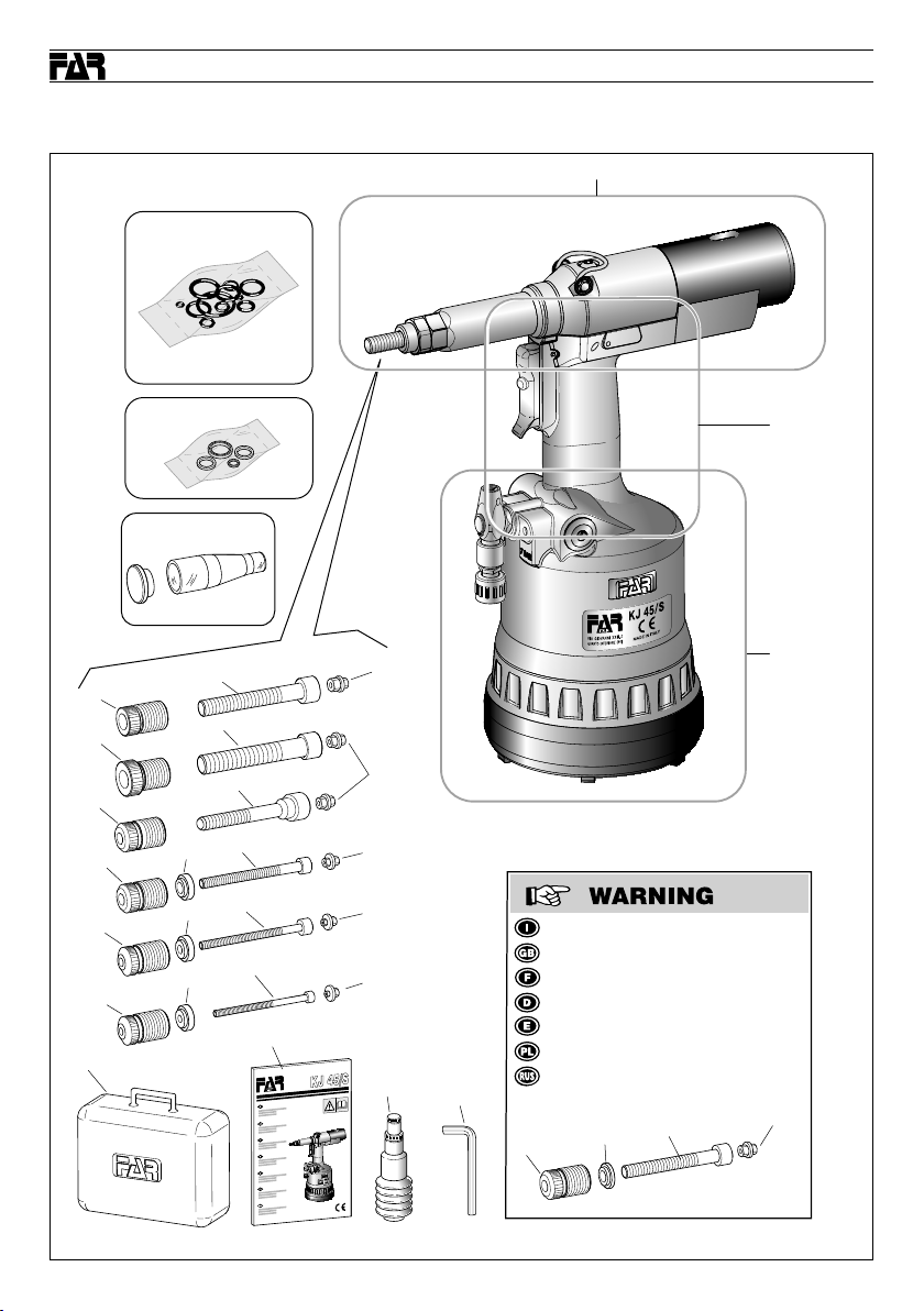
KJ 45/S
Tav. 1/5 • Tab. 1/5 • Tab. 1/5 • Taf. 1/5 • Tab. 1/5 • Tab. 1/5 • Черт. 1/5
KJ 45/S
PARTI DI RICAMBIO • SPARE PARTS • PIECES DETACHEES • ERSATZTEILE • PIEZAS DE REPUESTO • CZĘŚCI ZAMIENNE • ДЕТАЛИ
Tav. 02
KIT A
KIT Q
KIT B
1
4
7
10
14
18
22
2
5
107
12
11
16
15
20
19
23
3
6
13
17
21
24
25
NOTA : è ancora possibile montare :
NOTE : It is still possible to assemble :
NOTE : Vous pouvez toujours monter :
HINWEIS : Es ist noch möglich zu montieren :
NOTA : Se puede todavia montar :
UWAGA : Można jeszcze zamontować :
ПРИМЕЧАНИЕ : Также возможно смонтировать :
9
7
8
Tav. 03
Tav. 04
- M8
6
74 Date 07-2016 Revisione - 08
Page 75

KJ 45/S
KJ 45/S
Tav. 2/5 • Tab. 2/5 • Tab. 2/5 • Taf. 2/5 • Tab. 2/5 • Tab. 2/5 • Черт. 2/5
PARTI DI RICAMBIO • SPARE PARTS • PIECES DETACHEES • ERSATZTEILE • PIEZAS DE REPUESTO • CZĘŚCI ZAMIENNE • ДЕТАЛИ
51
50
37 A
27
26 Q
59 A
39
38 A
49
48
32 A
46
30 A
55
44
29
56 A
31 A
42
35 A
34 Q
28
110 G
53
60 A
58 A
111 G
53
40
47
41
43
33
KIT E
KIT D
KIT C
36
54
KIT F
57
KIT C
Tav. 02
Revisione - 08 Date 07-2016
KIT D
KIT F
KIT E
KIT G
110G(x1)
111G(x1)
75
Page 76

KJ 45/S
Tav. 3/5 • Tab. 3/5 • Tab. 3/5 • Taf. 3/5 • Tab. 3/5 • Tab. 3/5 • Черт. 3/5
KJ 45/S
PARTI DI RICAMBIO • SPARE PARTS • PIECES DETACHEES • ERSATZTEILE • PIEZAS DE REPUESTO • CZĘŚCI ZAMIENNE • ДЕТАЛИ
KIT H
69
68
70
KIT I
70
65
68
109
KIT A
69
KIT A
KIT
61
66
H
KIT
L
M
KIT
64
I
108
KIT
KIT M
63
62
76 Date 07-2016 Revisione - 08
Page 77

KJ 45/S
KJ 45/S
Tav. 4/5 • Tab. 4/5 • Tab. 4/5 • Taf. 4/5 • Tab. 4/5 • Tab. 4/5 • Черт. 4/5
PARTI DI RICAMBIO • SPARE PARTS • PIECES DETACHEES • ERSATZTEILE • PIEZAS DE REPUESTO • CZĘŚCI ZAMIENNE • ДЕТАЛИ
106
104
KIT N
KIT P
103
99
105
76
P
71
100
78
77
KIT
O
83
81
80
79
KIT
70
75
74
73
96
94
93
95
100
82
86
85
102
N
KIT
101
84
Revisione - 08 Date 07-2016
87
90
89
75
91
97
72
88
92
98
77
Page 78

KJ 45/S
Tav. 5/5 • Tab. 5/5 • Tab. 5/5 • Taf. 5/5 • Tab. 5/5 • Tab. 5/5 • Черт. 5/5
KJ 45/S
PARTI DI RICAMBIO • SPARE PARTS • PIECES DETACHEES • ERSATZTEILE • PIEZAS DE REPUESTO • CZĘŚCI ZAMIENNE • ДЕТАЛИ
5
4
3
2
1
10
9
8
7
6
12
8
11
14
13
78 Date 07-2016 Revisione - 08
Page 79

Page 80

L’elenco dei centri di assistenza è disponibile sul Ns. sito
I
web: http://www.far.bo.it ( Organizzazione )
The list of the service centres is available on our website
GB
http://www.far.bo.it ( Organization )
La liste des centres d’assistance est disponible sur notre
F
site internet http://www.far.bo.it ( Organisation )
Die Liste der Reparaturservices ist verfügbar unter unserer
D
Webseite http://www.far.bo.it ( Organisation )
La lista de los servicios postventa es disponible en nuestro
E
sitio web http://www.far.bo.it ( Organización )
Lista punktów serwisowych jest dostępna na naszej stronie internetowej
PL
http://www.far.bo.it ( Organizacja )
Список сервисных центров приведен на нашем веб-сайте
RUS
http://www.far.bo.it ( ОРГАНИЗАЦИЯ )
FASTENING SYSTEMS • SYSTEMES DE FIXATION
VERBINDUNGSSYSTEME • SISTEMAS DE FIJACION
SYSTEMY MOCOWANIA • СИСТЕМЫ КРЕПЛЕНИЯ
SEDE • HEAD OFFICE • SIEGE
HAUPTSITZ • SEDE
SIEDZIBA • ОФИСНЫЙ ЦЕНТР :
40057 Quarto Inferiore - Bologna - Italy
Via Giovanni XXIII, 2
Tel. +39 - 051 6009511
Ufficio Vendite Fax +39 - 051 767443
E-mail: itacom@far.bo.it
Export Dpt. Fax +39 - 051 768284
E-mail: export@far.bo.it
SISTEMI DI FISSAGGIO
DEPOSITO • WAREHOUSE • DEPOT
WARENLAGER • ALMACEN
ODDZIAŁ • СКЛАД :
20099 Sesto San Giovanni
Milano
Italy
Via Archimede, 8
Tel. +39 - 02 2409634
Fax +39 - 02 26222279
E-mail: itacom@far.bo.it
www.far.bo.it
 Loading...