

Fanvil i32V Quick Installation Manual
Video Door Phone
Quick Installation Guide
www.fanvil.com
1
Package Contents
i32V Video Door Phone
Video Door Phone
Quick Installation Guide
Quick Installation Guide
www.fanvil.com
RFID Cards Screw and tool
2
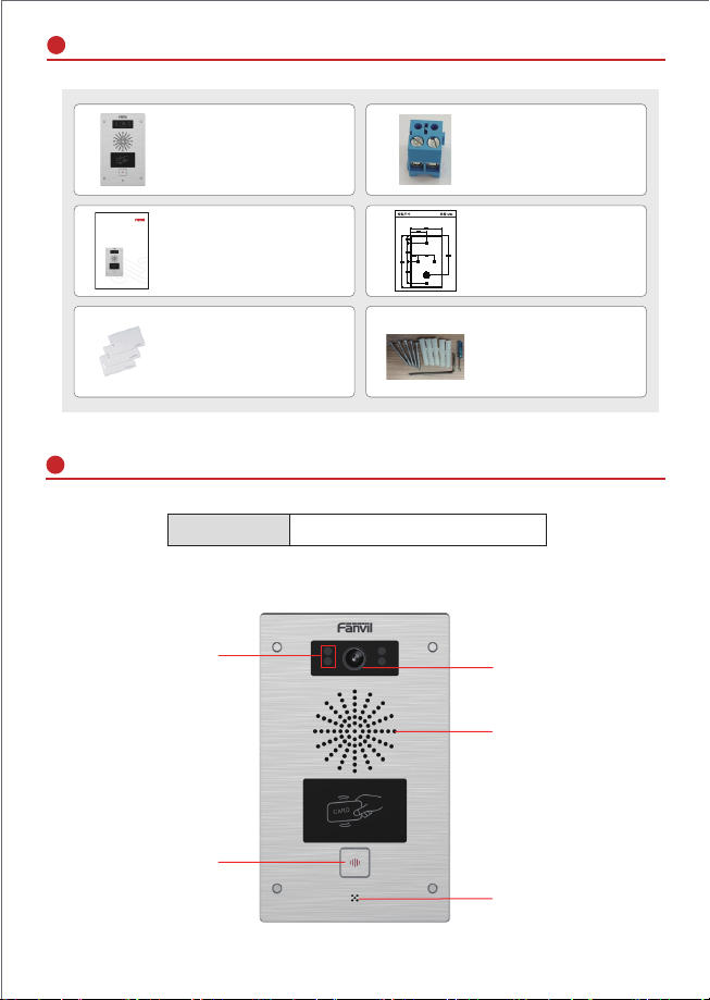
Physical specification
Device size
1) Panel
IR LED
Connector
Mounting Template
195 x 120 x 34 (mm)
Camera
Speaker
RFID area
MIC
1
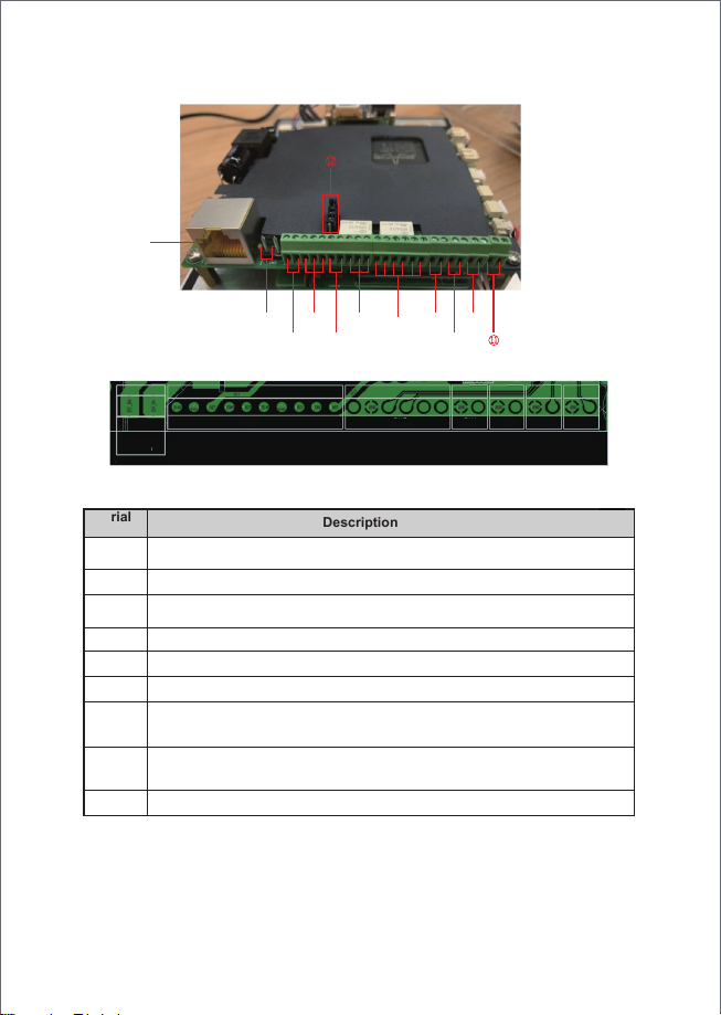
2) Interface description
Open the rear case of the device, there is a row of terminal blocks for connecting the power supply,
electric lock control, etc. The connection is as follows:
①
②③④⑤⑥
CN11 CN2 CN5 CN4 CN3 CN10 CN9
12V+
S1-IN
S1-OUT
12V
NC1
COM1
NO1
S2-IN
S2-OUT
NC2
COM2
Serial
number
JP1 Jumper
There are two modes for power supply of electric-lock as shown in the picture below.
(The default is “ Passive Mode: ”).
Passive Mode: When the electric-lock starting current is more than 12V/500mA, need to use the external
drive mode, the electric lock interface for short circuit output control.
Ethernet interface: standard RJ45 interface, 10/100M adaptive, it is recommended to
1
use five or five types of network cable
Power interface: 12V/1A input left positive, right grounded
2
Two sets of short-circuit input detection interfaces: for connecting switches, infrared probes,
3、5
door magnets, vibration sensors and other input devices
Two sets of short-circuit output control interface: used to control electric locks, alarms, etc.
4、6
7
Wiegand interface
Two sets of door magnetic detection
8、9
Recording output interface: Mix the device and the sound of the far-end call. One is the
recording signal line, and the other is the ground line (be sure to ground the line,
10
otherwise there will be noise)
External active speaker interface: external active speakers for audio power amplification.
11
One is the audio signal line, and the other is the ground line (be sure to ground the line,
otherwise there will be noise)
JP1 jumper
12
Description
⑦
VCC_OUT
NO2
GNDD0D1
⑩
⑧
⑨
LED
Buzzer
GND
DET IN2
GND
MIC_SPK
GND
Line OUT
GND
DET IN1
Line OUT
2
 Loading...