

Fanvil i23 User Manual
[键入文字]
1 / 59
i23
IP Voice Access User Manual
Wall mounted In-wall

[键入文字]
2 / 59
Document VER
Firmware VER
Explanation
Time
V1.0
2.3.1028.434
Initial issue
20151209
V.2.0
2.3.1028.434
Increase the interface parameters, modify the company
address, increase the QIG IP scanning tool download
address
20171027

[键入文字]
3 / 59
Safety Notices
1. Please use the specified power adapter. If you need to use the power adapter provided by other
manufacturers under special circumstances, please make sure that the voltage and current provided is
in accordance with the requirements of this product, meanwhile, please use the safety certificated
products, otherwise may cause fire or get an electric shock.
2. When using this product, please do not damage the power cord either by forcefully twist it, stretch
pull, banding or put it under heavy pressure or between items, otherwise it may cause damage to the
power cord, lead to fire or get an electric shock.
3. Before using, please confirm that the temperature and environment is humidity suitable for the
product to work. (Move the product from air conditioning room to natural temperature, which may
cause this product surface or internal components produce condense water vapor, please open power
use it after waiting for this product is natural drying).
4. Please do not let non-technical staff to remove or repair. Improper repair may cause electric shock,
fire, malfunction, etc. It will lead to injury accident or cause damage to your product.
5. Do not use fingers, pins, wire, other metal objects or foreign body into the vents and gaps. It may
cause current through the metal or foreign body, which may even cause electric shock or injury
accident. If any foreign body or objection falls into the product please stop using.
6. Please do not discard the packing bags or store in places where children could reach, if children trap
his head with it, may cause nose and mouth blocked, and even lead to suffocation.
7. Please use this product with normal usage and operating, in bad posture for a long time to use this
product may affect your health.
8. Please read the above safety notices before installing or using this phone. They are crucial for the safe
and reliable operation of the device.

[键入文字]
4 / 59
Directory
A. PRODUCT INTRODUCTION ............................................................................................................. 6
1. APPEARANCE OF THE PRODUCT .............................................................................................................. 6
2. DESCRIPTION .................................................................................................................................... 7
B. START USING .................................................................................................................................... 8
1. CONFIRM THE CONNECTION .................................................................................................................. 8
1) Power port ................................................................................................................................ 8
2) Electric-lock and indoor switch port ........................................................................................... 8
3) Driving mode of electric-lock(Default in active mode) ................................................................ 8
4) Wiring instructions .................................................................................................................... 9
2. QUICK SETTING ............................................................................................................................... 10
C. BASIC OPERATION .......................................................................................................................... 11
1. ANSWER A CALL .............................................................................................................................. 11
2. CALL ............................................................................................................................................ 11
3. END CALL ....................................................................................................................................... 11
4. CALL RECORD .................................................................................................................................. 11
5. OPEN THE DOOR OPERATION ............................................................................................................... 11
D. PAGE SETTINGS ........................................................................................................................... 12
1. BROWSER CONFIGURATION ................................................................................................................ 12
2. PASSWORD CONFIGURATION .............................................................................................................. 12
3. CONFIGURATION VIA WEB ................................................................................................................. 13
(1) BASIC ................................................................................................................................... 13
a) STATUS ................................................................................................................................. 13
b) WIZARD ............................................................................................................................... 14
c) LANGUAGE ........................................................................................................................... 15
d) TIME&DATE .......................................................................................................................... 15
(2) NETWORK ............................................................................................................................ 17
a) WAN .................................................................................................................................... 17
b) LAN ...................................................................................................................................... 19
c) QoS&VLAN ........................................................................................................................... 19
d) WEB FILTER .......................................................................................................................... 21
e) FIREWALL ............................................................................................................................. 22
f) VPN ...................................................................................................................................... 23
g) SECURITY ............................................................................................................................. 25

[键入文字]
5 / 59
(3) VOIP ..................................................................................................................................... 26
a) SIP ....................................................................................................................................... 26
b) STUN .................................................................................................................................... 29
(4) INTERCOM ........................................................................................................................... 31
a) AUDIO .................................................................................................................................. 31
b) FEATURE .............................................................................................................................. 32
c) MCAST ................................................................................................................................. 34
d) Action URL ........................................................................................................................... 37
(5) DOOR PHONE ....................................................................................................................... 37
a) FUNCTION KEY ..................................................................................................................... 37
b) DOOR PHONE ....................................................................................................................... 40
c) DOOR CARD ......................................................................................................................... 42
d) DOOR ACCESS ...................................................................................................................... 44
e) DOOR LOG ........................................................................................................................... 46
(6) MAINTENANCE ..................................................................................................................... 47
a) AUTO PROVISION ................................................................................................................. 47
b) SYSLOG ................................................................................................................................ 49
c) CONFIG ................................................................................................................................ 50
d) UPDATE ................................................................................................................................ 51
e) ACCESS ................................................................................................................................. 52
f) REBOOT ............................................................................................................................... 52
(7) LOGOUT ............................................................................................................................... 53
E. APPENDIX ...................................................................................................................................... 54
1. TECHNICAL PARAMETERS .................................................................................................................... 54
2. BASIC FUNCTIONS ............................................................................................................................ 55
3. SCHEMATIC DIAGRAM ....................................................................................................................... 55
F. OTHER INSTRUCTIONS .................................................................................................................... 56
1. OPEN DOOR MODES ......................................................................................................................... 56
2. MANAGEMENT OF CARD .................................................................................................................... 57
[键入文字]
6 / 59
A. Product introduction
i23 voice access is a full digital network door phone,with its core part adopts mature VoIP
solution(Broadcom chip), stable and reliable performance, hands-free adopting digital full-duplex
mode, voice loud and clear, generous appearance, solid durable, easy for installation,
comfortable keypad and low power consumption.
i23 voice access supports entrance guard control, voice intercom, ID card and keypad remote to
open the door.
1. Appearance of the product
Wall mounted In-wall
[键入文字]
7 / 59
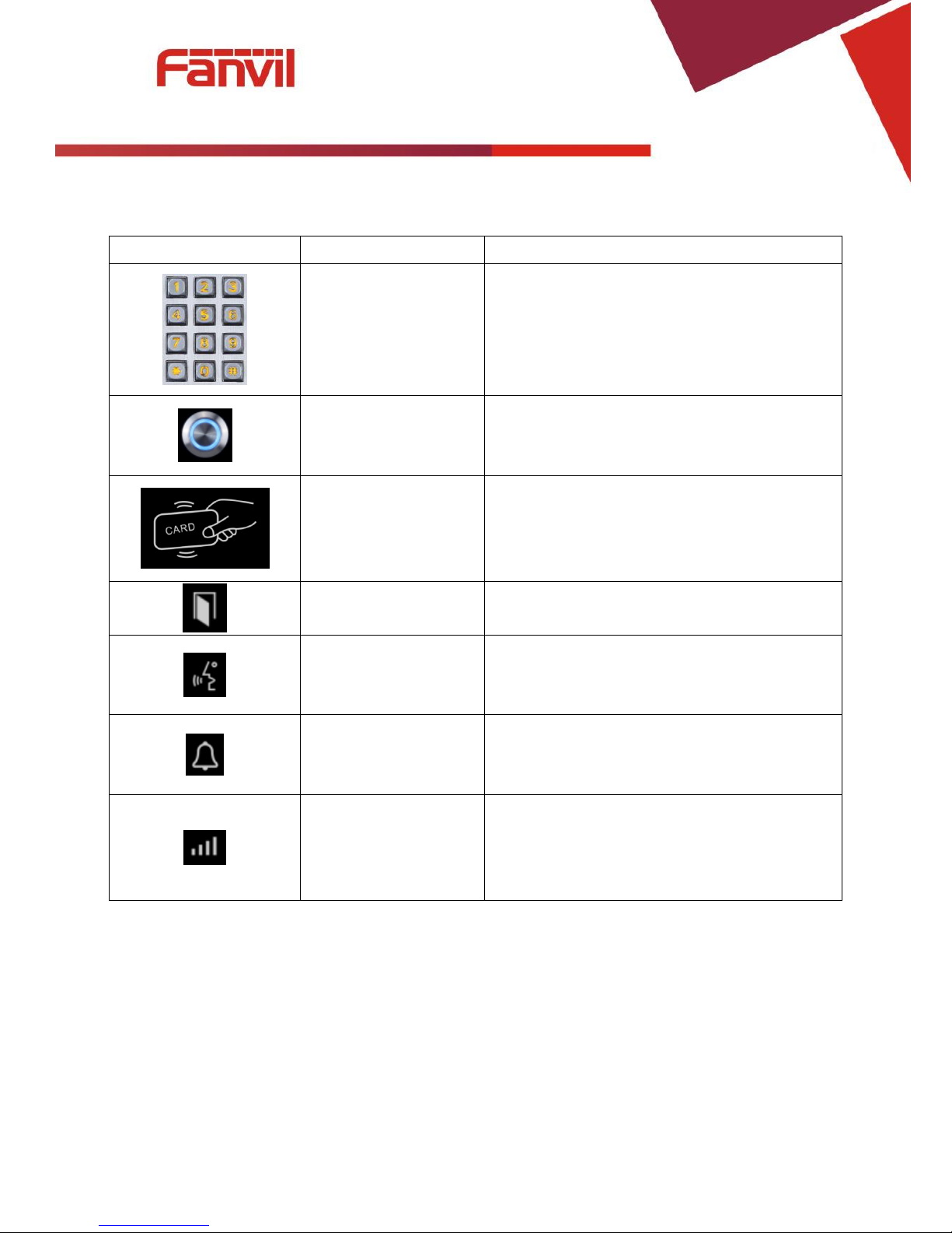
2. description
Buttons and icons
Description
Function
Numeric keyboard
Input password to open the door or to call.
programmable keys
Can be set to a variety of functions, in order to
meet the needs of different occasions
induction zone
RFID induction area
Lock Status
Door unlocking: On
Door locking: Off
Call status
Standby: Off
Hold/Blink with 1s
Calls: On
Ring status
Standby: Off
Ringing: On
Network/SIP
Registration
Network error: Blink with 1s
Network running: Off
Registration failed: Blink with 3s
Registration succeeded: On

[键入文字]
8 / 59
B. Start Using
Before you start to use the equipment, please make the following installation:
1. Confirm the connection
Confirm whether the equipment of the power cord, network cable, electric lock control line
connection and the boot-up is normal. (Check the network state of light)
1) Power port
Power supply ways: 12v/DC or POE.
CN1
1 2 +12V
GND
12V 1A/DC
2) Electric-lock and indoor switch port
J2
1 2 3 4 5
S_IN
S_OUT
NC
COM
NO
Indoor switch
Electric-lock switch
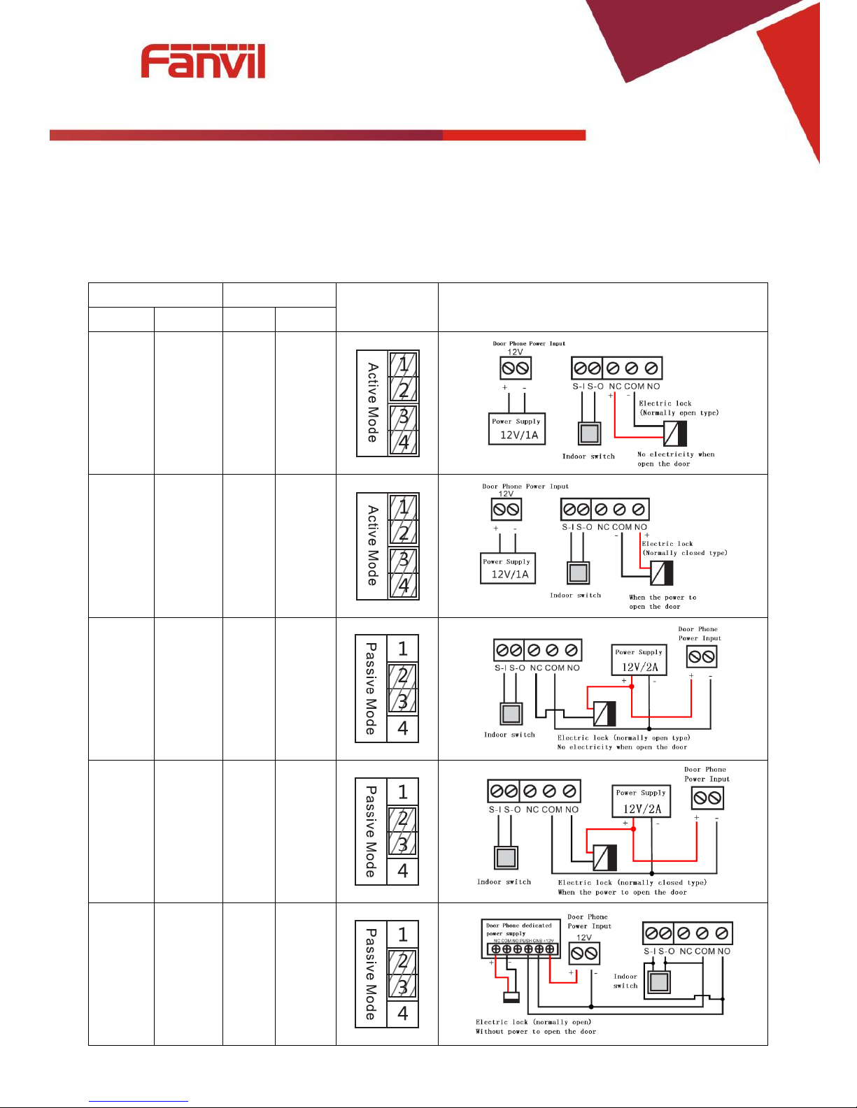
3) Driving mode of electric-lock(Default in active mode)
【Note】When the device is in active mode, it can drive 12V/700mA switch output maximum, to which a
standard electric-lock or another compatible electrical appliance can be connected.
When using the active mode, it is 12V DC in output.
When using the passive mode, output is short control (normally open mode or normally close mode).
Jumper in passive mode
Jumper in active mode
[键入文字]
9 / 59
4) Wiring instructions
NO: Normally Open Contact.
COM: Common Contact.
NC: Normally Close Contact.
Driving Mode
Electric lock
Jumper port
Connections
Active
Passive
NO
NC
√ √
√
√
√ √
√
√
√ √

[键入文字]
10 / 59
2. Quick Setting
The product provides a complete function and parameter setting.Users may need to have the
network and SIP protocol knowledge to understand the meaning represented by all parameters. In
order to let equipment users enjoy the high quality of voice service and low cost advantage brought by
the device immediately, here we list some basic but compulsory setting options in this section to let
users know how to operate without understanding such complex SIP protocols.
In prior to this step, please make sure your broadband Internet online can be normal operated,
and complete the connection of the network hardware. The product factory default network mode is
DHCP. Thus, only connect equipment with DHCP network environment that network can be
automatically connected.
Press and hold “#” key for 3 seconds and the door phone will report the IP address by voice, or use
the "iDoorPhoneNetworkScanner.exe " software to find the IP address of the device.
(Download address http://download.fanvil.com/tool/iDoorPhoneNetworkScanner.exe )
Note: when power on, 30s waiting is needed for device running.
Log on to the WEB device configuration.
In a SIP page configuration service account, user name, parameters that are required for server
address register.
You can set DSS key in the Webpage(functions key settings -> function key).
You can set function parameters in the Webpage (Intercom-> feature).

[键入文字]
11 / 59
C. Basic operation
1. Answer a call
When a call comes in, the device will answer automatically. If you cancel auto answer feature and set
auto answer time, you will hear the bell ring at the set time and the device will auto answer after a
timeout.
2. Call
Configure shortcut key as hot key and setup a number, then press shortcut key can call the
configured number.
3. End call
Enable Release key hang up to end call.
4. Call record
The device provides 900 call records. When the storage space is exhausted, it will cover the first call
records. When the device is powered down or reboot, call records will be removed.
You can view the call records in the web page (Door phone/Door log)
5. Open the door operation
Through the following seven ways to open the door:
1) Input password on the keyboard to open the door.
2) Access to call the owner and the owner enter the remote password to open the door.
3) Owner/other equipment call the access control and enter the access code to open the door. (access
code should be included in the list of access configuration, and enable for remote calls to open the
door )
4) Swipe the RFID cards to open the door.
5) By means of indoor switch to open the door.
6) Private access code to open the door.
Enable for local authentication, and set private access code. Input the access code directly under
standby mode to open the door. In this way, the door log will record corresponding card number
and user name.
7) Active URL control command to open the door.
URL is “http://host/cgi-bin/ConfigManApp.com?key=F_LOCK&code=openCode”, “openCode” is the
remote control code to open the door.
[键入文字]
12 / 59
If access code is input correctly, the device will play sirens sound to prompt access control and the
remote user, while input error by low-frequency short chirp.
Password input successfully followed by high-frequency sirens sound, while input error is followed
by high-frequency short chirp.
When door has been opened, the device will play sirens sound to prompt.
D. Page settings
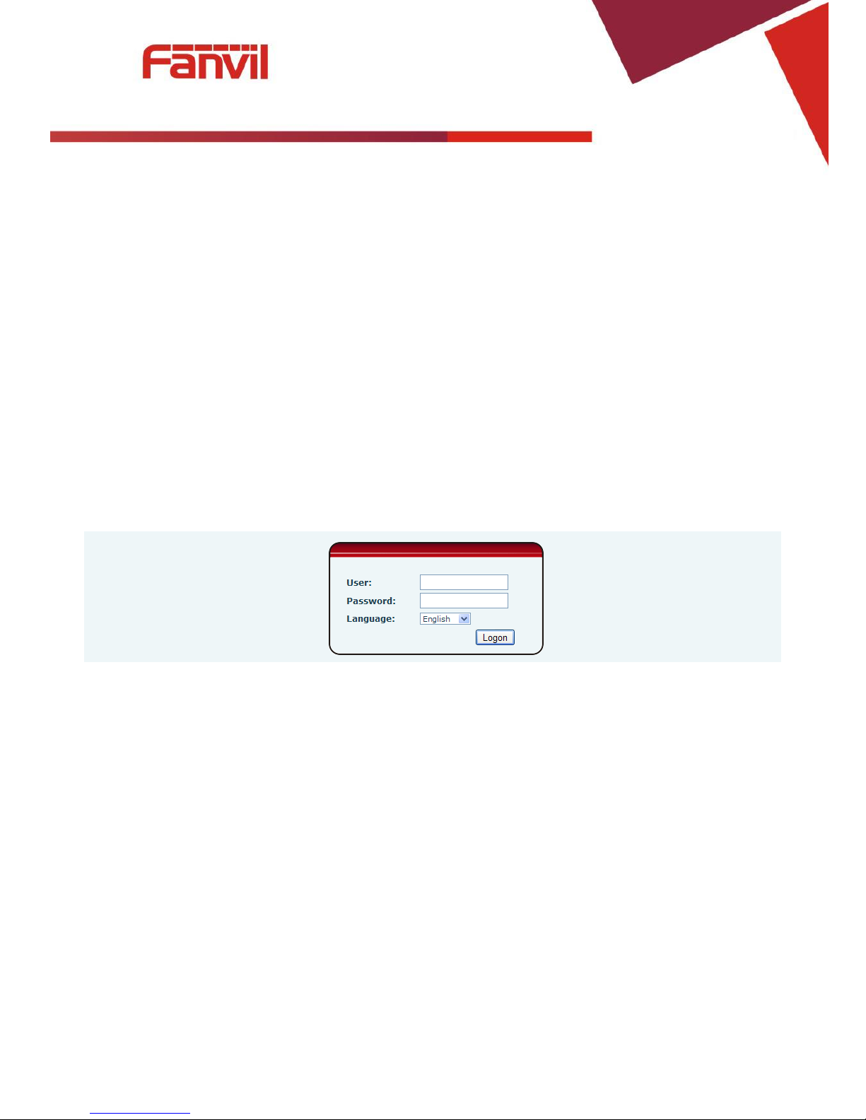
1. Browser configuration
When the device and your computer are successfully connected to the network, enter the IP address
of the device on the browser as http://xxx.xxx.xxx.xxx/ and you can see the login interface of the web page
management.
Enter the user name and password and click the [logon] button to enter the settings screen.
After configuring the equipment, remember to click SAVE under the Maintenance tab. If this is not
done, the equipment will lose the modifications when it has been rebooted.
2. Password Configuration
There are two levels of access: root level and general level. A user with root level access can browse
and set all configuration parameters, while a user with general level can set all configuration parameters
except server parameters for SIP.
Default user with general level:
Username: guest
Password: guest
Default user with root level:
Username: admin
Password: admin
[键入文字]
13 / 59
3. Configuration via WEB
(1) BASIC
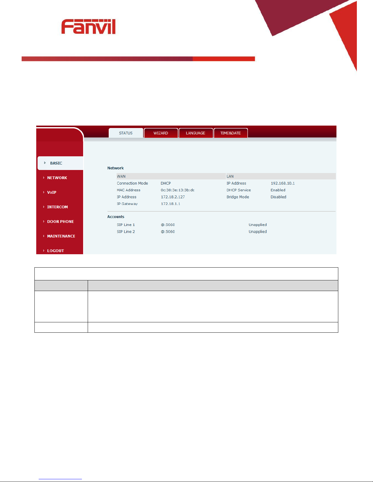
a) STATUS
Status
Field Name
Explanation
Network
Shows the configuration information for WAN and LAN port, including connection
mode of WAN port (Static, DHCP, PPPoE),MAC address, IP address of WAN port and LAN
port, DHCP server, status for LAN port (ENABLED or DISABLED).
Accounts
Shows the phone numbers and registration status for the 2 SIP LINES.
[键入文字]
14 / 59
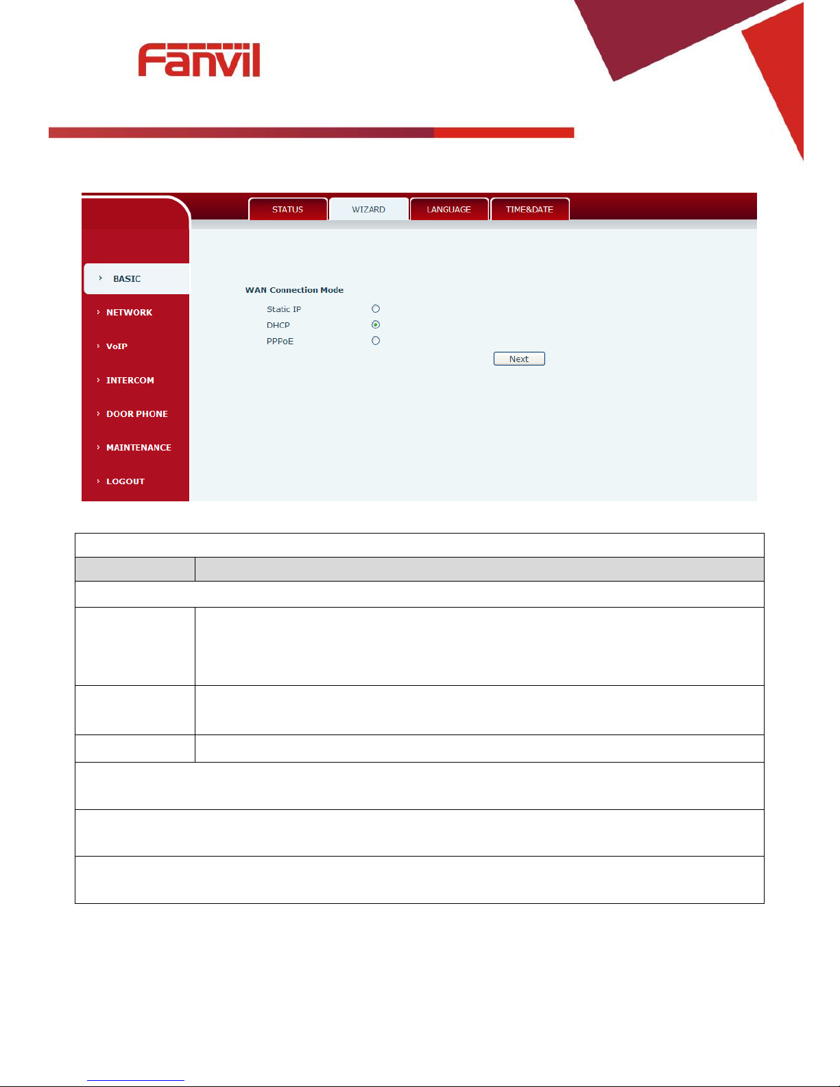
b) WIZARD
Wizard
Field Name
Explanation
Select the appropriate network mode. The equipment supports three network modes:
Static IP mode
The parameters of a Static IP connection must be provided by your ISP.
DHCP mode
In this mode, network parameter information will be obtained automatically from a
DHCP server.
PPPoE mode
In this mode, you must enter your ADSL account and password.
Static IP mode is selected; Click <Next> to go to Quick SIP Settings, Click Back to return to the Wizard
screen.
After selecting DHCP and clicking NEXT, the Quick SIP Settings screen will appear. Click Back to return to
the Wizard screen. Click <Next> to go to the Summary screen.
If PPPoE is selected, this screen will appear. Enter the information provided by the ISP. Click <Next> to go
to Quick SIP Setting. Click Back to return to the Wizard screen.
[键入文字]
15 / 59
c) LANGUAGE
Set the current language.
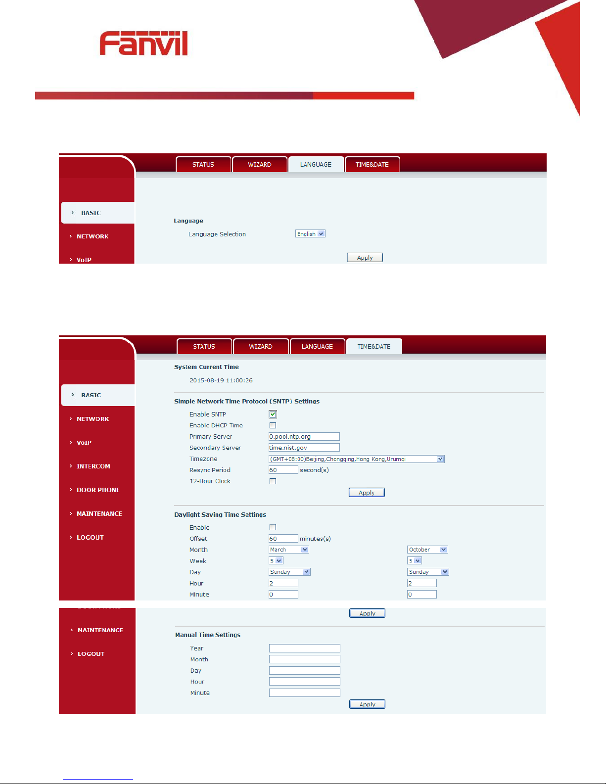
d) TIME&DATE
Set the time zone and SNTP (Simple Network T ime Protocol) server on this page. Daylight Saving
Time configuration and Manual Time and Date entry can also be done in this page.

[键入文字]
16 / 59
Time&Date
Field Name
Explanation
System Current Time
Display the current time
Simple Network Time Protocol (SNTP) Settings
Enable SNTP
Enable or Disable SNTP
Enable DHCP
Time
If this is enabled, equipment will synchronize time with DHCP server
Primary Server
IP address of Primary SNTP Server
Secondary
Server
IP address of Secondary SNTP Server
Time zone
Local Time Zone
Resync Period
Time between resync to SNTP server. Default is 60 seconds.
12-Hour Clock
If checked, clock is 12 hour mode. If unchecked, 24 hour mode. Default is 24 hour
mode.
Daylight Saving Time Settings
Enable
Enable daylight saving time
Offset
DST offset. Default is 60 minutes
Month
Start and end month for DST
Week
Start and end week for DST
Day
Start and end day for DST
Hour
Start and end hour for DST
Minute
Start and end minute for DST
Manual Time Settings
Enter the values for the current year, month, day, hour and minute. All values are required.
Be sure to disable SNTP service before entering manual time and date.
[键入文字]
17 / 59
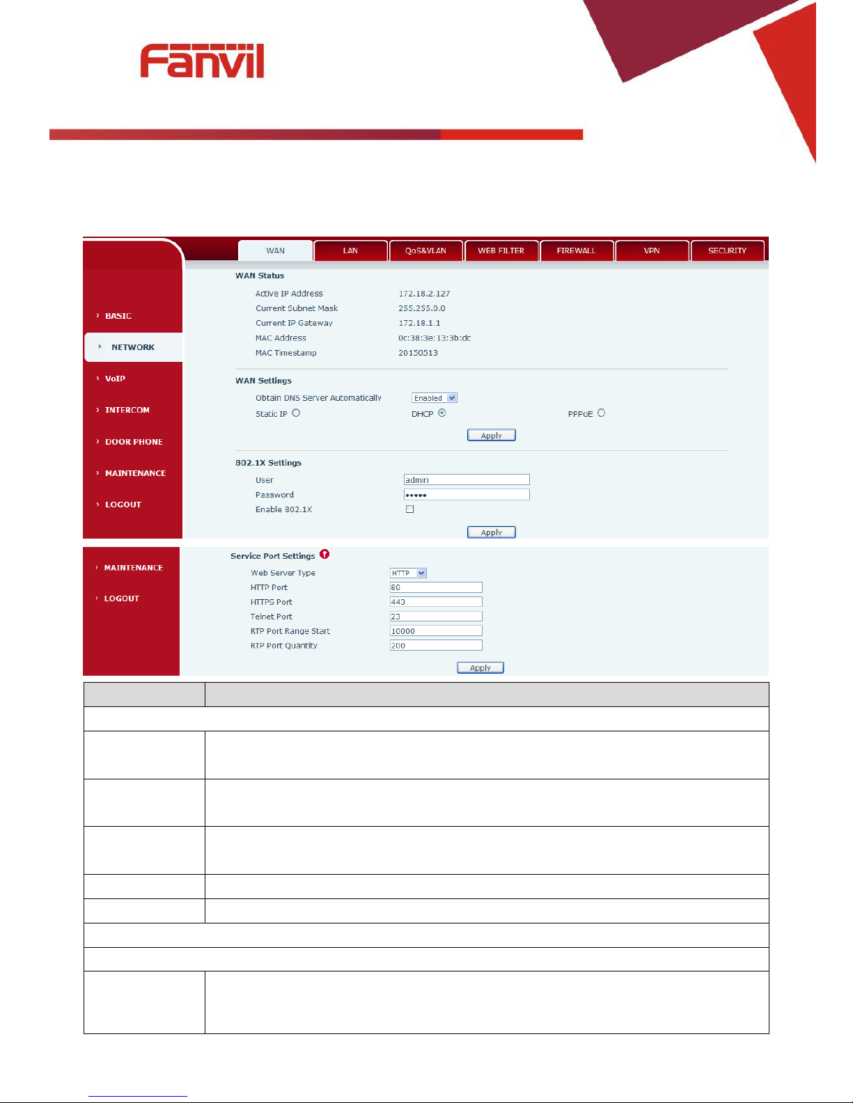
(2) NETWORK
a) WAN
Field Name
Explanation
WAN Status
Active IP
address
The current IP address of the equipment
Current subnet
mask
The current Subnet Mask
Current IP
gateway
The current Gateway IP address
MAC address
The MAC address of the equipment
MAC Timestamp
Get the MAC address of time.
WAN Settings
Select the appropriate network mode. The equipment supports three network modes:
Static
Network parameters must be entered manually and will not change. All parameters
are provided by the ISP.
[键入文字]
18 / 59
Field Name
Explanation
DHCP
Network parameters are provided automatically by a DHCP server.
PPPoE
Account and Password must be input manually. These are provided by your ISP.
If Static IP is chosen, the screen below will appear. Enter values provided by the ISP.
After entering the new settings, click the APPLY button. The equipment will save the new settings and
apply them. If a new IP address was entered for the equipment, it must be used to login to the phone
after clicking the APPLY button.
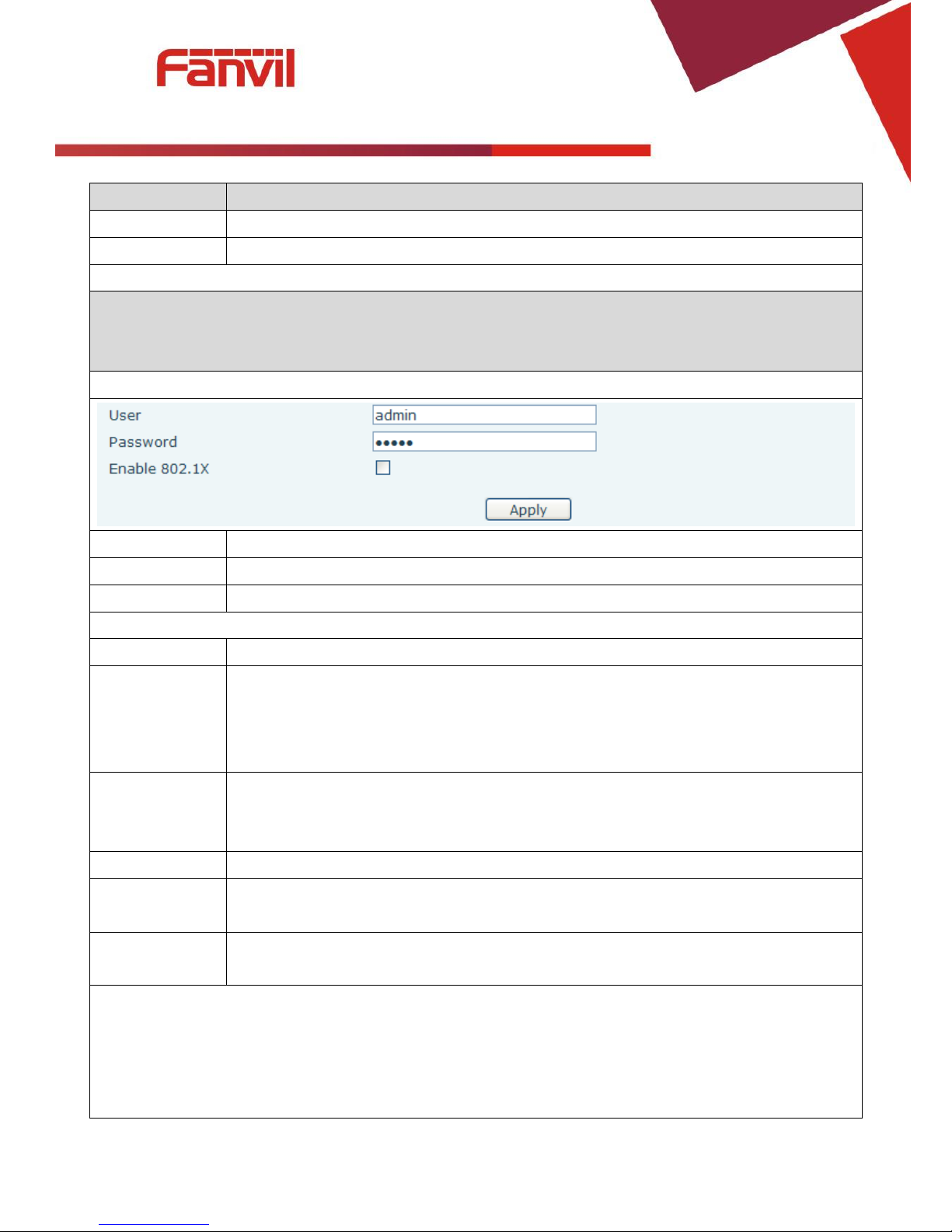
802.1X Settings
User
802.1X user account
Password
802.1X password
Enable 812.1X
Enable or Disable 812.1X
Service port Settings
Web Server Type
Specify Web Server Type – HTTP or HTTPS
HTTP Port
Port for web browser access. Default value is 80. To enhance security, change this from
the default. Setting this port to 0 will disable HTTP access.
Example: The IP address is 192.168.1.70 and the port value is 8090, the accessing
address is http://192.168.1.70:8090.
HTTPS Port
Port for HTTPS access. Before using HTTPS, an HTTPS authentication certification must
be downloaded into the equipment.
Default value is 443. To enhance security, change this from the default.
Telnet Port
Port for Telnet access. The default is 23.
RTP Port Range
Start
Set the beginning value for RTP Ports. Ports are dynamically allocated.
RTP Port
Quantity
Set the maximum quantity of RTP Ports. The default is 200.
Note:
1. Any changes made on this page require a reboot to become active.
2. It is suggested that changes to HTTP Port and Telnet ports be values greater than 1024.Values less
than 1024 are reserved.
3. If the HTTP port is set to 0, HTTP service will be disabled.
 Loading...