

Fanvil i21, i21T User Manual
i21 i21T
I21/I21T Door Phone
User Manual

2
Safety Notices
1. Please use the specified power adapter. If special circumstances need to use the power adapter
provided by other manufacturers,please make sure the voltage and current provided in accordance
with the requirements of this product, meanwhile, please use the safety certificated products,
otherwise may cause fire or get an electric shock.When using this product, please do not damage
the power cord,or forcefully twist it、Stretch pull or banding, and not to be under heavy pressure or
between items, Otherwise may cause the power cord damage, thus lead to fire or get an electric
shock.
2. Before use, please confirm the temperature and environment humidity suitable for the product
work.(Move the product from air conditioning room to natural temperature, which may cause this
product surface or internal components produce condense water vapor, please open power use it
after waiting for this product is natural drying.)
3.Non-technical staff not remove or repair, improper repair or may cause electric shock, fire or
malfunction, etc,Which can lead to injury accident, and also can cause your product damage.
4. Do not use fingers, pins, wire and other metal objects, foreign body into the vents and gaps. It
may cause current through the metal or foreign body,which even cause cause electric shock and
injury accident. If any foreign body or objection fall into the product please stop usage.
5. Please do not discard the packing bags or stored in places where children could reach,if children
trap his head with it,may cause nose and mouth blocked,and even lead to suffocation.
6. Please use this product with normal usage and operating,in bad posture for a long time to use
this product may affect your health.
7. Please read the above safety notices before installing or using this phone. They are crucial for
the safe and reliable operation of the device.

3
Table of Content
1. Acquaint I21/I21T ................................................. 5
1.1. I21/I21T Front ......................................................................................................................................................... 5
1.2. Key Description ....................................................................................................................................................... 5
2. Start Using ....................................................... 5
2.1. Connect the power supply and the network .................................................................................................. 5
2.1.1. Connect Network ....................................................................................................................................... 5
2.1.2、Interface Description ............................................................................................................................... 6
2.1.2.1 Network, Power Switch, Electric Lock Connection ........................................................................ 6
2.1.2.2 Reserve function connection ............................................................................................................... 8
2.1.2.3 Electric Lock Connection Driver Option ........................................................................................... 8
2.1.2.4 Wiring ................................................................................................................................................... 9
2.2. Quick Setting ........................................................................................................................................................ 10
3. I21/I21T Door Phone Basic Operation ............................. 11
3.1. Answering a Call ................................................................................................................................................. 11
3.3. End a Call .............................................................................................................................................................. 12
3.5. Door Open Operation ......................................................................................................................................... 12
4. Page Configuration .............................................. 12
4.1. Ways to configure ............................................................................................................................................... 12
4.1.1.Ways to configure ..................................................................................................................................... 12
4.1.2. Password Configuration ........................................................................................................................ 12
4.2. Setting via web browser .................................................................................................................................... 13
4.3. WEB Page Functional Explanation ................................................................................................................ 13
4.3.1. BASIC .......................................................................................................................................................... 13
4.3.1.1. Status .............................................................................................................................................. 13
4.3.1.2. Wizard .............................................................................................................................................. 14
4.3.1.3. Call Log ........................................................................................................................................... 17
4.3.2. Network ...................................................................................................................................................... 17
4.3.2.1. WAN Config ................................................................................................................................... 17
4.3.2.2. Qos Config ..................................................................................................................................... 19
4.3.2.3. Service Port ................................................................................................................................... 21
4.3.2.4. TIME&DATE ................................................................................................................................... 22
4.3.3. VOIP ............................................................................................................................................................ 24
4.3.3.1. SIP Config ....................................................................................................................................... 24
4.3.3.2. Stun Config .................................................................................................................................... 30
4.3.5. FUNCTION KEY ................................................................................................................................... 30
4.3.5.1. Function key ............................................................................................................................... 30
4.3.5.2. Door Card Setting ...................................................................................................................... 34
4.3.5.3. Call Log ........................................................................................................................................ 35
5. Appendix ....................................................... 35
5.1.1.Specifications: ........................................................................................................................................... 36
5.1.2. Basic Feature ............................................................................................................................................ 36
5.1.3. Schematic Diagram ................................................................................................................................... 37
5.2、Owner Remote Opens the Voice Access Controller by VOIP Phone ................................................... 37
5.3、Card Management ............................................................................................................................................. 37
5.3.1 Issue Card Management ........................................................................................................................... 37

4
5.3.2Issue User Card ........................................................................................................................................... 38
5.3.3 Delete the user card (Method 1): .............................................................................................................. 39
5.3.4、Add Remote Visit Data .......................................................................................................................... 40
5
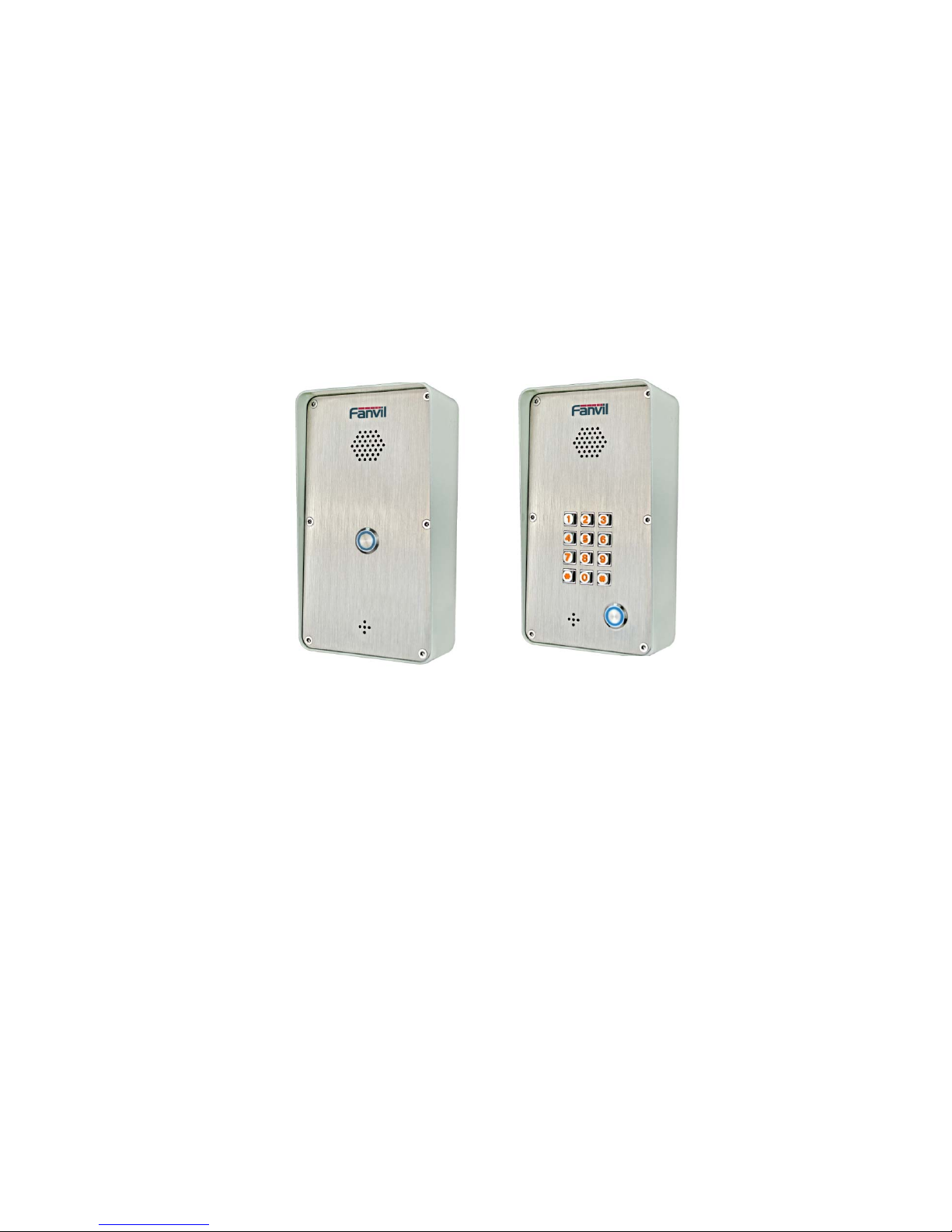
1. Acquaint I21/I21T
Voice Intercom I21/I21T voice entrance guard is a full digital network door phone,its core part adopt Fanvil
mature Voip solution(Broadcom1190 chipset), stable and reliable performance, Hands-free adopting digital
full-duplex mode,Voice loud and clear;generous appearance, solid durable, easy for installation, comfortable
keypad, low power consumption.
I21/I21T voice entrance guard support entrance guard control、Voice Intercom、keypad remote to open the
door.
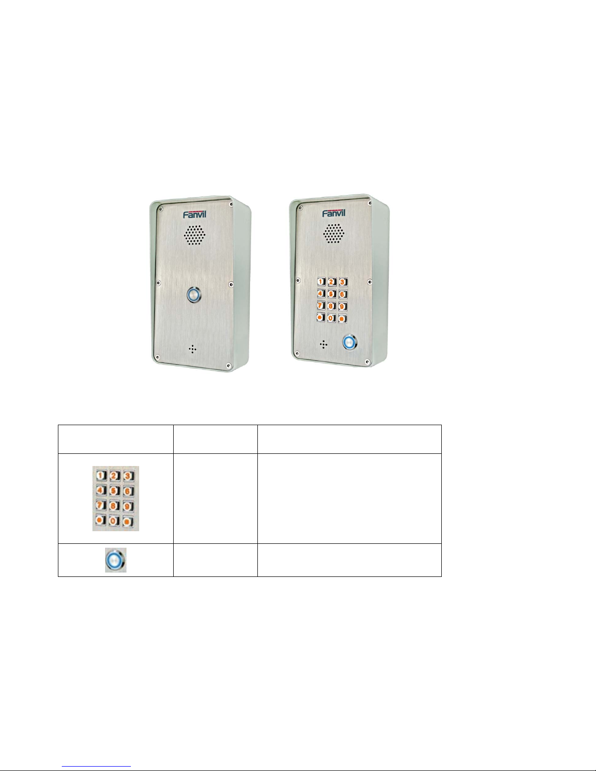
1.1. I21/I21T Front
i21 i21T
1.2.
Key Description
Key Chinese
Specification
Function
digit keyboard
enter the password to open the door
Or make a calling
Programmable
keyboard
Can be set to a variety of functions,to
meet the needs of different occasions
2. Start Using
Before you start to use I21/I21T,please make the following installation:
2.1. Connect the power supply and the network
2.1.1. Connect Network
In prior to this step, please check if your network can work normally and have capacity
of broadband internet access.
1. Broadband Router
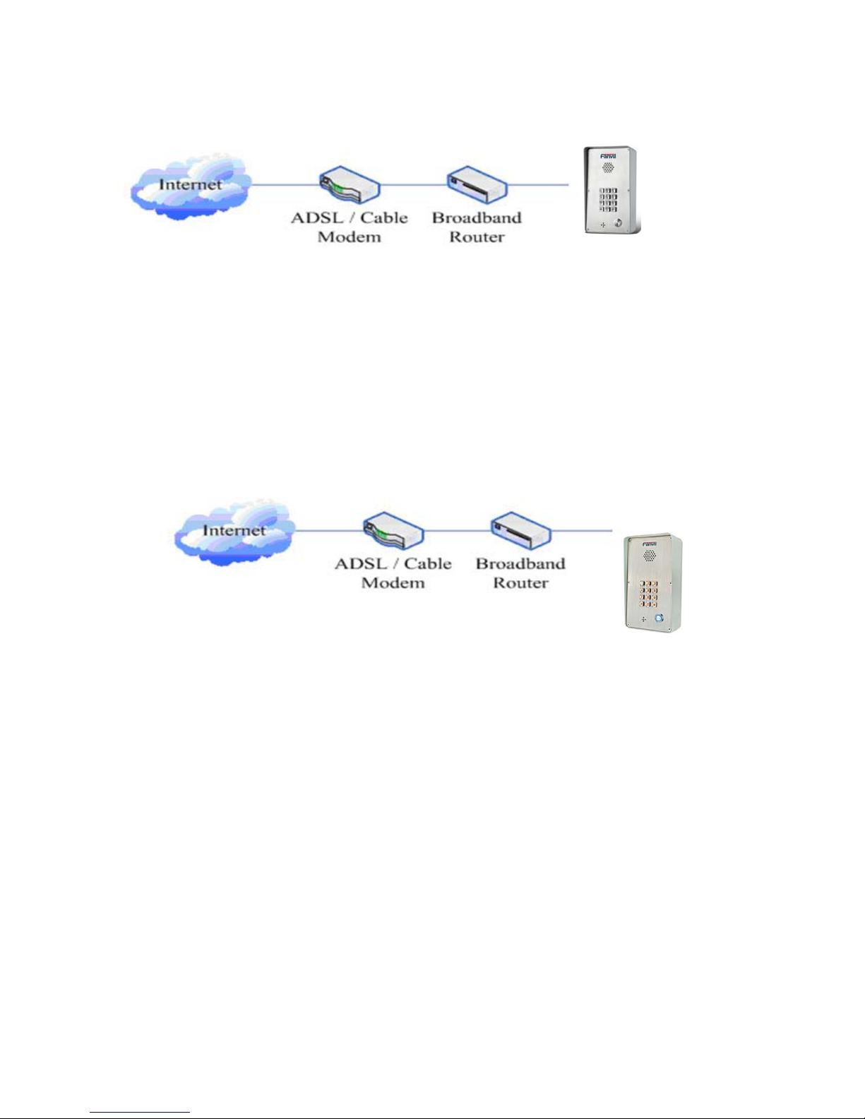
6
Connect network one end with I21/I21T WAN port,connect the other end with your broadband
router LAN port,then network hardware connection is completed. In most cases,you must set your
I21/I21T network as DHCP mode.Please refer to the detailed setting ways 3.2.1, set network.
2. wireless broadband router
Connect network one end with I21/I21T WAN port,connect the other end with your ADSL
modem
LAN port,then network hardware connection is completed. In most cases,If you are using the
TV cable broadband,you must set your I21/I21T network as DHCP mode:if you are using ADSL,
then you must set your I21/I21T network as PPPoE mode.Please refer to the detailed setting ways
2.1.2, set network.
2.1.2、Interface Description
2.1.2.1
Network, Power Switch, Electric Lock Connection
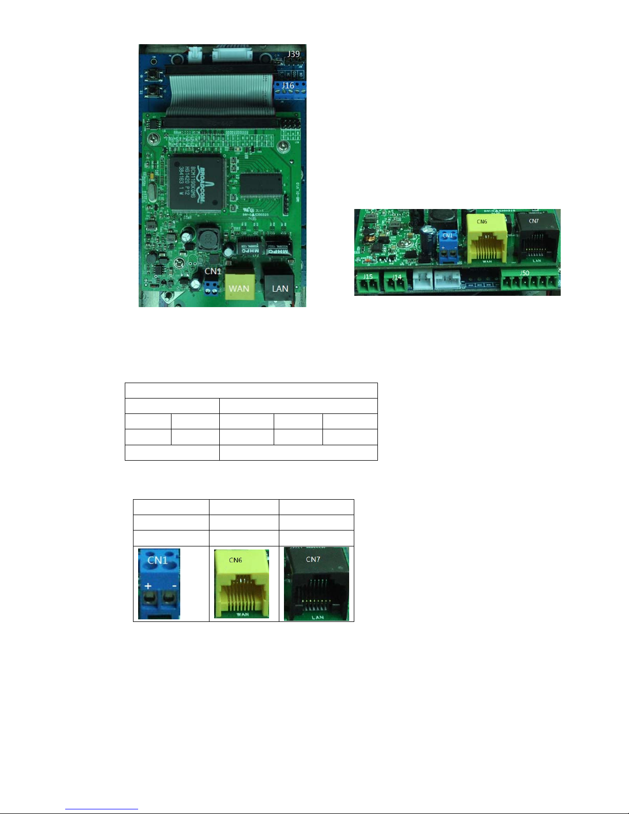
7
I21/I21T connection
(1) Electric LOCK and indoor switch connection
(2) Power supply and Network connection
J16
Indoor switch Electric Lock Driver
1 2 3 4 5
S_IN S_OUT NC COM NO
Connect to the switch
Normally open, normally close port
CN1 CN6 CN7
Power supply WAN port LAN port
12V DC WAN LAN
CN7
8
2.1.2.2 Reserve function connection
Description of Connectors
PIN Function Remark
J15 Audio Output interface. Use to connect the external Audio PA
J14 Use to indicate the call status
IO30A: Output high level when Ringing or talking; Output low level On the other status.
IO30B: Output low level when Ringing or talking; Output high level On the other status.
J50 Tow input detect ports(IN1 and IN2);tow Output ports(OUT1 and OUT2)
Reserve function connection
J15 J14 J50
Audio Output Status
Indicate
Reserve Groud
Input
Port 2
Input
Port 1
Output
Port 2
Output
Port 1
1 2 1 2 1 2 3 4 5 6
SPK- SPK+ IO30B IO30A IO10 GND IN2 IN1 OUT2 OUT1
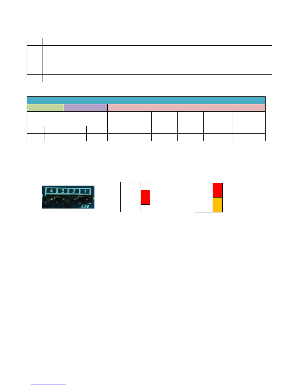
2.1.2.3 Electric Lock Connection Driver Option
【Notice】
When the initial electric current of the lock is less than 500mA/12V, you can access
to the internal driven mode and use the POE of the Voice Access System or 12V DC to
control the the switch of the electric lock ; When the initial electric current of the lock is more
than 500mA/12V, you need to access to the external driven mode(Use specialized DC
power to control the electric lock )
JP39
Outside
Driver
1
2
3
4
External Power Driving
JP39
Inside
Driver
1
2
3
4
Internal Power Driving
9
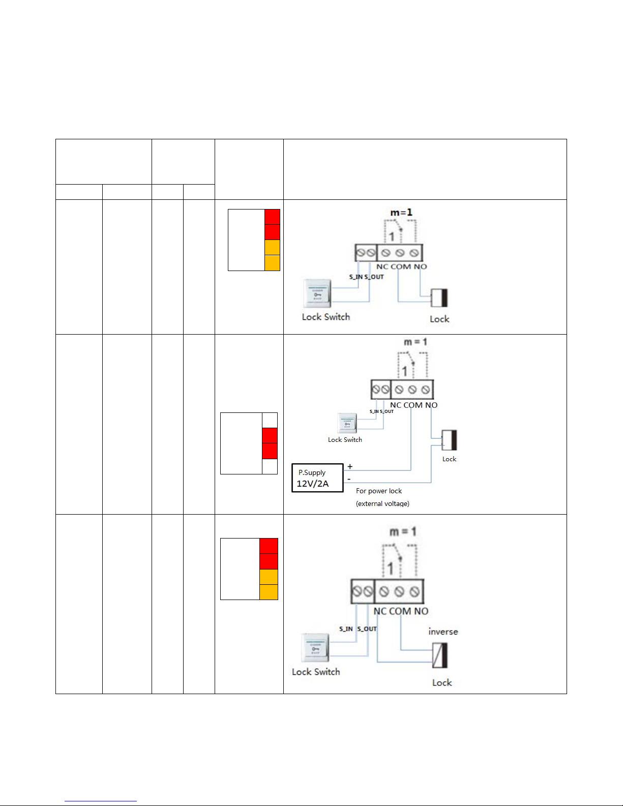
2.1.2.4 Wiring
Relay connection description:
NO:meansidle‐disconnectedcontact(normallyopen)
COM:meansapincontact(middle);
NC:meansanidle‐connectedcontact(normallyclose);
Electric lock
power supply
mode
Electric
lock
Jumper
JP39
Mode of connection
Internal External NO NC
√
√
Inside
Driver
1
2
3
4
√
√
Outside
Driver
1
2
3
4
√
√
Inside
Driver
1
2
3
4
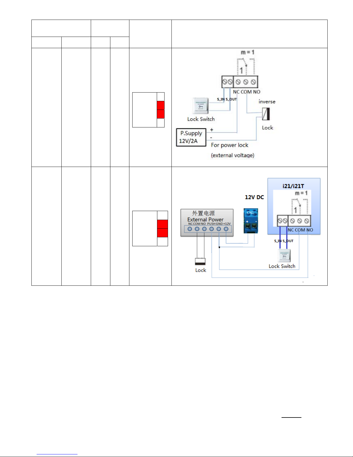
10
Electric lock power
supply mode
Electric
lock
Jumper
JP39
mode of connection
Internal External NO NC
√
√
Outside
Driver
1
2
3
4
√
√
Outside
Driver
1
2
3
4
2.2. Quick Setting
I21/I21T Provide a complete function and parameter setting,users may need to have the network
and SIP protocol knowledge for understanding the meaning represented by all parameters.In order
to let I21/I21T users can quickly enjoy the high quality speech brought by the IP Phone services
and low cost advantage, we especially lists the basic and must set options in this section,which let
users can real-time started without understanding complex SIP protocols.
In prior to this step,please make sure your broadband Internet online can be normal operation,and complete the
connection of the network hardware. I21/I21T factory default network mode is DHCP. Thus,only
connect I21/I21T with DHCP network environment then network can be automatically connected.
1. Long press # keypad 5 Sec,then waiting for the phone play the IP address;or use
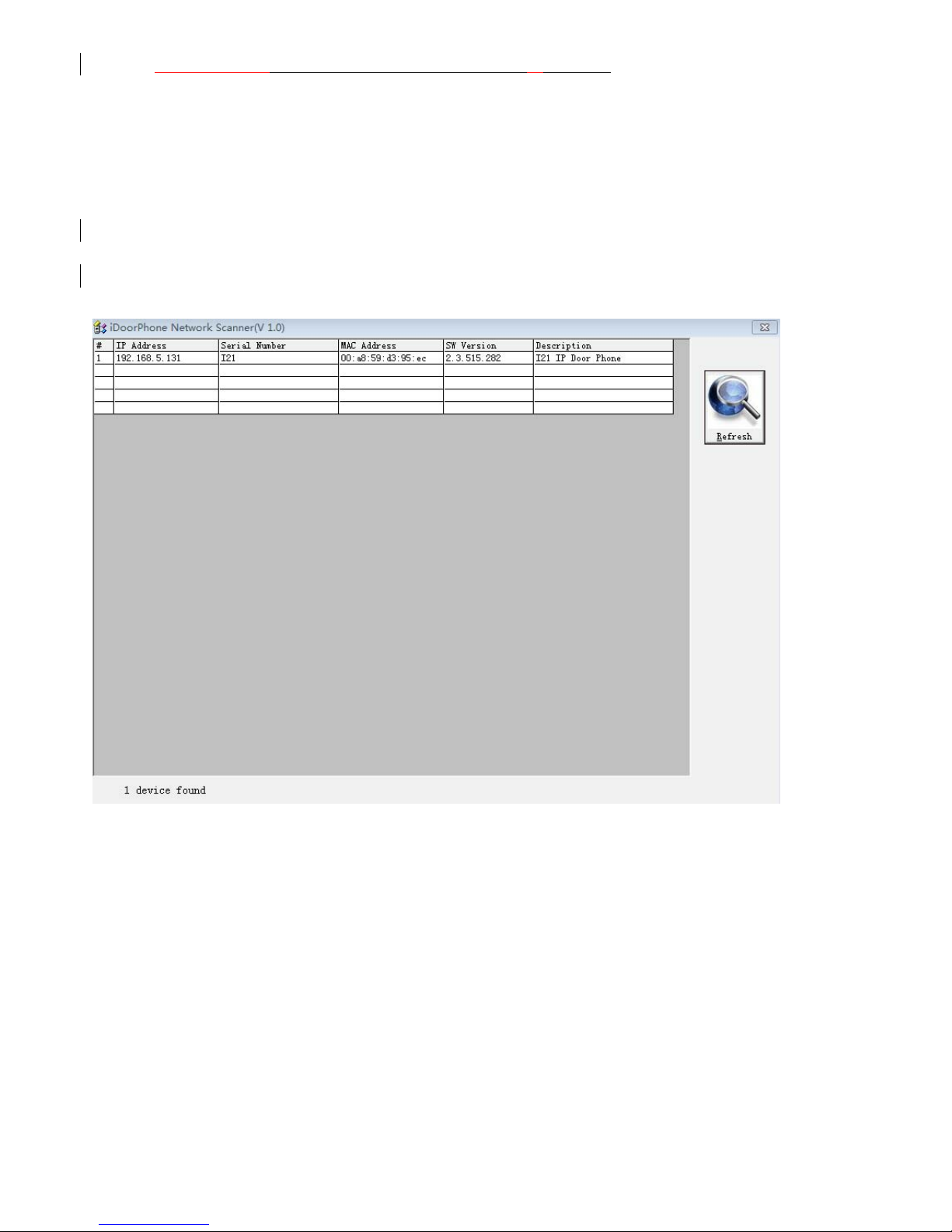
11
iDoorPhoneNetwork.exe software to search the IP address
2. Use IP address log onto WEB server to configurate.
3. Configurate service provider supplied account on SIP page,user name,service address
and other Registration required parameters.
4. Configurate shortcut key on EGS->Function key page.The advice is set to KEY EVENT type,
value is OK keyboard.
5.Configurate Door Phone parameter on EGS->EGS page frame.
3. I21/I21T Door Phone Basic Operation
3.1. Answering a Call
When calling come,I21/I21T will ring,and configurate the shortcut as OK, then can press
shortcut and answer the call.
3.2. Making a Call
Speed Dial
Configurate shortcut as Memory key and setup a number, then press shortcut can call the
configured number immediately.
Keypad Dialing
Configurate shortcut as Dial key. Input wanted number on the keyboard then press short to call.

12
3.3. End a Call
Configurate shortcut as Release key to end the call.
3.4. Call Records
I21/I21T provides 100 missed calls、received calls、dialed Calls records,When the storage
space used up,then will update the earnest records. Then the phone power of or reboot,all the call
records will disappear.
Can check all these three type call records on WEB-Basic->call log page
3.5. Door Open Operation
Through the following four ways to open the door:
1. Input the local password on the keyboard to open the door.
2. The door phone call the owner,the owner enter the remote password to open the door.
3. Owner/other phone call the door,then enter the access code and remote password to open the door.
4. Use RFID to open the door.
The access code input errors by low frequency short chirp prompt to door phone and remote user.
input error will be prompted by low-frequency sirens sound.
Password input error is prompted by high frequency chirp,input successfully will be prompted by
high-frequency sirens sound.
When the door opens by playing intermittent beeps for prompt. Timeout after closing door the prompt will be
stoped.
4. Page Configuration
4.1.
Ways to configure
4.1.1.Ways to configure
I21/I21T has two different ways to different users.:
Use web browser (recommendatory way).
Use telnet with CLI command.
4.1.2. Password Configuration
There are two levels to access to phone: root level and general level. User with
root level can browse and set all configuration parameters, while user with
general level can set all configuration parameters except SIP (1-2) or IAX2’s
that some parameters cannot be changed, such as server address and port. User
will has different access level with different username and password.
Manager mode:
User Name:guest
Password:guest
13
Manager mode:
User Name:admin
Password :admin
4.2. Setting via web browser
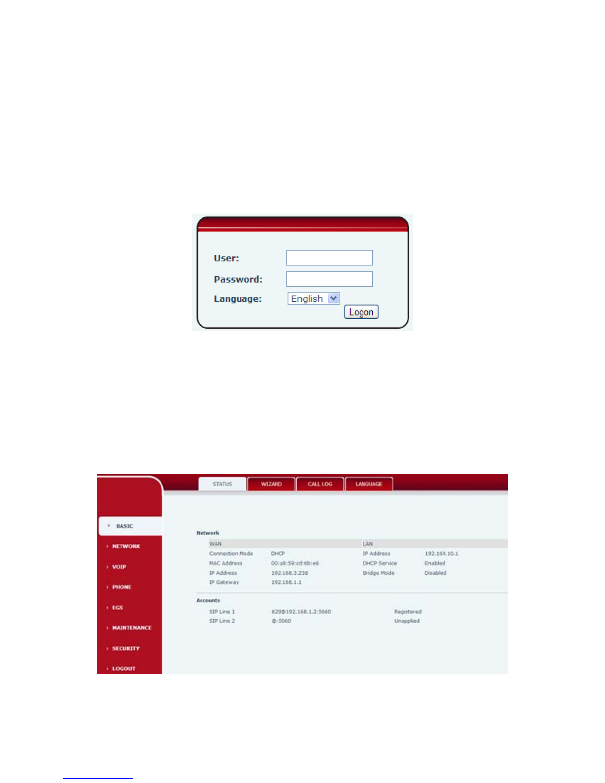
When I21/I21T and PC are connected to network,input phone IP address into Internet Explorer(IP address
can obtain via pressing sysinfo key)http://xxx
.xxx.xxx.xxx/,(if the web log on port is not 80 standard port,then need input http:
//xxx.xxx.xxx.xxx:xxxx/,otherwise it will show can not find a server
)You can see the web management interface login screen(as below image)。Enter the user name and password
and click on the【Logon】button then can enter into the set menu.
※:If you do not save the settings you changed,next power boot it will back to the previous state unchanged. If
you want to save the settings,after you made the change,please click Maintenance-Config-save then all are
saved,in the process, the phone will immediate effect without reboot.
4.3. WEB Page Functional Explanation
4.3.1. BASIC
4.3.1.1. Status
 Loading...