

Fanvil i20T User Manual
[䬂ܹ᭛ᄫ]
i20T
IP Voice Access User Manual

[䬂ܹ᭛ᄫ]
Safety Notices
1. Please use the specified power adapter. If special circumstances need to use the power adapter
provided by other manufacturers, please make sure the voltage and current provided in accordance
with the requirements of this product, meanwhile, please use the safety certificated products,
otherwise may cause fire or get an electric shock.
2. When using this product, please do not damage the power cord, or forcefully twist itǃStretch pull or
banding, and not to be under heavy pressure or between items, Otherwise may cause the power cord
damage, thus lead to fire or get an electric shock.
3. Before use, please confirm the temperature and environment humidity suitable for the product work.
(Move the product from air conditioning room to natural temperature, which may cause this product
surface or internal components produce condense water vapor, please open power use it after waiting
for this product is natural drying).
4. Non-technical staff not remove or repair, improper repair or may cause electric shock, fire or
malfunction, etcˈWhich can lead to injury accident, and also can cause your product damage.
5. Do not use fingers, pins, wire and other metal objects, foreign body into the vents and gaps. It may
cause current through the metal or foreign body, which even cause electric shock and injury accident.
If any foreign body or objection falls into the product please stop usage.
6. Please do not discard the packing bags or stored in places where children could reach, if children
trap his head with it, may cause nose and mouth blocked, and even lead to suffocation.
7. Please use this product with normal usage and operating, in bad posture for a long time to use this
product may affect your health.
8. Please read the above safety notices before installing or using this phone. They are crucial for the safe
and reliable operation of the device.

[䬂ܹ᭛ᄫ]
Directory
A. PRODUCT INTRODUCTION ............................................................................................................ 5
1. APPEARANCE OF THE PRODUCT .............................................................................................................. 5
2. BUTTON DESCRIPTION ......................................................................................................................... 5
B. START USING .................................................................................................................................... 6
1. CONNECTING THE POWER SUPPLY AND THE NETWORK .................................................................................. 6
1) Connecting network .................................................................................................................. 6
2) Connecting power supply........................................................................................................... 7
3) Electric Lock Connection Driver Option ...................................................................................... 7
4) Wiring instructions .................................................................................................................... 7
2. QUICK SETTING ................................................................................................................................. 9
C. BASIC OPERATION ............................................................................................................................ 9
1. ANSWER A CALL ................................................................................................................................ 9
2. CALL .............................................................................................................................................. 9
3. END CALL ....................................................................................................................................... 10
4. CALL RECORD .................................................................................................................................. 10
5. OPEN THE DOOR OPERATION ............................................................................................................... 10
D. PAGE SETTINGS ........................................................................................................................... 11
1. BROWSER CONFIGURATION ................................................................................................................ 11
2. PASSWORD CONFIGURATION .............................................................................................................. 11
3. CONFIGURATION VIA WEB ................................................................................................................. 12
(1) BASIC ................................................................................................................................... 12
a) STATUS ................................................................................................................................. 12
b) WIZARD ............................................................................................................................... 13
c) CALL LOG .............................................................................................................................. 15
(2) NETWORK ............................................................................................................................ 16
a) WAN .................................................................................................................................... 16
b) QoS&VLAN ........................................................................................................................... 18
c) SERVICE PORT ...................................................................................................................... 20
d) TIME&DATE .......................................................................................................................... 22
(3) VOIP ..................................................................................................................................... 23
a) SIP ....................................................................................................................................... 23
b) STUN .................................................................................................................................... 28
c) DIAL PEER ............................................................................................................................. 29
(4) PHONE ................................................................................................................................. 33

[䬂ܹ᭛ᄫ]
a) AUDIO .................................................................................................................................. 33
b) FEATURE .............................................................................................................................. 34
d) MCAST ................................................................................................................................. 37
(5) DOOR PHONE ....................................................................................................................... 40
a) FUNCTION KEY ..................................................................................................................... 40
b) DOOR PHONE ....................................................................................................................... 42
c) DOOR CARD ......................................................................................................................... 46
d) DOOR LOG ........................................................................................................................... 48
(6) MAINTENANCE ..................................................................................................................... 49
a) AUTO PROVISION ................................................................................................................. 49
b) SYSLOG ................................................................................................................................ 51
c) CONFIG ................................................................................................................................ 52
d) UPADTE ................................................................................................................................ 53
e) ACCESS ................................................................................................................................. 54
f) REBOOT ............................................................................................................................... 55
(7) SECURITY ............................................................................................................................. 55
a) WEB FILTER .......................................................................................................................... 55
b) FIREWALL ............................................................................................................................. 56
c) VPN ...................................................................................................................................... 57
d) SECURITY ............................................................................................................................. 59
(8) LOGOUT ............................................................................................................................... 60
E. APPENDIX ...................................................................................................................................... 61
1. TECHNICAL PARAMETERS .................................................................................................................... 61
2. BASIC FUNCTIONS ............................................................................................................................ 62
3. SCHEMATIC DIAGRAM ....................................................................................................................... 62
F. OTHER INSTRUCTIONS .................................................................................................................... 63
1. OPEN THE DOOR MODE ..................................................................................................................... 63
2. MANAGEMENT OF CARD .................................................................................................................... 64
[䬂ܹ᭛ᄫ]
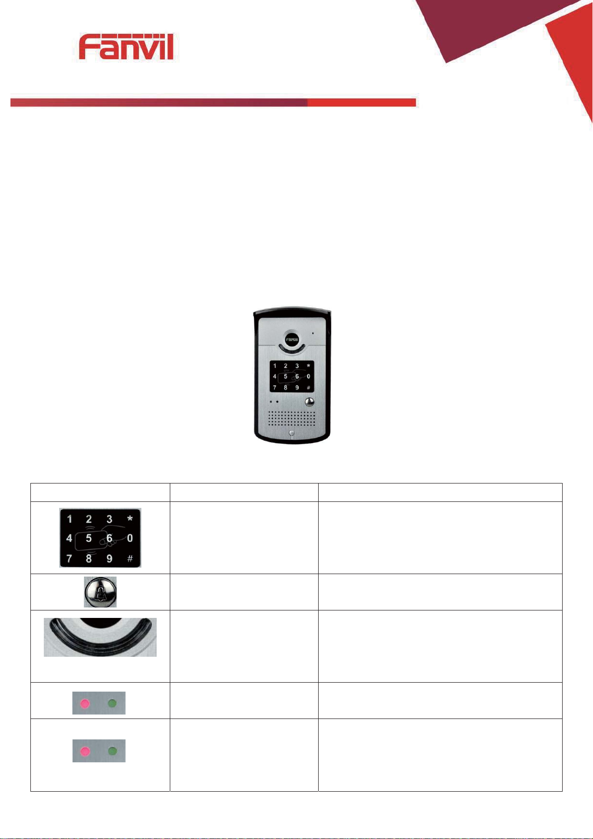
Buttom
Description
Function
digit keyboard
enter the password to open the door or make a
calling
Programmab
Can be set to a variety of functions, to meet the
needs of different occasions
call status
standby-light off
ring
hold/be hold
communication by telephone
power led
Long bright after
Network and SIP
status indicator
light
network failure 1 sec. glitter
network normal light off
registration failure 3 sec. glitter
registration succeed long bright
A. Product introduction
Voice Intercom i20T voice entrance guard is a full digital network door phoneˈits core part adopt
mature VoIP solution(Broadcom1190 chipset), stable and reliable performance, Hands-free adopting
digital full-duplex mode, Voice loud and clear, generous appearance, solid durable, easy for
installation, comfortable keypad, low power consumption.
i20T voice entrance guard support entrance guard control, Voice Intercom, ID card and keypad
remote to open the door.
1. Appearance of the product
2. Button description
le keyboard
indicators
(left)
-2 sec.glitter
-1sec. Glitter
-long bright
power supply
(right)
[䬂ܹ᭛ᄫ]
B. Start Using
Before you start to use equipment, please make the following installation:
1. Connecting the power supply and the network
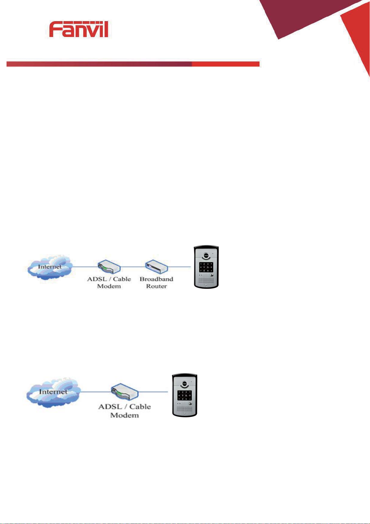
1) Connecting network
In prior to this step, please check if your network can work normally and have capacity of broadband
internet access.
z Broadband Router
Connect one end of the network cable to the intercom WAN port, the other end is connected to
your broadband router’s LAN port, so that the completion of the network hardware connections. In
most cases, you must configure your network settings to DHCP mode. Please refer to the detailed
setting ways: D, 3, (2), a) WAN.
z No Broadband Router
Connect one end of the network cable to the intercom WAN port, the other end is connected to
the broadband modem to your LAN port, so that the completion of the network hardware
connections. In most cases, if you are using the cable broadband, you must configure your network
settings to DHCP mode; if you are using the ADSL, you must configure your network settings to PPPoE
mode. Please refer to the detailed setting ways: D, 3, (2), a) WAN.

[䬂ܹ᭛ᄫ]
CN7
1 2 3 4 5 6 7
+12V
-12V
NC
COM
NO
S_I
S_O
12V 1A/DC
Electric Lock
Indoor switch
Jumper in passive mode
JP1 JP1
Jumper in active mode
2) Connecting power supply
i20T voice access can use 12V/DC power supply or an external power supply in POE mode. When
using POE mode, please make sure the network support POE, access network power supply can be
achieved.
3) Electric Lock Connection Driver Option
[Notice]When electric current of the electric lock is lower than 500mA/12V, it uses the internal driven
mode, by the POE or 12V DC to control the electric lock; When the electric current of the ele ctric lock is
higher than 500mA/12V, it uses the ex ternal driven mode, use specialized DC power to control the electric
lock.
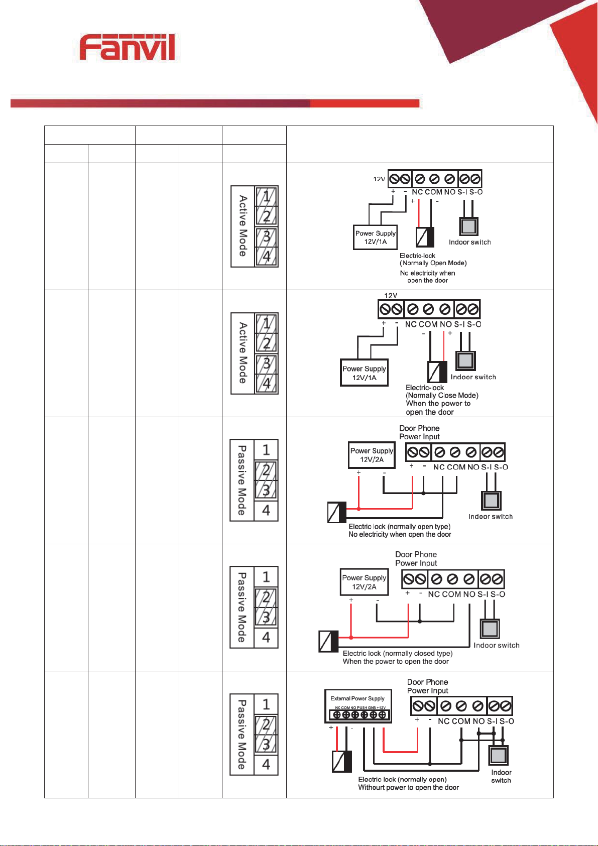
4) Wiring instructions
Relay connection description
z NO: Under the idle state is disconnected (normally open);
z COM: Contactor of the Relay (middle);
z NC: Under the idle state is connected (normally close).
[䬂ܹ᭛ᄫ]
Driving Mode
Electric lock
Jumper
Active
Passive
NO
NC
JP1
√ √
Connections
√ √
√ √
√ √
√ √

[䬂ܹ᭛ᄫ]
2. Quick Setting
The product Provide a complete function and parameter setting, users may need to have the network
and SIP protocol knowledge for understanding the meaning represented by all parameters. In order to let
equipment users can quickly enjoy the high quality speech brought by the IP Phone services and low cost
advantage, we especially lists the basic and must set options in this section, which let users can real-time
started without understanding complex SIP protocols.
In prior to this step, please make sure your broadband Internet online can be normal operation, and
complete the connection of the network hardware. The product factory default network mode is DHCP.
Thus, only connect equipment with DHCP network environment then network can be automatically
connected.
¾ A long press # key 3 seconds, automatic voice playing device's IP address, or use the
"iDoorPhoneNetworkScanner.exe " software to find the IP address of the device;
¾ Log on to the WEB device configuration;
¾ In a SIP page configuration service account, user name, parameters that are required for server
address register;
¾ You can settings DSS key in the Webpage(functions key settings -> function key);
¾ You can settings function parameters in the Webpage (Intercom-> feature);
C. Basic operation
1. Answer a call
When calling come, the device automatically answer, in cancel automatic answer and settings
automatic answer time, will hear the bell in the set time, automatic answer after a timeout.
2. Call
Configuration shortcut as hot key and setup a number, then press shortcut can call the configured
number immediately.

[䬂ܹ᭛ᄫ]
3. End call
Enable Release key hang up to end call.
4. Call record
The device provides 300 call recording, when the storage space is exhausted, will cover the first call
records. When the device is powered down or reboot, call records will be removed.
You can view the three call records in the Webpage (Basic->call log)
5. Open the door operation
Through the following four ways to open the door:
1) Local open the door on the keyboard input password to open the door.
2) Access to call the owner; enter the remote to open the door by the owner password to open the
door.
3) Owner/call access control of other equipment and enter the access code and press # key to open the
door (access code to be included in the list to access configuration).
4) Through the RFID CARDS to open the door.
Access code input correct prompt sowing sirens prompt access control and the remote user, input error
by short low frequency chirp.
Password successfully by high-frequency sirens sound prompt, input error is short by high frequency
chirp.
When the door opened by playing sirens sound prompt.
[䬂ܹ᭛ᄫ]
D. Page settings
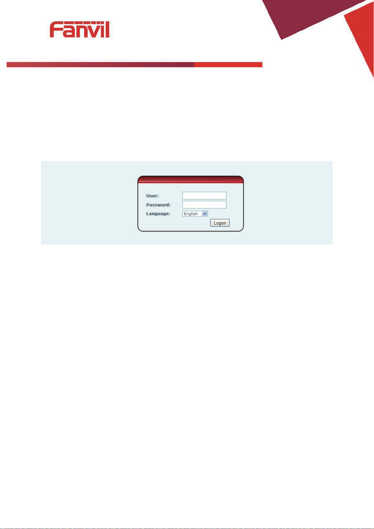
1. Browser configuration
When the device and your computer successfully connected to the network, the on browsers
enter the IP address of the device. You can see the Webpage management interface the login screen.
Enter the user name and password and click [logon] button to enter the settings screen.
After configuring the equipment, remember to click SAVE under the Maintenance tab. If this is
not done, the equipment will lose the modifications when it is rebooted.
2. Password Configuration
There are two levels of access: root level and general level. A user with root level access can
browse and set all configuration parameters, while a user with general level can set all configuration
parameters except server parameters for SIP.
z Default user with general level:
Username: guest
Password: guest
z Default user with root level:
Username: admin
Password: admin

[䬂ܹ᭛ᄫ]
Status
Field Name
Explanation
Network
Shows the configuration information for WAN and LAN port, including connection mode
of WAN port (Static, DHCP, PPPoE),MAC
Accounts
Shows the phone numbers and registration status for the 2 SIP LINES and 1 IAX2 server.
3. Configuration via WEB
(1) BASIC
a) STATUS
address, IP address of WAN port.
[䬂ܹ᭛ᄫ]
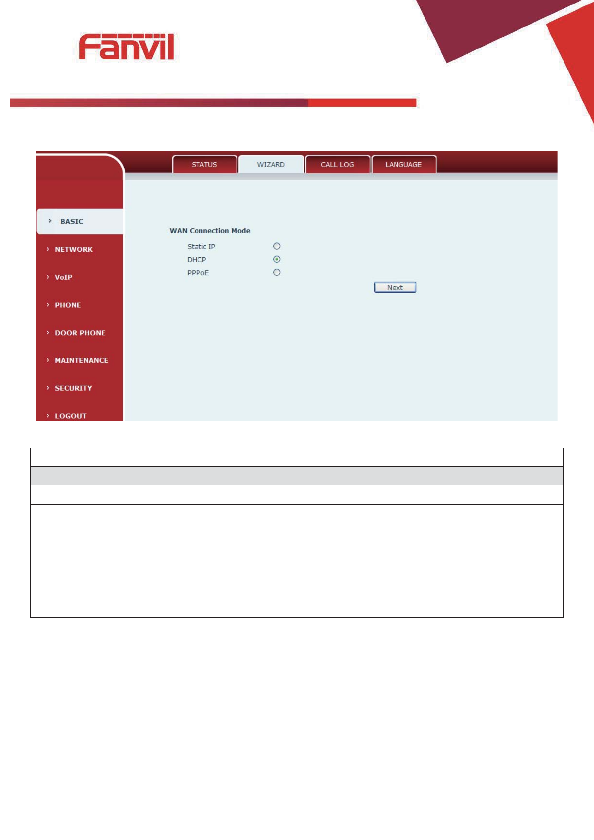
Wizard
Field Name
Explanation
Select the appropriate network mode. The equipment supports three network
Static IP mode
The parameters of a Static IP connection must be provided by your ISP.
DHCP mode˖
In this mode, network parameter information will be obtained automatically from a
DHCP server.
PPPoE mode˖
In this mode, you must enter your ADSL account and password.
Static IP mode is selected; Click Next to go to Quick SIP Settings, Click Back to return to the Wizard
screen.
b) WIZARD
modes:
[䬂ܹ᭛ᄫ]
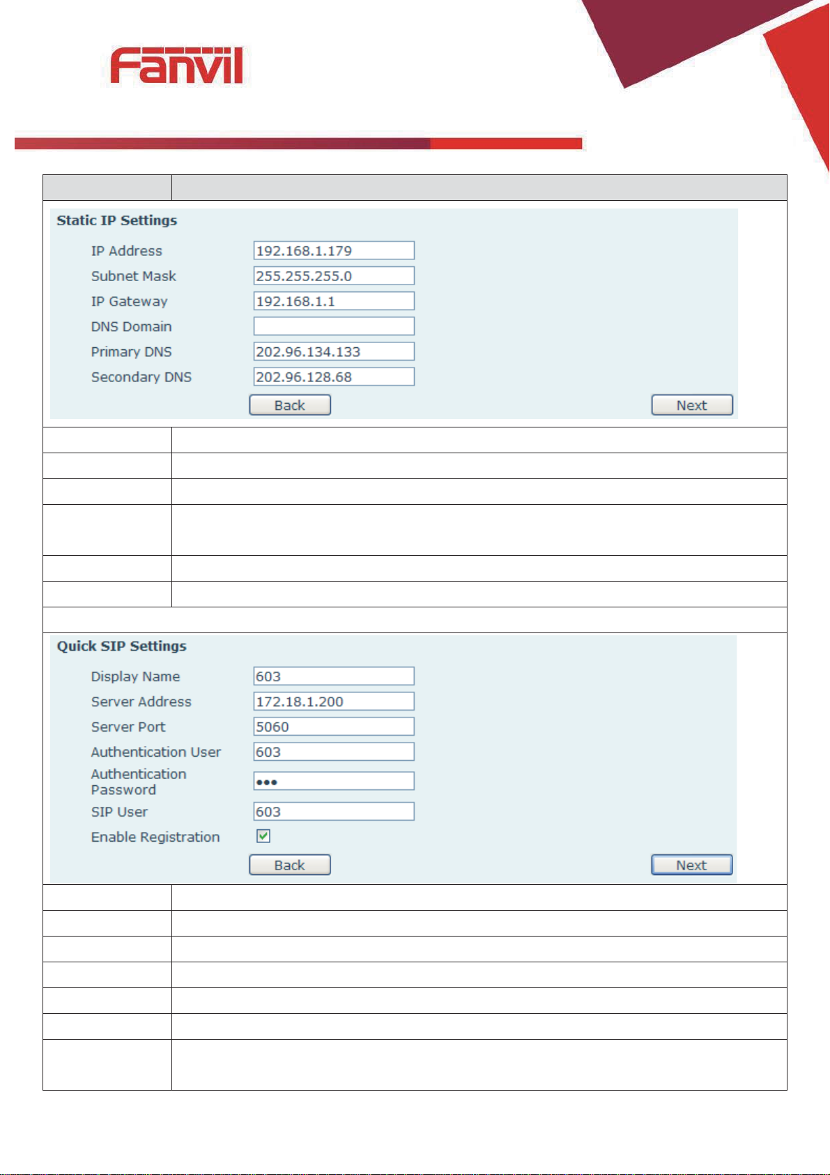
Field Name
Explanation
Static IP address
Please enter the Static IP address
Subnet Mask
Please enter the Subnet Mask
IP Gateway
Please enter the IP Gateway
DNS Domain
Set the DNS domain suffix. When the user enter the domain name DNS address cannot
be resolved, the domain equipment to resolve in the domain name.
Primary DNS
Please enter the Primary DNS server address
Secondary DNS
Please enter the Secondary DNS server address
Quick SIP Settings
Display Name
The name shown in caller ID
Server Address
SIP server address either IP address or URI
Server Port
SIP server port (usually 5060)
User
Login name or Authentication IDDŽ
Password
SIP password
SIP User
Phone number
Enable
Registration
Submits registr
ation information. Normally checked
[䬂ܹ᭛ᄫ]
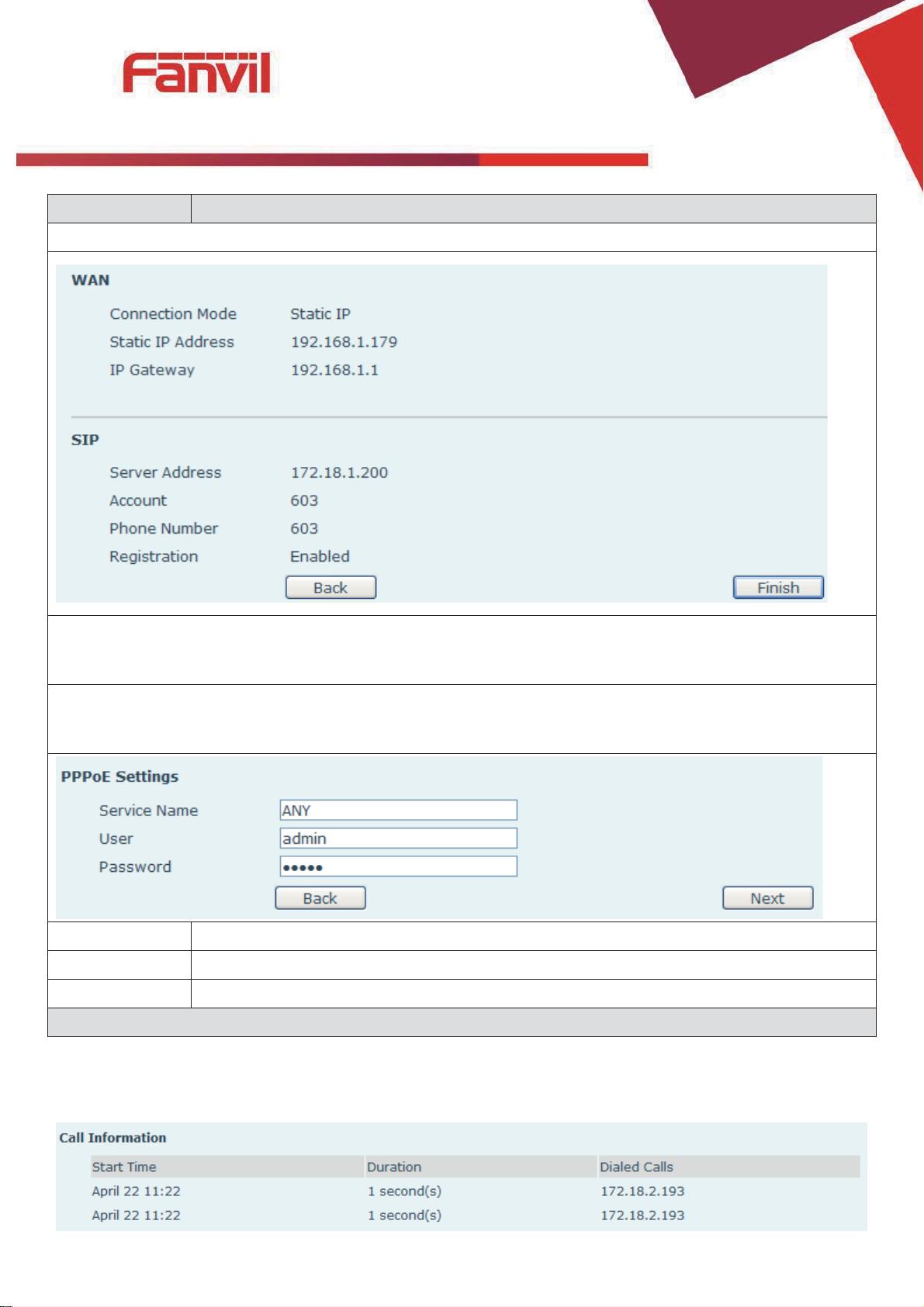
Field Name
Explanation
Displays detailed information for manual configuration.
After selecting DHCP and clicking NEXT, the Quick SIP Settings screen will appear. Click Back to return to
the Wizard screen. Click Ne
If PPPoE is selected, this screen will appear. Enter the information provided by the ISP. Click Next to go
to Quick SIP Setting. Click Back to return to the Wizard screen.
Service Name
PPPoE Service name, Usually the default value.
User
ADSL user account
Password
ADSL password
Click Finish button to save settings and reboot. After the reboot, SIP calls can be made.
xt to go to the Summary screen.
c) CALL LOG
Outgoing call logs can be seen on this page
[䬂ܹ᭛ᄫ]
Call log
Field Name
Explanation
Start time
Start time of the outgoing call
Duration
Duration of the outgoing call
Dialed calls
Account, protocol, and line of the outgoing call
Call type
Placed, Missed, Received
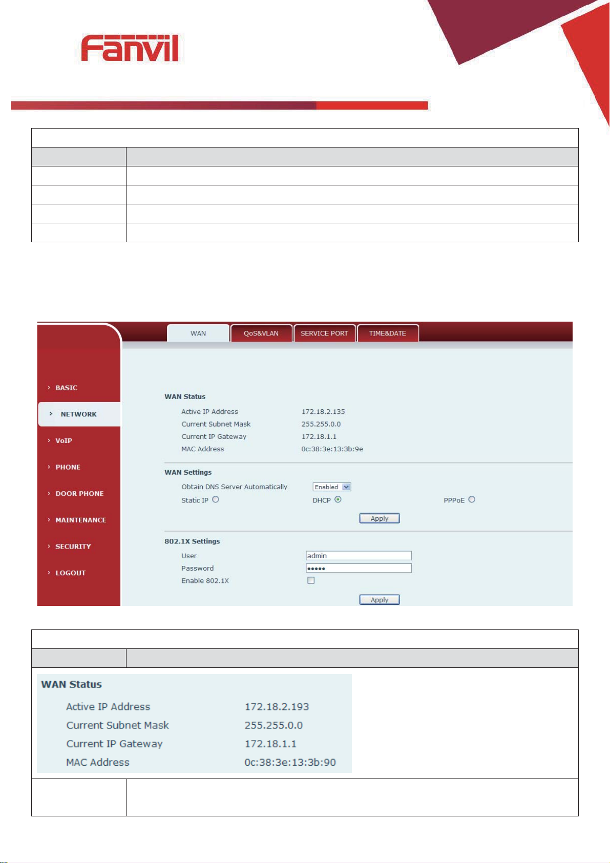
WAN
Field Name
Explanation
Active IP
address
The current IP addre
(2) NETWORK
a) WAN
ss of the equipment

[䬂ܹ᭛ᄫ]
Field Name
Explanation
Current subnet
mask
The current Subnet Mask
Current IP
gateway
The current Gateway IP address
MAC address
The MAC address of the equipment
Select the appropriate network mode. The equipment supports three network modes:
Static
Network parameters must be entered manually and will not change. All parameters are
provided by the ISP.
DHCP
Network parameters are provided automatically by a DHCP server.
PPPoE
Account and Password must be input manually. These are provided by your ISP.
If Static IP is chosen, the screen below will appear. Enter values provided by the ISP.
Static IP address
Please enter the Static IP address
Subnet mask
Please enter the Subnet Mask
Gateway
Please enter the IP Gateway
DNS
Set the DNS domain suffix. When the user enter the domain name DNS address cannot
be resolved, the domain equipment to resolve in the domain name.
Primary DNS
Please enter the Primary DNS server address
Secondary DNS
Please enter the Secondary DNS server address
Domain
[䬂ܹ᭛ᄫ]
Field Name
Explanation
802.1X Settings
User
802.1X user account
Password
802.1X password
Enable 812.1X
Open/Close 812.1X
After entering the new settings, click the APPLY button. The equipment will save the new settings and
, it must be used to login to the phone
apply them. If a new IP address was entered for the equipment
after clicking the APPLY button.
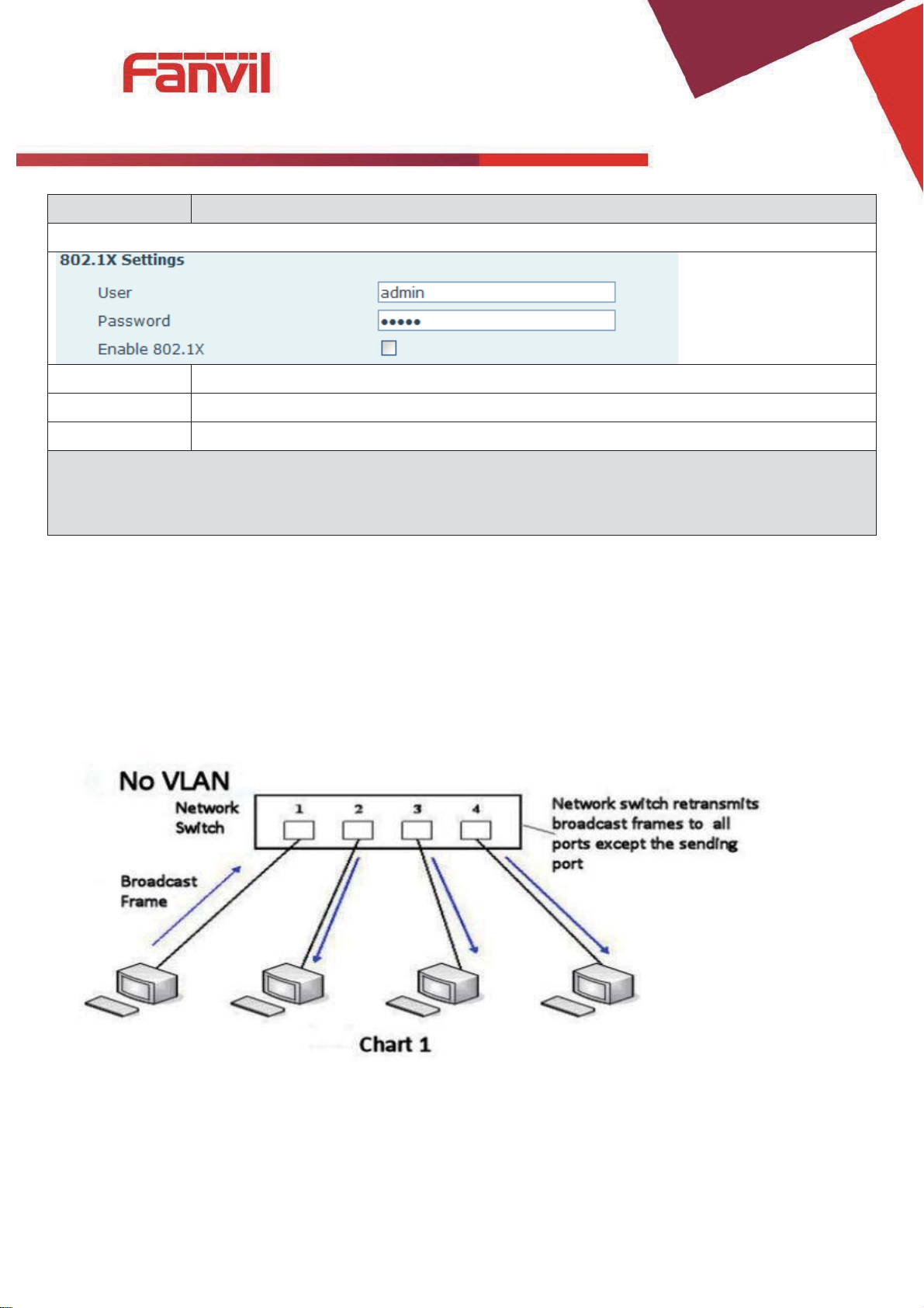
b) QoS&VLAN
The equipment supports 802.1Q/P protocol and DiffServ configuration. Use of a Virtual LAN (VLAN)
allows voice and data traffic to be separated.
¾ Chart 1 shows a network switch with no VLAN. Any broadcast frames will be transmitted to all other
ports. For example, and frames broadcast from Port 1 will be sent to Ports 2, 3, and 4.
[䬂ܹ᭛ᄫ]
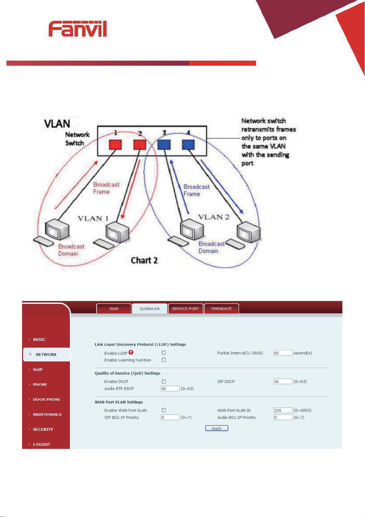
¾ Chart 2 shows an example with two VLANs indicated by red and blue. In this example, frames
broadcast from Port 1 will only go to Port 2 since Ports 3 and 4 are in a different VLAN. VLANs can be
used to divide a network by restricting the transmission of broadcast frames.
Note: In practice, VLANs are distinguished by the use of VLAN IDs.

[䬂ܹ᭛ᄫ]
QoS&VLAN
Field Name
Explanation
LLDP Settings
Enable LLDP
Enable or Disable Link Layer Discovery Protocol (LLDP)
Enable Learning
Function
Enables the telephone to synchronize its VLAN data with the Network Switch. The
telephone will automatically synchronize DSCP, 802.1p, and VLAN ID values even if
these values differ from those provided by the LLDP server.
Packet Interval
The time interval for sending LLDP Packets
QOS Settings
Enable DSCP
Enable or Disable Differentiated Services Code Point (DSCP)
Audio RTP DSCP
Specify the value of the Audio DSCP in decimal
SIP DSCP
Specify the value of the SIP DSCP in decimal
WAN Port VLAN Settings
Enable WAN Port
VLAN
Enable or Disable WAN Port VLA
WAN Port VLAN ID
Specify the value of the WAN Port VLAN ID. Range is 0-4095
SIP 802.1P Priority
Specify the value of the signal 8021.p priority. Range is 0-7
Audio 802.1P Priority
Specify the value of the voice 802.1p priority. Range is 0-7
c) SERVICE PORT
Set the port values for Telnet/HTTP/RTP on this page.
N

[䬂ܹ᭛ᄫ]
Service port
Field Name
Explanation
Web Server type
Specify Web Server Type – HTTP or HTTPS
HTTP port
Port for web browser access. Default value is 80. To enhance security, change this from
t
Example: The IP address is 192.168.1.70 and the port value is 8090, the accessing
address is http://192.168.1.70:8090.
HTTPS port
Port for HTTPS access. Before using https, an https authentication certification must be
downloaded into the equipment.
Default value is 443. To enhance security, change this from the default.
Telnet port
Port for Telnet access. The default is 23.
RTP port range
start
Set the beginning value for RTP Ports. Ports are
RTP port
quantity
Set the maximum quantity of RTP Ports. The default is 200.
Note:
1) Any changes made on this page require a reboot to become active.
2) It is suggested that changes to HTTP Port and Telnet ports be values greater than 1024.Values less than
1024 are reserved.
3) If the HTTP port is set to 0, HTTP service will be disabled.
he default. Setting this port to 0 will disable HTTP access.
dynamically allocated.
 Loading...