

Fanvil i10, i10V, i10D User Manual
˖
User Manual
Software Version: 1.0.0
Release Date
2019/07/24
i10&i10V&i10D

ˍ
ˏ
ˑ
Directory
Directory ......................................................................................................................................... ˍˍ
1 Picture ...................................................................................................................................
2 Table ......................................................................................................................................
3 Safety Instruction .................................................................................................................. 1
4 Overview ................................................................................................................................. 2
5 Install Guide ........................................................................................................................... 3
5.1 Use POE or external Power Adapter ............................................................................. 3
5.2 Appendix Table ............................................................................................................... 4
5.2.1 Common command mode.................................................................................... 4
5.2.2 Function key LED state ........................................................................................ 4
6 Basic Introduction ................................................................................................................. 5
6.1 Panel Overview .............................................................................................................. 5
6.2 Quick Setting .................................................................................................................. 5
6.3 WEB configuration .......................................................................................................... 6
6.4 SIP Configurations ......................................................................................................... 7
7 Basic Function ................................................................................................................ ....... 8
7.1 Making Calls ................................................................................................................... 8
7.2 Answering Calls .............................................................................................................. 8
7.3 End of the Call ................................................................................................................ 8
7.4 Auto-Answering .............................................................................................................. 8
7.5 Call Waiting .................................................................................................................. 10
8 Advance Function ................................................................................................................ 11
8.1 Intercom ........................................................................................................................ 11
8.2 MCAST ......................................................................................................................... 11
8.3 Hotspot ......................................................................................................................... 13
9 Web Configurations ............................................................................................................. 15
9.1 Web Page Authentication ............................................................................................. 15
9.2 System >> Information ................................................................................................. 15
9.3 System >> Account ...................................................................................................... 16
9.4 System >> Configurations ............................................................................................ 16
9.5 System >> Upgrade ..................................................................................................... 17
9.6 System >> Auto Provision ............................................................................................ 19
9.7 System >> FDMS ......................................................................................................... 22
9.8 System >> Tools........................................................................................................... 22

ˎ
9.9 Network >> Basic ......................................................................................................... 23
9.10 Network >> Service Port .............................................................................................. 25
9.11 Network >> VPN ........................................................................................................... 26
9.12 Line >> SIP ................................................................................................................... 27
9.13 Line >> SIP Hotspot ..................................................................................................... 32
9.14 Line >> Basic Settings .................................................................................................. 32
9.15 Intercom Setting >> Features ....................................................................................... 34
9.16 Intercom Setting >> Audio ............................................................................................ 36
9.17 Intercom Setting >> MCAST ........................................................................................ 37
9.18 Intercom Setting >> Action ........................................................................................... 38
9.19 Intercom Setting >> Time/Date .................................................................................... 38
9.20 Intercom settings >> Tone............................................................................................ 39
9.21 Call List >> Call List ...................................................................................................... 40
9.22 Web Dial ....................................................................................................................... 41
9.23 Function Key ................................................................................................................. 41
9.24 Security >> Web Filter .................................................................................................. 45
9.25 Security >> Trusted Certificates ................................................................................... 45
9.26 Security >> Device Certificates .................................................................................... 46
9.27 Security >> Firewall ...................................................................................................... 47
9.28 Device Log .................................................................................................................... 48
9.29 Security Settings........................................................................................................... 48
10 Trouble Shooting ................................................................................................................. 52
10.1 Get device system information ..................................................................................... 52
10.2 Reboot device ............................................................................................................... 52
10.3 Device factory reset ...................................................................................................... 52
10.4 Network Packets Capture ............................................................................................. 52
10.5 Get Log Information ...................................................................................................... 53
10.6 Common Trouble Cases .............................................................................................. 53

ˏ
1 Picture
Figure 1 - Panel ....................................................................................................................... 5
Figure 2 - Quickly setting ......................................................................................................... 6
Figure 3 - WEB Login .............................................................................................................. 6
Figure 4 - SIP Line Configuration ............................................................................................ 7
Figure 5 - Function Setting ...................................................................................................... 8
Figure 6 - Enable Auto Answer ................................................................................................ 9
Figure 7 - Enable Auto Answer ................................................................................................ 9
Figure 8 - Call Waiting ........................................................................................................... 10
Figure 9 - Intercom ................................................................................................................ 11
Figure 10 - MCAST ................................................................................................................ 12
Figure 11 - SIP Hotspot ......................................................................................................... 14
Figure 12 - WEB Account ...................................................................................................... 16
Figure 13 - System Setting .................................................................................................... 16
Figure 14 - Upgrade .............................................................................................................. 17
Figure 15 - Online Upgrade ................................................................................................... 18
Figure 16 - Auto Provision ..................................................................................................... 19
Figure 17 - FDMS .................................................................................................................. 22
Figure 18 - Tools .................................................................................................................... 23
Figure 19 - Network Basic Settings ....................................................................................... 23
Figure 20 - Service Port ......................................................................................................... 25
Figure 21 - VPN ..................................................................................................................... 26
Figure 22 - SIP ....................................................................................................................... 28
Figure 23 - Network Basic ..................................................................................................... 33
Figure 24 - Line Basic Setting ............................................................................................... 33
Figure 25 - Intercom Setting .................................................................................................. 34
Figure 26 - Media Setting ...................................................................................................... 36
Figure 27 - MCAST ................................................................................................................ 37
Figure 28 - time/date ............................................................................................................. 38
Figure 29 - Tone ..................................................................................................................... 40
Figure 30 - Call List ............................................................................................................... 40
Figure 31 - Web Dial .............................................................................................................. 41
Figure 32 - Function Key ....................................................................................................... 42
Figure 33 - Function Key Settings ......................................................................................... 43
Figure 34 - Memory Key Settings .......................................................................................... 44
Figure 35 - Multicast Settings ................................................................................................ 44
Figure 36 - Multicast Settings ................................................................................................ 45

ː
Figure 37 - Trusted Certificates ............................................................................................. 46
Figure 38 - Device Certificates .............................................................................................. 46
Figure 39 - Firewall ................................................................................................................ 47
Figure 40 - Security Settings ................................................................................................. 49

ˑ
2 Table
Table 1 - Common command mode ........................................................................................ 4
Table 2 - Function key LED state ............................................................................................ 4
Table 3 - Panel introduction ..................................................................................................... 5
Table 4 - Intercom .................................................................................................................. 11
Table 5 - MCAST ................................................................................................................... 12
Table 6 - SIP Hotspot ............................................................................................................. 13
Table 7 - Online Upgrade....................................................................................................... 18
Table 8 - Auto Provision ......................................................................................................... 20
Table 9 - FDMS ...................................................................................................................... 22
Table 10 - Network Basic Setting .......................................................................................... 24
Table 11 - Service port ........................................................................................................... 25
Table 12 - Line Basic Setting ................................................................................................. 33
Table 13 - Intercom Setting ................................................................................................... 34
Table 14 - Media Setting ........................................................................................................ 36
Table 15 - action URL ............................................................................................................ 38
Table 16 - time/date ............................................................................................................... 38
Table 17 - Function Key ......................................................................................................... 42
Table 18 - Function Key Settings ........................................................................................... 43
Table 19 - Memory Key Settings ........................................................................................... 44
Table 20 - Multicast Settings ................................................................................................. 44
Table 21 - Firewall ................................................................................................................. 47
Table 22 - Security Settings ................................................................................................... 49
Table 23 - Common Trouble Cases ....................................................................................... 53

1
3 Safety Instruction
Please read the following safety notices before installing or using this unit. They are
crucial for the safe and reliable operation of the dev i ce.
z Please use the external power supply that is included in the package. Other power
supply may cause damage to the phone and affect the behavior or induce noise.
z Before using the external power supply in the package, please check the home
power voltage. Inaccurate power v oltage may cause fire and damage.
z Please do not damage the power cord. If the power cord or plug is impaired, do not
use it because it may cause fire or electric shock.
z Do not drop, knock or shake the phone. Rough handling can break internal circuit
boards.
z This phone is designed for indoor use. Do not install the device in places where
there is direct sunlight. Also do not put the device on carpets or cushions. It may
cause fire or breakdown.
z Avoid exposure the phone to high temperature or below 0ȭ or high humidity.
z Avoid wetting the unit with any liquid.
z Do not attempt to open it. Non-expert handling of the device could damage it.
Consult your authorized dealer for help, or else it may cause fire, e lectric shock an d
breakdown.
z Do not use harsh chemicals, cleaning solvents, or strong detergents to clean it.
Wipe it with a soft cloth that has been slightly dampened in a mild soap and water
solution.
z When lightning, do not touch the power plug, it may cause an electric shock.
z Do not install this phone in an ill-ventilated place. You are in a situation that could
cause bodily injury. Before you work on any equipment, be aware of the hazards
involved with electrical circuitry and be familiar with standard practices for
preventing accidents.

2
4 Overview
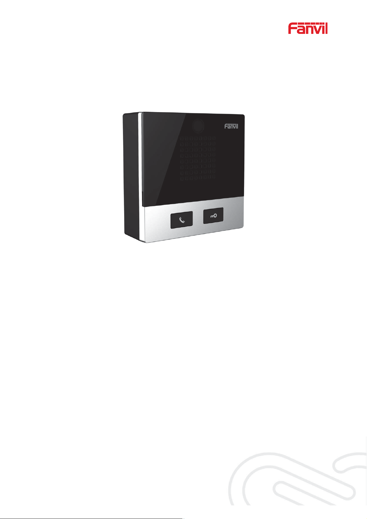
The i10/i10V/i10D SIP mini intercom is designed for indoor scenes with IP54 waterproof and
dustproof. Supports wall mounting installation. It combines security, audio/video intercom and
broadcasting functionalities and offers a qualified communication solution for users.

3
5 Install Guide
5.1 Use POE or external Power Adapter
i10/i10V/i10D, called as ‘the device’ hereafter, supports two power supply modes, power supply
from an external power adapter or over Ethernet (POE) complied switch.
POE power supply saves the space and cost o f providing the device an additional power outlet.
With a POE switch, the device can be powered through a single Ethernet cable which is also
used for data transmission. By attaching UPS system to POE switch, the device can keep
working at power outage just li ke traditional PS TN telephone w hich is p owered by the telepho ne
line.
For users who do not have POE equip ment, the tra ditiona l pow er adaptor sh o uld be u sed. If the
device is connected to a POE switch and power adapter at the same time, the power adapter
will be used in priorit y and will switch to POE power supply once it fails.
Please use the power adapter supplied by Fanvil and the POE switch met the specifications to
ensure the device works properly.

4
Action
Description
IP Broadcast under
standby mode
In standby mode, long press the speed dial button for 3 seconds,
there will be a toot sound will 5 seconds, please press the speed
dial button once within 5 seconds, the toot soun
ill stop
automatically reporting IP
Switch network
mode
In the standby mode, long-press the speed dial button for 3
seconds and the beep will last for 5 seconds. Within 5 seconds,
press the speed dial button three times quickly to switch to the
network
If there is no IP at present, switch to the default static IP
(192.168.1.128).
Then switch to DHCP mode when it is the default static IP
(192.168.1.128)
When DHCP gets to IP, then do not switch and report the IP
directly.
Report the IP after the successful switch.
Type
LED
State
Speed dial
Normally on
Successfully registered
Quick flashing
Registration failed/ network abnormal
Slow flashing
In call
5.2 Appendix Table
5.2.1 Common command mode
Table 1 - Common co mmand mode
mode.
d w
5.2.2 Function key LED state
Table 2 - Function key LED state
5
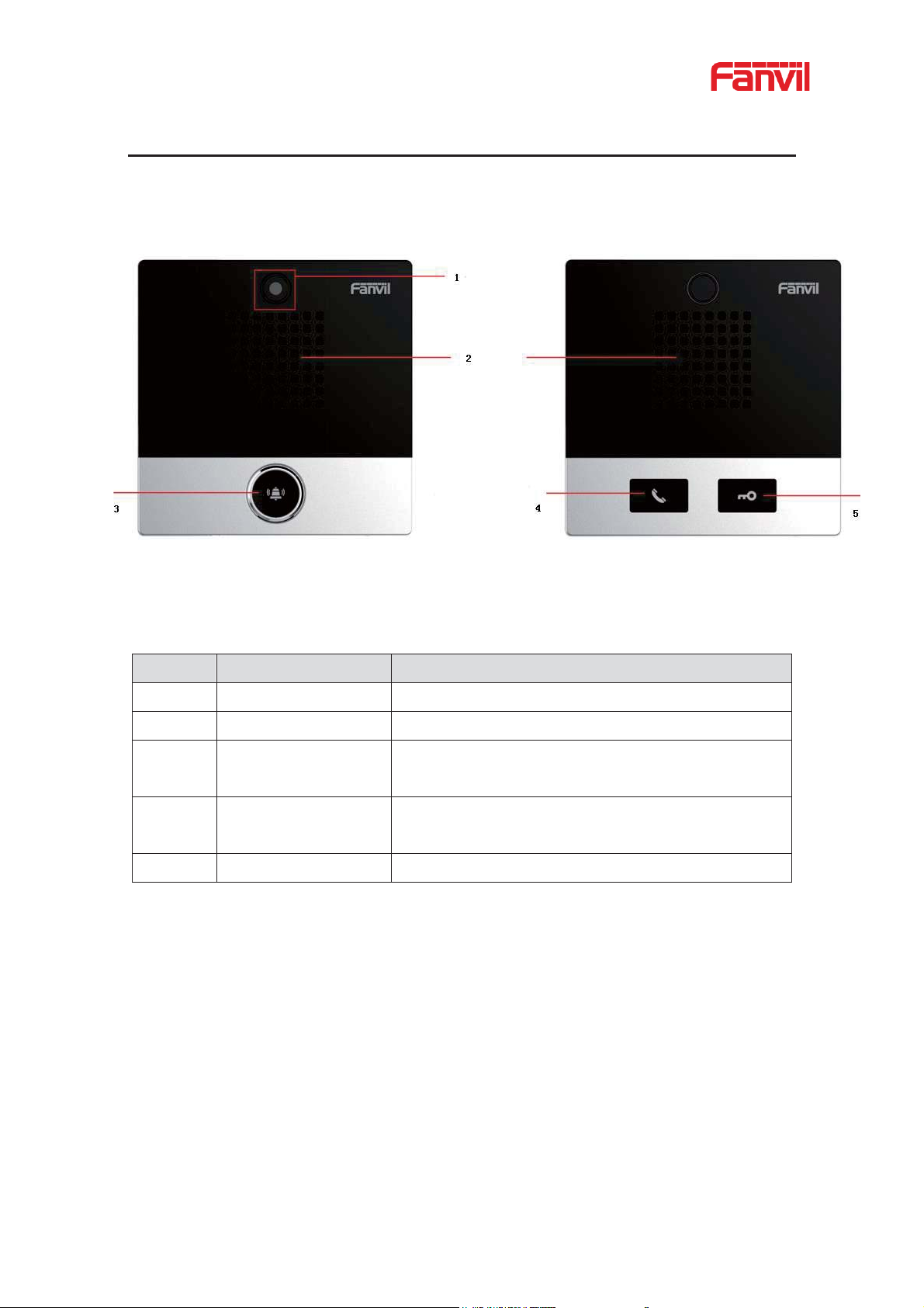
Number
Name
Description
1
IP Camera
Video signal acquisition a nd transmission
2
Speaker
Play sound
3
Speed dial button
For speed dial, multicast, intercom, IP broadcast and
other functions
4
Speed dial/Answer
button
For speed dial/answer button, multicast, intercom, IP
broadcast and other functions
5
Unlock
Unlock door
6 Basic Introduction
6.1 Panel Overview
Figure 1 - Panel
Table 3 - Panel introduct i on
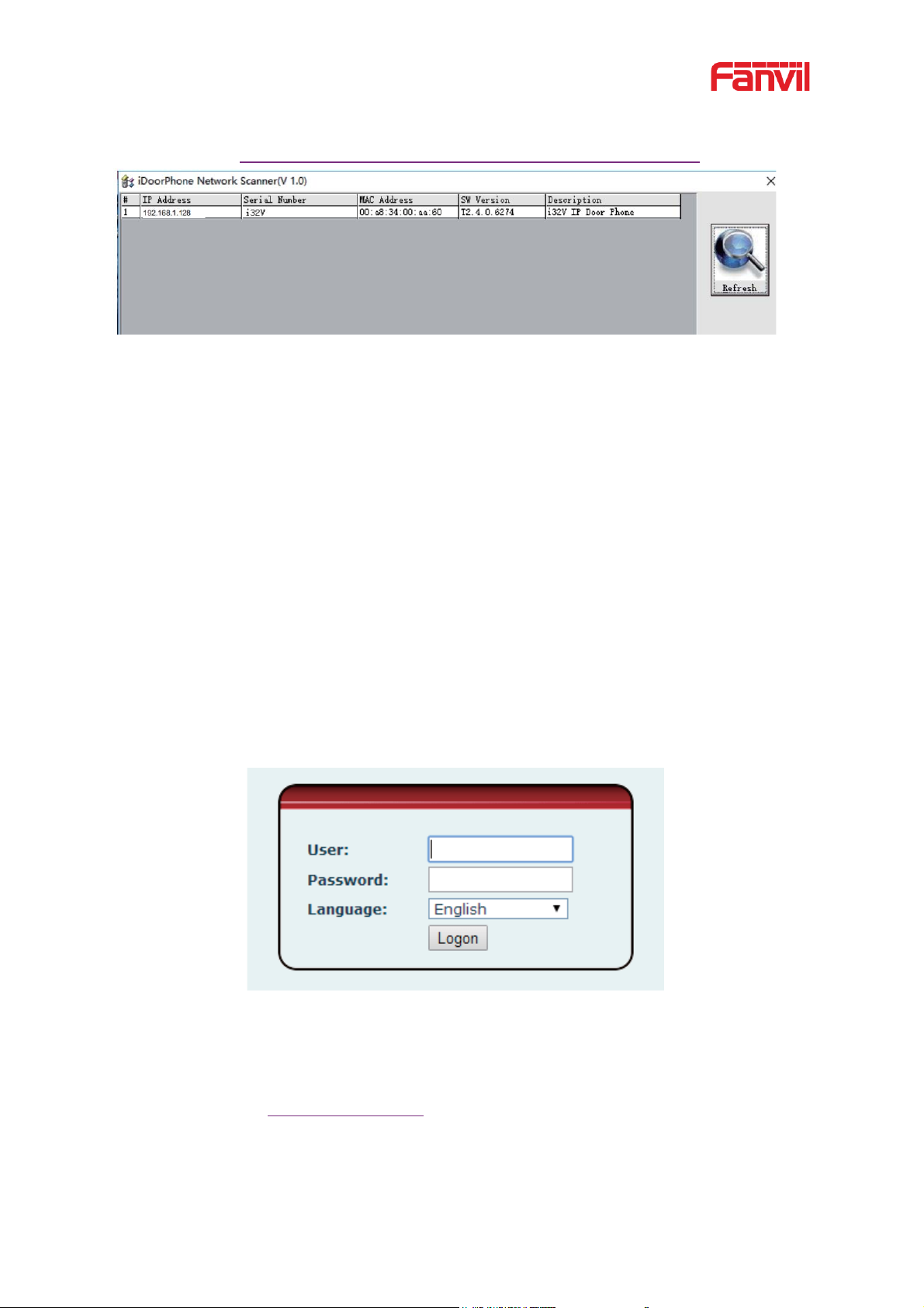
6.2 Quick Setting
Before proceeding with this step, make sure your Internet broadband connection is working
properly and complete the network hardware con nection. The default factory mode is DHCP. IP
address can be viewed by.
In standby mode, long press the speed dial button for 3 seconds, there will be a toot sound
will 5 seconds, please pre ss the speed dial button once within 5 seconds (please do not
operate within 30 seconds when power on), the toot sound will stop auto m atically reporting
IP.
Of the device or use the "IP scann ing too l. exe"
6
software to find the IP address of the device.
˄Download http://download.fanvil.com/tool/iDoorPhoneNetworkScanner.exe˅
Figure 2 - Quickly setting
In the standby mode, long-press the speed dial button for 3 seconds and the beep will last
for 5 seconds. Within 5 seconds, press the speed dial button three times quickly to switch
to the network mode.
Login to the device's WEB page for con f iguration according to the IP address
Configure the account, user name, server addres s and other parameters required for
registration provided by the service provider on the WEB configuration page;
6.3 WEB configuration
When the device and your computer are successfully connected to the network, enter the IP
address of the device on the browser as http://xxx.xxx.xxx.xxx/ and you can see the login
interface of the web page manage me nt.
Figure 3 - WEB Login
The username and password should be correct to log in to the web page. The default
username and password are "admin". For the specific details of the operation of the web
page, please refer to 9 Web Configurations
7
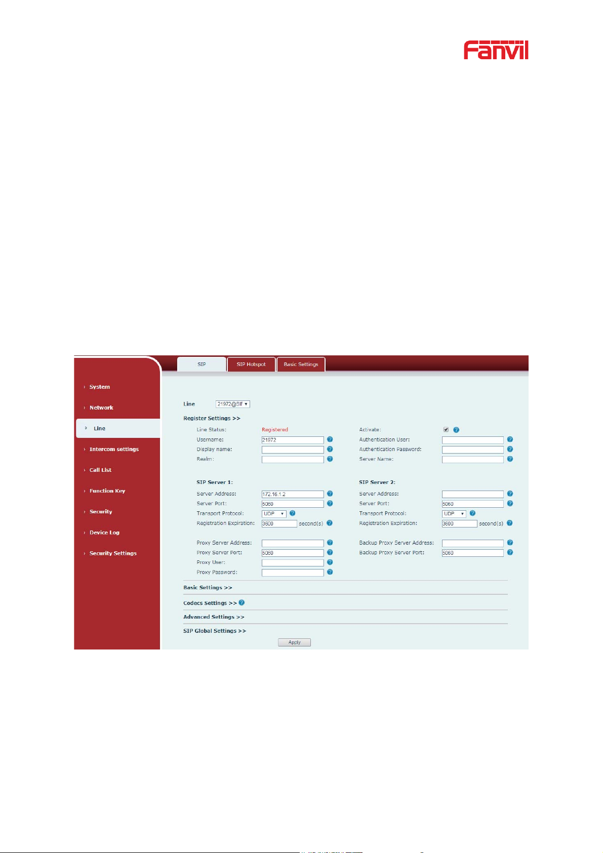
6.4 SIP Configurations
At least one SIP line should be configured properly to enable the telephony service. The line
configuration is like a virtualized SIM card. Just like a SIM card on a mobile phone, it stores the
service provider and the account information used for registration and authentication. When the
device is applied with the configurat ion, it will r egist er t he device to t he serv ice provider wit h the
server’s address and user’s authentication is stored in the configur ations.
The SIP line configuration should be s et v ia the WEB configuration pag e by entering the corr ect
information such as phone number, authentication name/password, SIP server address, server
port, etc. which are provided by the SIP server administrator.
z WEB interface˖After login into the phone page, enter [Line] >> [SIP] and s elect SIP1/SIP2
for configuration, click apply to complete registration after config urat ion, as shown below:
Figure 4 - SIP Line Configuration
8
˖
7 Basic Function
7.1 Making Calls
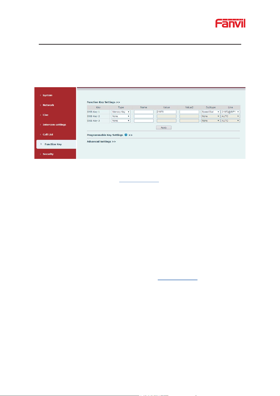
After setting the function key to memory key and the subtype as speed dial and setting the
number, press the function key to immediately call out the set number, as shown below:
Figure 5 - Function Setting
See detailed configuration instructions 9.23 Function Key
7.2 Answering Calls
After setting up the autom at ic answer and setting up the automatic answer time, it will hear the
ringing bell within the set time and automatically answ er the call after the timeout. Cancel
automatic answering. When a call comes in, you will hear the ringing bell and will not answer
the phone over time.
7.3 End of the Call
When there is a call, you can press the speed dia l button to hang u p the call, the default setting
is to end the call. See detail ed configuration instructions 9.23 Function Key.
7.4 Auto-Answering
The user can turn off the auto-answer function (enabled by default) on the device webp age, and
the ring tone will be heard after the shutdown, and the auto-a nswer w ill not time out.
z Enable auto answering on the line˖
Web interface: enter [Line] >> [SIP], Enable auto answer, set mode and auto answer time and
click submit.

9
Figure 6 - Enable Auto Answer
z Enable auto answering P2P:
Web interface: enter [line] >> [Basic Settings] >> [SIP P2P Settings], enable automatic
answering, setting mode and automatic an swering time, and click submit.
Figure 7 - Enable Auto Answer
z Auto Answer Timeout炷0~60炸
The range can be set to 0~60s, and the call will be answered automatically when the timeout is
set.
10
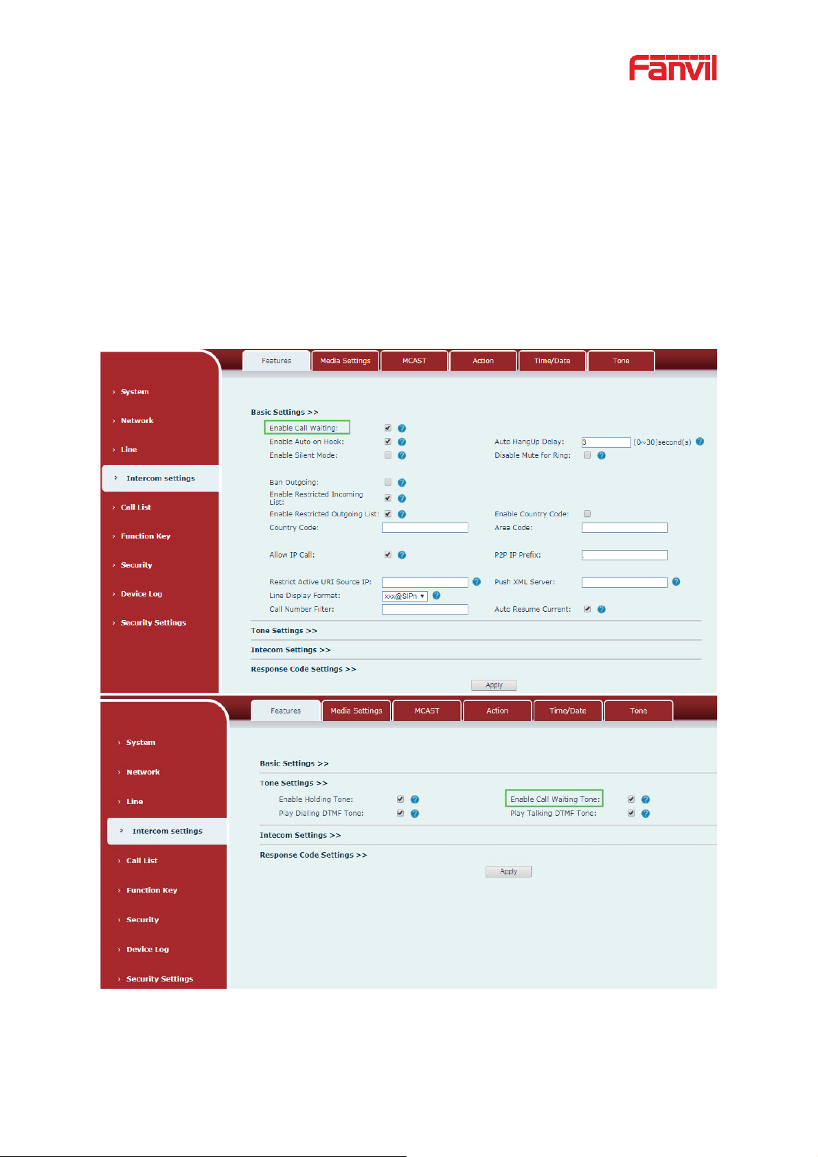
7.5 Call Waiting
z Enable call waiting: new calls can be accepted during a call.
z Disable call waiting: new calls will be automatically rejected and a busy signal will be
prompted
z Enable call waiting ton e : when you receive a new call on the line, the device will beep.
Users can enable/disable call w aiting in the device interface and the web interface.
z Web interface: enter [Intercom Setting] >> [Features], enable/disable call w a it ing,
enable/disable call waiting tone.
Figure 8 - Call Waiting
11
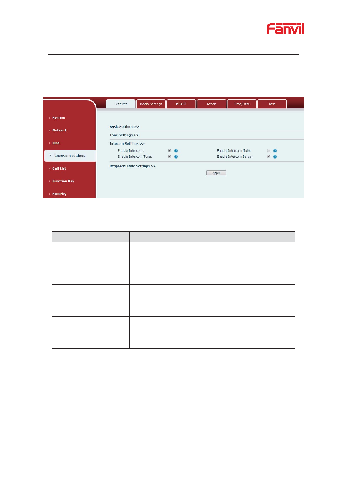
Parameters
Description
Enable Intercom
When intercom is enabled, the device will accept the
incoming call request with a SIP header of Alert-Info
instruction to automatically answer the call after
specific
delay.
Enable Intercom Mute
Enable mute during intercom mode
Enable Intercom
If the incomin
plays the
intercom tone.
Enable Intercom Barge
If enable intercom barge, the device answers the intercom
call automatically while it is in a call. If the current call is
intercom call, the dev ice will reject the second intercom call.
8 Advance Function
8.1 Intercom
The equipment can answer intercom calls automatically.
Figure 9 - Intercom
Table 4 - Intercom
g call is intercom call, the device
Tone
a
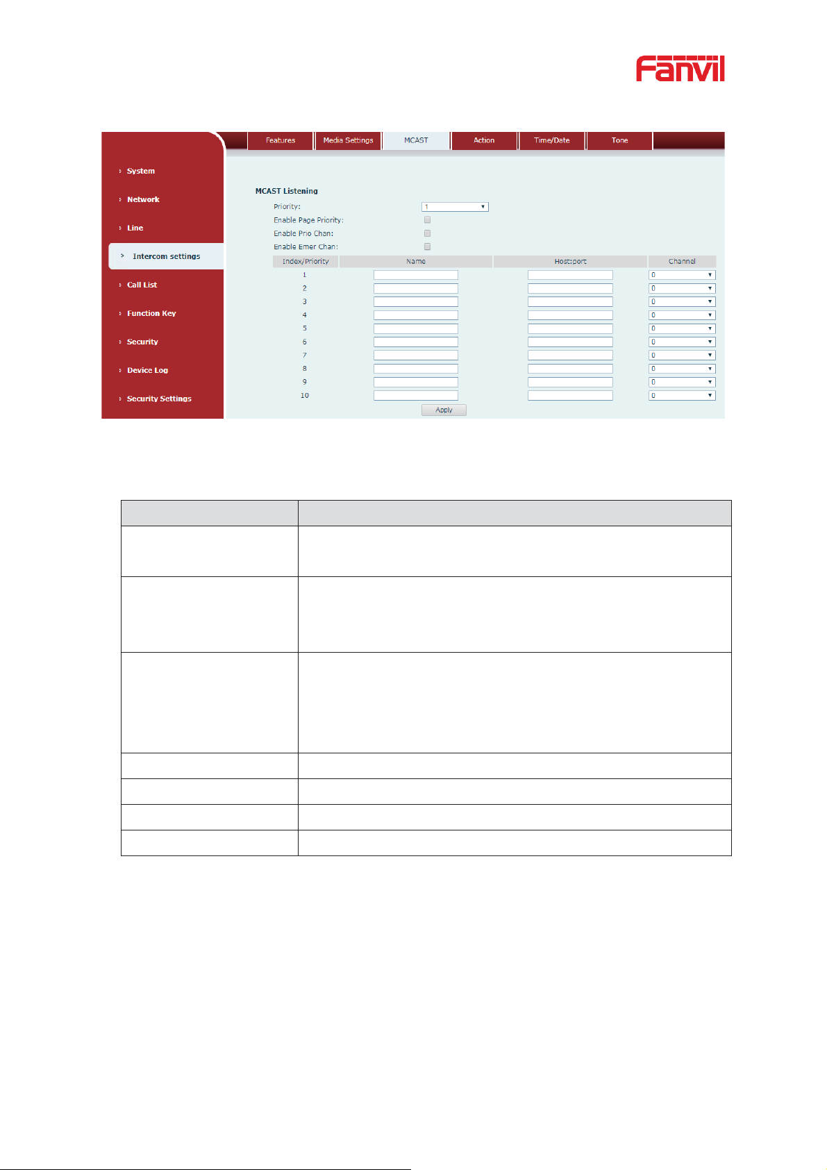
8.2 MCAST
This feature allows the user to make some kind of broadcast call to people who are in the
multicast group. The user can configure a multicast DSS Key on the device, which allows the
user to send a Real Time Transport Protocol (RTP) stream to the pre-configured multicast
address without involving SIP signaling. You can also configure the device to receive an RTP
stream from the pre-configured multicast listening address without involving SIP signaling. You
12
Parameters
Description
Priority
Define the current call’s priority, 1 means the highest priority and
10 means the lowest.
Enable Page Priority
If enable page priority, the device will receive the multicast from
address with higher priority, regardless of which of the two
multicast groups sending the multicast first.
Enable Prio Chan
If enable this option,
only multicast with the same port and
channel can be connected. Channel 24 has the higher priority, its
priority is higher than 1
23; Set channel value to be 0, it means no
channel is used.
Enable Emer Chan
When enabled, channel 25 has the high est prior ity
Name
Set the multicast server name.
Host:port
Set the multicast server’s multicast IP address and port.
Channel
0-25 (24 priority channel,25 emergency channel).
can specify up to 10 multicast listening addresses.
Figure 10 - MCAST
Multicast˖˖
Table 5 - MCAST
the
-
Send multicast:
z Go to web page of [Function Ke y] >> [Function Key Settings], select the type to be
multicast, set the multicast address, and select the codec.
z Click Apply.
z Press the DssKey of Multicast Key which you set.
Receive multica st :
z Set up the name, host and port of the receiving multicast on the web page of
 Loading...