

Fanvil G200S User Manual

[键入文字]
G200S VoIP
Gateway User Manual

[键入文字]
Safety Notices
1. Please use the power adapter that this device specified. If you have to use other manufacturers
‘power adapter because of the special circumstances, please make sure the voltage and current provided
in accordance with the provisions of this device. At the same time, we device you to use the power adapter
which passed the safety certification devices, otherwise may cause fire or get an electric shock. When
using this device, please do not damage the power cord, forcibly twisted, stretch pull or strapping, it
cannot be pressured under heavy weights or clipped in the goods , or that may cause the power cord is
damaged, and then resulting in fire or electric shock.
2. Before you use this device, please confirm the temperature and humidity of environment that the
device is working in conform to what it needs.(If you move this device from the air conditioning room to
natural temperature environment, the device may cause surface or internal components produce
condense water vapor, please wait until this device natural drying and then open the power to make the
device to work.)
3. Non technical service personnel must not remove or repair the device, otherwise improper repair
or failure may cause electric shock, fire, etc, and lead to injury accident, your device warranty also will be
invalid.
4. Please do not put your fingers, pins, wire or other metal objects, foreign body in the vents and gaps.
It may be the cause of the current through the metal or foreign body, then make an electric shock, and
lead to injury accident. If foreign bodies or a similar object fall into the device, please stop using it.
5. Please do not discard or put the device package that be packed in plastic bags on where the young
children can get it, if the young children with them on the head, it may block their nose and mouth, thus
lead to suffocation.
6. Please operate this device with correct operational method and position, if you use this device in
bad posture for a long time, there may be some effect on your health.
7. Please use the device according to the indicating method of this user manual, otherwise may
damage the device.

[键入文字]
TABLE OF CONTENT
I. ABOUT DEVICE ................................................................................................................................. 5
1. DEVICE APPEARANCE .......................................................................................................................... 5
2. INDICATOR LIGHTS DESCRIPTION ............................................................................................................ 5
3. INTERFACE AND BUTTONS DESCRIPTION ................................................................................................... 6
II. GETTING STARTED ............................................................................................................................ 7
1. CONNECTING THE POWER AND THE NETWORK ................................................................................ 7
1) Connecting the Network ............................................................................................................ 7
2) Connecting the Power ................................................................................................................ 7
III. BASIC PHONE OPERATION ............................................................................................................. 8
1. CALL TRANSFER ................................................................................................................................. 8
2. CALL HOLD ...................................................................................................................................... 8
IV. WEB CONFIGURATION .................................................................................................................. 9
1. WAYS TO CONFIGURE .......................................................................................................................... 9
2. PASSWORD CONFIGURATION ................................................................................................................. 9
3. BROWSER CONFIGURATION .................................................................................................................. 9
4. WEB PAGES FUNCTION EXPLANATION .................................................................................................. 10
(1) Status ................................................................................................................................... 10
a) Overview .............................................................................................................................. 10
b) Routes .................................................................................................................................. 11
c) System Log ........................................................................................................................... 11
(2) System ................................................................................................................................. 12
a) System ................................................................................................................................. 12
b) Administration ..................................................................................................................... 14
c) Time Synchronization ........................................................................................................... 14
d) Backup/Flash Firmware ........................................................................................................ 15
e) Auto Provision ...................................................................................................................... 16
f) Debug .................................................................................................................................. 19
g) Reboot ................................................................................................................................. 19
(3) Network ............................................................................................................................... 20
a) WAN .................................................................................................................................... 20
b) Static Routes ........................................................................................................................ 22
c) Diagnostics ........................................................................................................................... 22

[键入文字]
d) QoS ...................................................................................................................................... 25
(4) VoIP ..................................................................................................................................... 26
a) Line1 & Line2 ....................................................................................................................... 26
b) Common .............................................................................................................................. 31
c) Dial Peer .............................................................................................................................. 32
(5) Phone .................................................................................................................................. 33
a) Audio ................................................................................................................................... 33
b) Call Feature .......................................................................................................................... 34
c) Dial rules .............................................................................................................................. 36
(6) Logout .................................................................................................................................. 38
V. APPENDIX ...................................................................................................................................... 38
1. SPECIFICATION ................................................................................................................................ 38
a) Hardware ................................................................................................................................ 38
b) Voice Features ......................................................................................................................... 38
c) Network Features .................................................................................................................... 39
d) Maintenance and Management ............................................................................................... 39
2. USING PLACE .................................................................................................................................. 40
3. COMMON PROBLEMS ....................................................................................................................... 40
[键入文字]
5 / 41
I. About Device
G200S is a new VoIP gateway, its core part is a proven solution for VOIP, and so the performance
is stable and reliable. Compact appearance, intelligent software and simple interface, making IP
gateway no longer limited to enterprise applications, but also for ordinary home users.
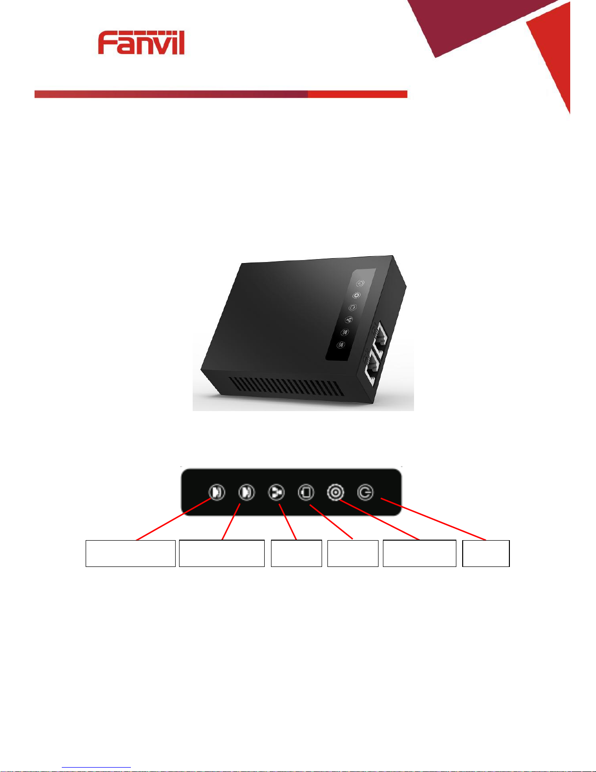
1. Device Appearance
2. Indicator Lights Description
After you insert the 12V DC power adapter to this device, power light starts to work, analog phone
light comes on, then off! Registered light twinkles for a moment, WAN light and LAN light will be
twinkling and then enter standby mode, when you pick up the analog phone, the analog phone light will
keep on, when you hang up, the light off!
Analog phone 1
WAN
LAN
Registered
Power
Analog phone 2
[键入文字]
6 / 41
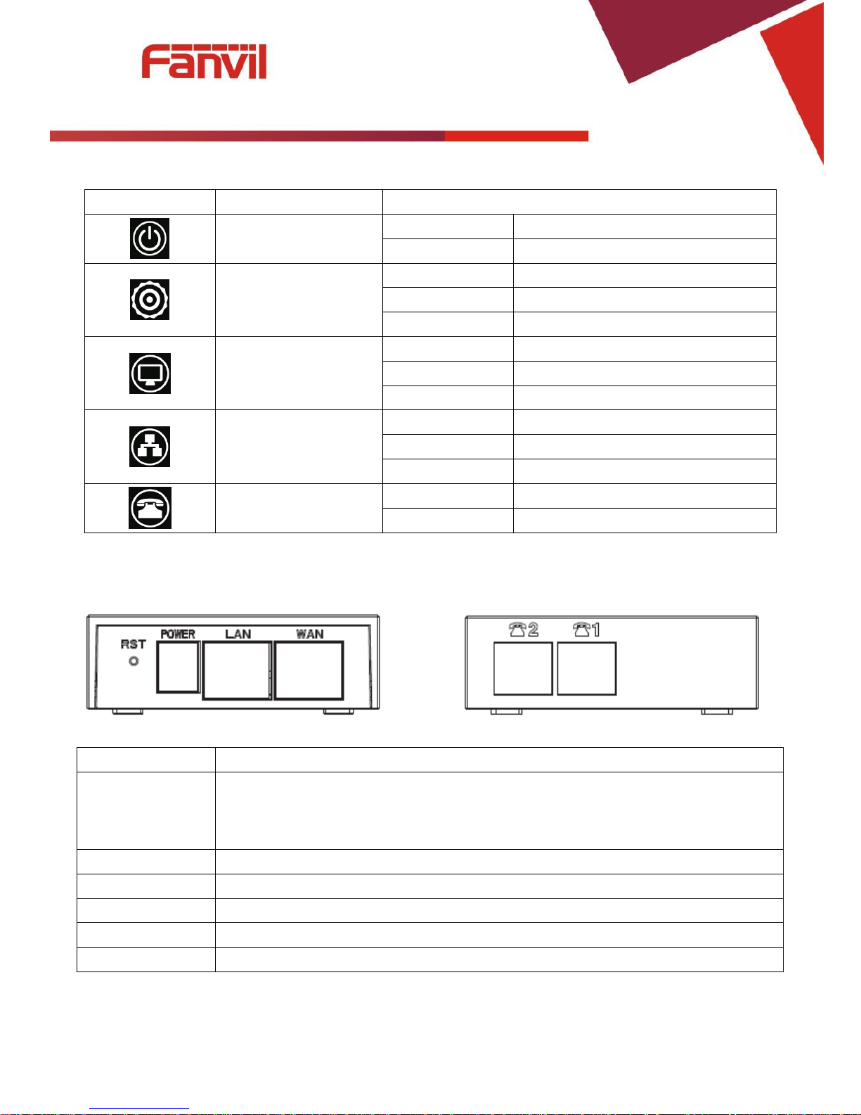
Indicator lights
Description
Function
Power Light
off
Power is invalid.
on
Power supply is normal.
SIP Registered Light
off
SIP is not registered.
twinkle
SIP registration is failed.
on
SIP registration is successful.
LAN Light
off
LAN port is not connected.
twinkle
LAN port is transmitting data.
on
LAN port connection is normal.
WAN Light
off
WAN port is not connected.
Twinkle
WAN port is transmitting data.
on
WAN port connection is normal.
Analog Phone Light
off
Phone is in standby or not connected.
on
Phone is being off hook.
3. Interface and Buttons Description
Description
Function
RST
Restore Default button. When the device is working properly, if you press this button
with a sharp object (such as a pencil) until the CPU fast twinkling (about 5
seconds).Restore function will take effect after you release it.
POWER PORT
Connecting to a power source.
LAN PORT
Connecting to a computer or a PBX and so on.
WAN PORT
Connecting to the network.
FXS1
Connecting to the analog phone.
FXS2
Connecting to the analog phone.
[键入文字]
7 / 41
II. Getting Started
Before you start using the G200S_VoIP gateway, please make the following installation:
1. Connecting the Power and the Network
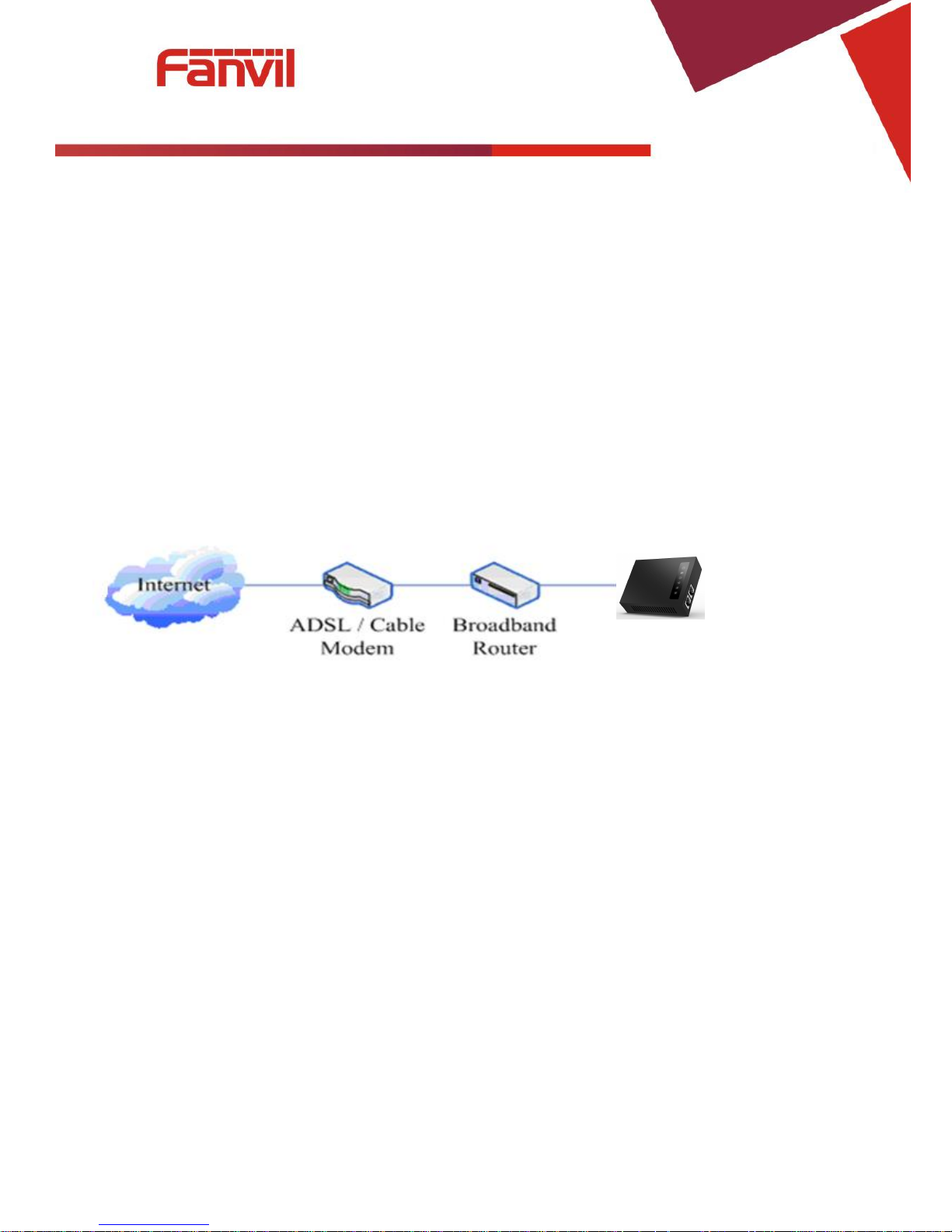
1) Connecting the Network
Before this step, please make sure your environment can satisfy the requirement of broadband
network access.
a) Broadband Router
Please connect one end of the network cable to the device's WAN port and the other end connect to
your broadband router's LAN port. Now you have completed the network hardware connection. In most
of the cases, you need to set your device's network as the DHCP mode. (The default mode of the device
is DHCP)
b) No Broadband Router
Please connect one end of the network cable to the device's WAN port and the other end connect to
your broadband modem LAN port. Now you have completed network's hardware connection. In most of
the cases, if you are using TV cable broadband, you need to set your device's network as the DHCP mode;
If you are using ADSL, you'll need to set your device's network as the PPPoE mode. Detailed setting
methods, please refer to the IV. Web Configuration.
2) Connecting the Power
Before proceeding with this step, please make sure your power connector and electrical outlet for the
agreement, at the same time, the voltage and current are also conform to what the device need.
a) Put the DC port connect to the power port that on the back of the device.
b) Put the AC adapter plug connect to an electrical outlet, the device starts to boot.
c) At this point, all of your indicator lights (except the power light) will twinkle together. After the boot
is completed, the indicator lights will be on according to your current configuration. (If your lights is
unnormal, we need to further configure your network online mode)
d) If the device has landed on the server, you can start a call right now.
G200S

[键入文字]
8 / 41
III. Basic Phone Operation
1. Call Transfer
a) Blind Transfer:
During a conversation, you press FLASH (Flash) button, enter * and the number you want to transfer,
then press [#] key to confirm, you can transfer the current call to the third party. (In order to use the
feature, you must enable the gateway Call Waiting function and Call Transfer function)
b) Attended Transfer:
During a conversation, you press FLASH (Flash) button, enter the number you want to transfer ,wait
until telephone connected, hang up directly, you can transfer success. (In order to use the feature, you
must enable the gateway Call Waiting function and Call Transfer function)
※:1. Call Transfer function is implemented under certain condition: there is one way of the two calls is
in idle state.
2. The call between Gateway (transfer side) and phone A is established, then the gateway and the
phone C start another call, now you hang up the phone A, the gateway still can initiate a transfer.
3. Only your network phone traffic service providers support the (RFC3515), can this function work
properly
2. Call Hold
Call Hold and Set Aside
During a conversation, you can press FLASH button, then enter the number to dial and the [#] key to
confirm. You can keep your current call and build the third party at the same time. If you press the FLASH
(flash) button again, you can switch back. You can only talk with one side while other parties cannot hear
your conversation or talk with you. During a conversation, if you press the [*] button, the device will enter
the three-party call mode. (To use this feature, you must enable the Call Waiting function of the gateway.
To achieve the three-way calling mode, you must enable the Gateway Three Way Call function)
Call Hold and Accept Call Waiting
During a normal conversation, if there is third-party dial-in, the handset will be heard beep ~
beep ~ tips, you can use FLASH (flash) button to accept the call waiting. If you press this button again,
you can switch back. You can only talk with one side while other parties cannot hear your
conversation or talk with you. (To use this feature, you must enable the Call Waiting function of the
gateway)

[键入文字]
9 / 41
IV. Web Configuration
1. Ways to Configure
G100S_VoIP gateway offers two different configure ways to different users:
● Use web browser: the computer users who are familiar with the operation of computers.
(Recommended use)
● Use the telnet tool: command line users.
2. Password Configuration
The setting of the device’s browser and command-line can be divided into two login modes: user
mode and supervisor mode, under the manager mode, you can view and edit all of the options; while the
<Auto Provision> option cannot be viewed under the user mode.
When a tip: ‘Please enter your password’ appeared on the device, you enter different information will
into different modes:
User mode:
Username: admin
Password: admin
Manager mode:
Username: root
Password: admin
3. Browser Configuration
When the device and computer are connected to the network successfully, you enter the device
WAN port IP address in the browser (gateway IP address can be get by dialing * 111 #)
http://xxx.xxx.xxx.xxx / to see the web management interface login page (as shown below). Enter
username and password , click【Login】button ,you will enter the setting pages .
If you have not save your settings, the settings will be restored to the previous state unchanged
when you boot phone next time .In order to save your settings, please click the <Save> button that
belongs to configuration settings in the System , after this process ,your device configuration will take
effect immediately without reboot again.
[键入文字]
10 / 41
4. WEB Pages Function Explanation
(1) Status
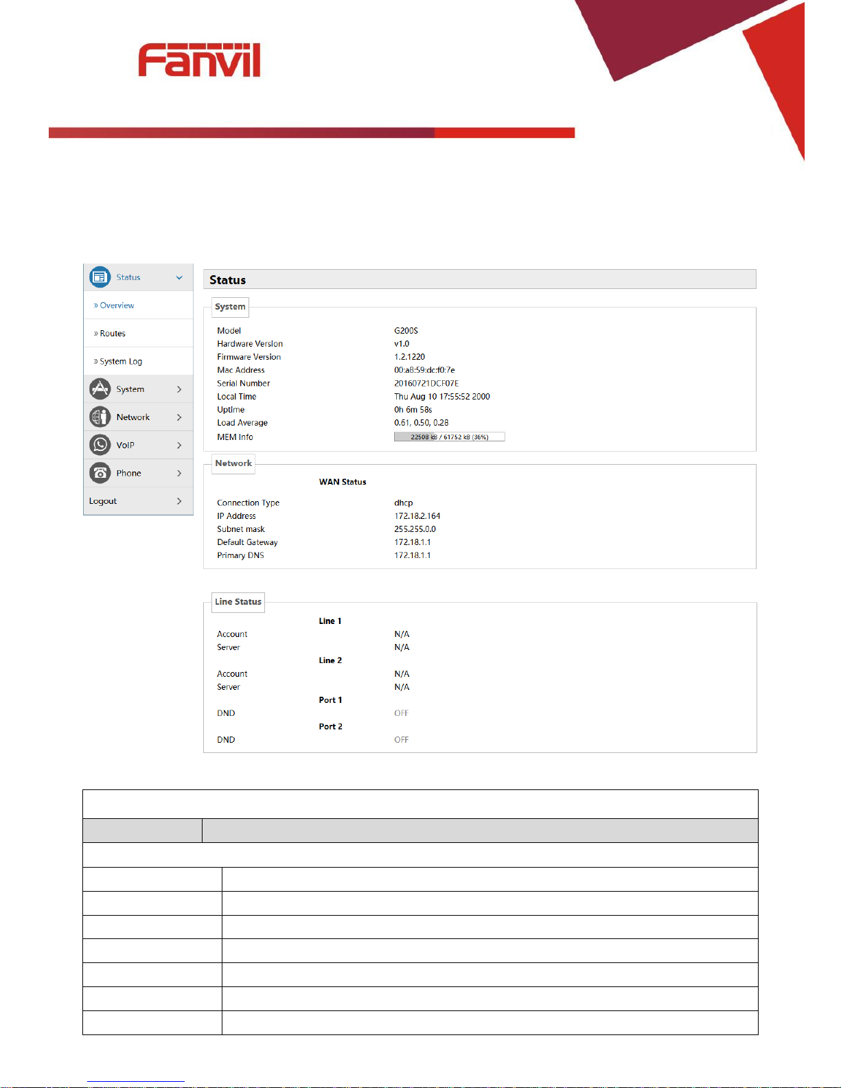
a) Overview
Overview
Name
Explanation
System
Model
Displays device model.
Hardware Version
Displays device hardware version.
Firmware Version
Displays device software firmware version number.
MAC Address
Displays the current MAC address.
Serial Name
Displays device serial number.
Local Time
Displays the current system time
Uptime
Displays device runtime
[键入文字]
11 / 41
Load Average
Displays the current average load value
MEM Info
Displays the current memory status
Network(WAN Status)
Connection Type
Displays the current networking way.
IP Address
Displays the current IP address.
Subnet Mask
Displays the current subnet mask.
Default Gateway
Displays the default gateway.
Primary DNS
Displays the primary DNS.
Line status
Displays the current SIP line 1-2 registries number 、server and status.
DND
Open this option, any dial-in call will be blocked, the caller will be prompted that the
device cannot be used, but you can establish a call with the device. (Port1 or Port2)
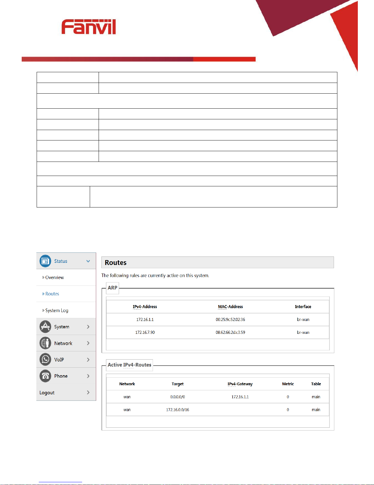
b) Routes
With this function, you can see the ARP table in the routes. The hosts IP MAC information that had
connected with the device recently will be stored in the ARP list.
c) System Log
It displays activity information of the system.
[键入文字]
12 / 41
(2) System
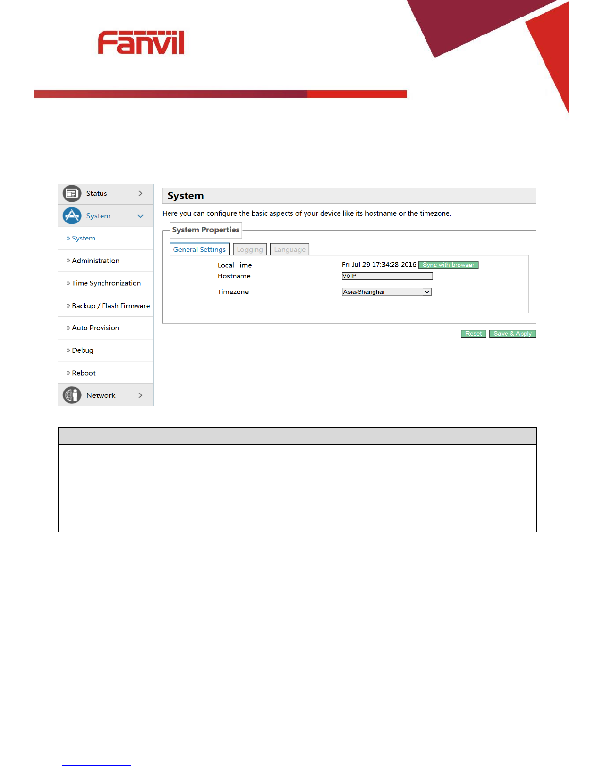
a) System
General Settings
Name
Explanation
General Settings
Local Time
Displays the current system time
Hostname
Name of the device, similar to the computer’ name. The default is VoIP, you can
modify it by yourself.
Timezone
Set the time zone of the area where you are.
[键入文字]
13 / 41
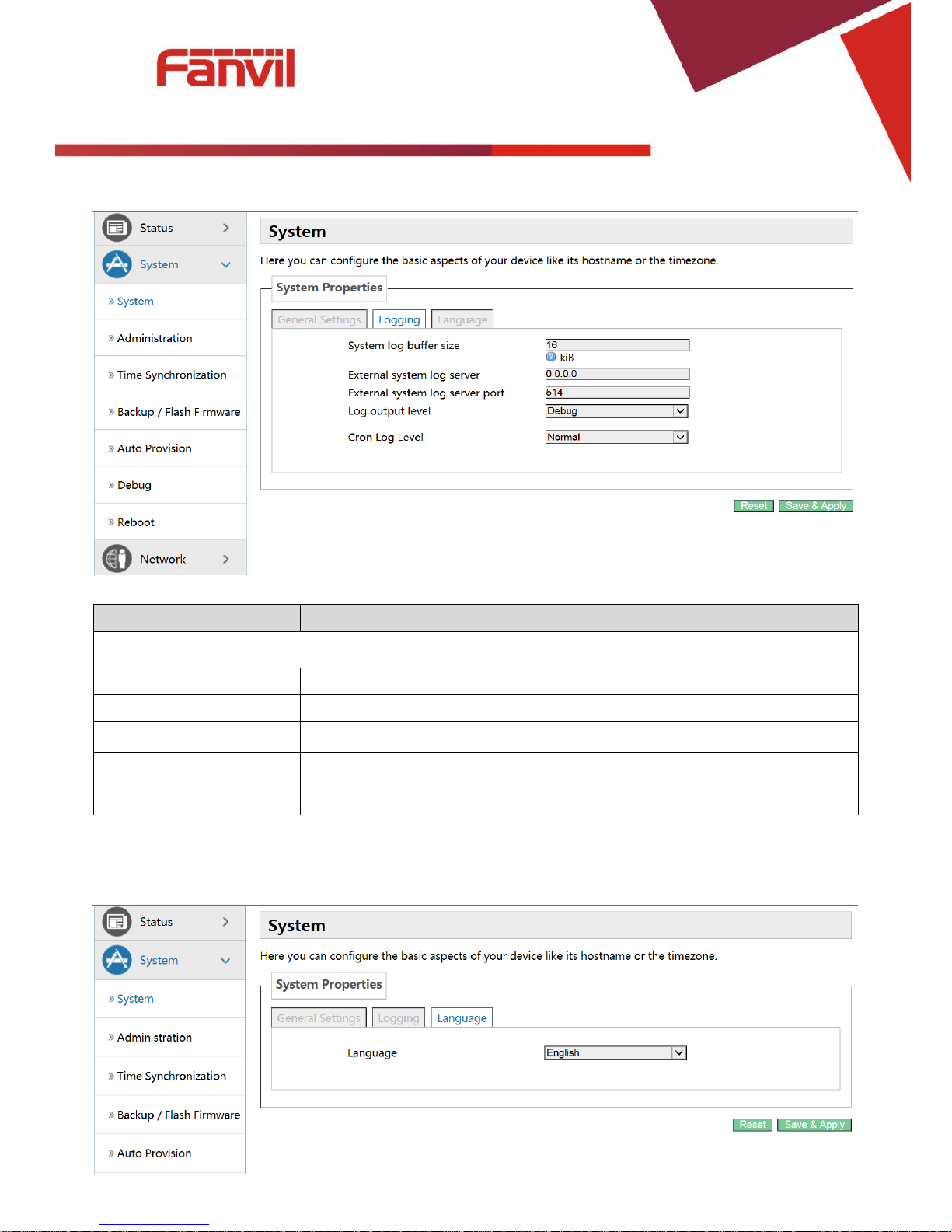
Logging
Name
Explanation
Logging
System log buffer size
Set the log buffer size.
External log system server
Set the address of the external log server.
External Log server port
Set the port of the external log server.
Log output level
Set the level of log output.
Cron log level
Set the level of Cron log.
Language
In this interface , you can configure the language that the device currently uses.
 Loading...