


THANK YOU
FANTIC WANTS TO THANK YOU
for choosing one of its products.
We recommend that you read this manual before driving your vehicle. It contains information, advice and warnings on the
vehicle maintenance and use. The instructions in this manual have been prepared to give you a simple and clear guide for
use. We are sure that taking it into consideration you will gain confidence with your new vehicle, which you can use for a
long time and with full satisfaction.
IT
EN
DE
FR
1


TABLE OF CONTENTS
THANK YOU ....................................................................................................................... 1
INTRODUCTION ................................................................................................................. 7
Manufacturer data and edition ................................................................................................................................7
SYMBOLS USED ................................................................................................................. 9
GENERAL WARNINGS .........................................................................................................11
Motorcycle care ......................................................................................................................................................11
Carbon monoxide ................................................................................................................................................... 11
Fuel .......................................................................................................................................................................... 11
Hot components ..................................................................................................................................................... 11
Used engine and gearbox oil .................................................................................................................................12
Brake fluid ...............................................................................................................................................................12
Electrolyte and hydrogen gas from the battery ...................................................................................................13
Kickstand .................................................................................................................................................................13
Precautions and general warnings .......................................................................................................................13
FUNDAMENTAL SAFETY RULES ...........................................................................................15
Behaviour and driving ............................................................................................................................................ 15
Clothing ...................................................................................................................................................................24
Tips to prevent theft ...............................................................................................................................................24
Parking ....................................................................................................................................................................24
Transport .................................................................................................................................................................24
Silencer ....................................................................................................................................................................25
IT
EN
DE
FR
GENERAL CONTENT AND CONSULTATION ............................................................................27
Vehicle identification .............................................................................................................................................27
Main controls (Scrambler version) ........................................................................................................................29

TABLE OF CONTENTS
Main controls (Flat Track version) .........................................................................................................................31
Main controls (Rally version) .................................................................................................................................33
Panel commands ....................................................................................................................................................35
Dashboard ...............................................................................................................................................................36
Ignition switch ........................................................................................................................................................52
Steering lock engagement .....................................................................................................................................53
Horn button ............................................................................................................................................................53
Turn signal switch ...................................................................................................................................................54
Light switch .............................................................................................................................................................54
High beam flashing button ....................................................................................................................................55
Start button .............................................................................................................................................................55
Engine stop button .................................................................................................................................................56
ABS system ..............................................................................................................................................................57
Saddle opening .......................................................................................................................................................59
Refuelling ................................................................................................................................................................60
Vehicle inactivity .....................................................................................................................................................61
Vehicle washing ......................................................................................................................................................62
MAINTENANCE ..................................................................................................................65
Introduction ............................................................................................................................................................65
Preliminary checks .................................................................................................................................................65
Engine oil ................................................................................................................................................................67
Tires .........................................................................................................................................................................70
Spark plug ...............................................................................................................................................................73
Air filter ....................................................................................................................................................................73
Coolant ....................................................................................................................................................................73
Braking system .......................................................................................................................................................74
Suspensions (Scrambler/Flat Track versions) ......................................................................................................76

TABLE OF CONTENTS
Suspensions (Rally version) ...................................................................................................................................78
Clutch lever and gearbox .......................................................................................................................................83
Chain .......................................................................................................................................................................84
Battery .....................................................................................................................................................................86
Fuses and relays .....................................................................................................................................................87
Lights and turn signals ...........................................................................................................................................88
Rear-view mirrors ...................................................................................................................................................89
MAINTENANCE TABLE ........................................................................................................90
Scheduled maintenance table ..............................................................................................................................90
Recommended products table ..............................................................................................................................95
TECHNICAL DATA ...............................................................................................................98
IT
EN
DE
FR


INTRODUCTION
This manual is an integral part of the vehicle and if the vehicle should be resold, it must be delivered together with the
vehicle.
Fantic Motor reserves the right to modify and make changes, at any time and without notice, to the models described,
specifications and design data, guaranteeing the essential characteristics described and illustrated herein. This publication,
or part of it, cannot be reduced or translated without the company’s approval. Reproduction of the contents used in this
manual without the Manufacturer’s permission is prohibited. Fantic Motor assumes no responsibility for printing errors
and omissions. All rights reserved.
MANUFACTURER DATA AND EDITION
Fantic Motor
Via Tarantelli, 7
31030 - Dosson di Casier (TV) Italy
Tel. +39 0422 634192
Fax +39 0422 1830124
E-mail: info@fanticmotor.it
www.fanticmotor.it
Edition: 00/2019.
IT
EN
DE
FR
7


SYMBOLS USED
The symbols indicated in the booklet are very important. They are used to highlight parts of text to which it is necessary to
pay more attention. Read this manual carefully before starting the engine. Your safety and that of others does not depend
only on your quickness of reflexes and agility, but also on your knowledge of the vehicle, its condition and your knowledge
of the rules for safe driving. We therefore recommend that you familiarize yourself with the vehicle so that you can move in
all driving situations with mastery and safety.
In this booklet you will find notes to warnings preceded by the following symbols:
Important safety regulations for the vehicle and the driver.
Information notes on the vehicle use and characteristics.
IT
EN
DE
FR
9


GENERAL WARNINGS
MOTORCYCLE CARE
Fantic Motor recommends using appropriate vehicle care products. Using products that contain alcohol, nitro diluents,
cold detergents, fuels or similar can ruin and/or damage vehicle components.
Regular care preserves the aesthetic and functional quality of your vehicle for a long time.
CARBON MONOXIDE
The exhaust fumes contain carbon monoxide, a poisonous gas that can cause death. Therefore, for certain
operations, make sure you are in an open space, or in a suitable and well-ventilated room, never in enclosed
spaces. If operating in enclosed spaces, use an evacuation system for the exhaust fumes.
FUEL
PETROL FUEL TYPE
E5 E10
The fuel used is extremely flammable and can become explosive under certain conditions. Refuelling and
maintenance operations must be carried out in a ventilated area and with the vehicle switched off. Do not
smoke during refuelling and near fuel vapours; avoid contact with open flames, sparks and any other source
that could cause ignition or explosion.
Do not disperse in the environment and keep away from children.
IT
EN
DE
FR
HOT COMPONENTS
The engine and certain components become very hot and remain hot for a while even when the engine is off. Before
carrying out any operation near the engine or exhaust system, wear insulating gloves or wait for their cooling.
11

GENERAL WARNINGS
USED ENGINE AND GEARBOX OIL
Used engine and gearbox oil is harmful to health, whether it is inhaled or swallowed. It is also irritating and can cause
serious consequences if it comes into contact with the skin.
Spreading and dispersion into the environment is prohibited.
If swallowed, do not induce vomiting, but go urgently to a first aid centre, indicating the cause and how the
accident occurred.
In case of contact with the skin, immediately wash the affected part with soap and water, repeating the
operation until the affected part is free from residues.
In case of contact with eyes and ears, immediately rinse the affected parts with plenty of water and urgently go
to a first aid center, indicating the cause and how the accident occurred.
In case of contact with clothing, undress and wash thoroughly with soap and water. Change the dirty cloths
which must be specifically washes as soon as possible.
Always use gloves suitable to protect your hands during the maintenance operations.
Keep out of the reach of children.
Used engine and gearbox oil must be collected in a sealed container, and delivered to the nearest service station
or at a waste oil collection centre where you will find personnel authorized to dispose of it.
BRAKE FLUID
Brake fluid may damage painted, plastic or rubber surfaces. Protect these components with a clean rag when
performing certain operations.
Always wear protective glasses and in case of accidental contact with eyes, rinse immediately with plenty of
clean, fresh water and consult a doctor immediately. Keep out of the reach of children.
12

GENERAL WARNINGS
ELECTROLYTE AND HYDROGEN GAS FROM THE BATTERY
The electrolyte of the battery is toxic and caustic. In contact with skin it can cause burns, as it contains sulphuric
acid. Wear gloves and protective clothing.
If the electrolyte liquid comes into contact with the skin, wash it thoroughly with fresh water.
Protect your eyes, as battery fluid can cause blindness. If it comes into contact with the eyes, wash thoroughly
with water for fifteen minutes and promptly contact an eye specialist.
The battery emits explosive gases, it is advisable to keep away flames, sparks and any other source of heat.
Provide adequate ventilation when servicing or recharging the battery.
Keep out of the reach of children.
The battery fluid is corrosive. Do not pour it or spread it, especially on plastic parts.
Provide for regular disposal.
KICKSTAND
Before leaving make sure that the kickstand is fully up. Do not load your weight or the passenger’s weight on
the side kickstand.
PRECAUTIONS AND GENERAL WARNINGS
IT
EN
DE
FR
Unless otherwise specified in this manual, do not disassemble any mechanical or electrical components.
13


FUNDAMENTAL SAFETY RULES
BEHAVIOUR AND DRIVING
Some safety tips are given below to avoid damage to people and/or things and to use your vehicle with an easier and safer
drive.
Vehicle use
To use the vehicle it is necessary to meet all the law requirements.
It is advisable, in order to acquire a good knowledge of the vehicle, to use the vehicle in areas without traffic or unpopulated
stretches of road.
It is advisable to always respect the highway code while driving, to avoid sudden or dangerous manoeuvres keeping both
hands on the handlebar and always keeping your feet on the appropriate footrests. Pay close attention while riding.
Do not ride the vehicle while drunk, under the influence of drugs, after taking certain medicines or in a state
of physical fatigue and drowsiness. Failure to comply with these rules is considered extremely dangerous and
could cause serious damage to property and/or people.
Evaluate and keep in consideration the conditions of the road surface, visibility and weather. In a situation not suitable for
safe driving, reduce the speed and drive carefully.
The braking effect in wet roads without ever having applied the brakes is initially less; under these conditions it is advised
to periodically operate the brakes.
Although the vehicle is equipped with an ABS system, pay attention during braking on a wet road and on an
unpaved or slippery ground.
In case the vehicle is used on roads dirty with sand, mud, snow mixed with salt, we recommend checking and if necessary
cleaning the brake discs with special non-aggressive detergents, so as to prevent the formation of abrasive agglomerates
inside the holes and an early wear of the brake pads.
Do not alter or modify in any way the original features and performance of the vehicle. The alteration or
modification of the original parts of the vehicle is prohibited by law and makes the vehicle no longer compliant
and it becomes dangerous for driving. These changes lead not only to the of the annulment of the guarantee,
but also to possible fines.
IT
EN
DE
FR
It is recommended to always comply with national and local laws and regulations regarding vehicle equipment.
15

FUNDAMENTAL SAFETY RULES
The getting on and off from the vehicle must be in complete freedom of movement and without impediments.
Go up and down only from the left side of the vehicle and with the kickstand down to prevent unbalancing or loss of
balance, causing falls or overturns.
The rider is always the first to go on and the last to go down as he/she has to govern the stability of the vehicle.
Getting on
The passenger must make the movements to get on with the utmost caution, avoiding to unbalance the rider and the
vehicle.
Place your feet on the ground and hold the vehicle in running position.
The kickstand is designed to support the weight of the vehicle and a minimum load, without rider and passenger.
If it is not possible to have both feet on the ground when getting on, keep only the right foot on the ground, as
the left side of the vehicle is “protected” from the kickstand, in case of imbalance or loss of balance.
The footboards must be extracted from the passenger and wait for him/her to get on the vehicle.
The rider must instruct the passenger on how to get on the vehicle. The passenger must climb with the utmost
caution, avoiding to unbalance the rider and the vehicle.
The passenger must always get on from the left side of the vehicle, using the left footrest.
Use the left foot to retract the lateral kickstand.
Getting off
Stop the vehicle in an area suitable for stopping or parking, ensuring that the ground is stable and free of obstacles. Fully
extend the kickstand using the left foot.
If it is not possible to have both feet on the ground when getting off, keep only the right foot on the ground, as
the left side is “protected” from the kickstand, in case of imbalance or loss of balance.
Keeping the vehicle in running position, wait for the passenger to get off the vehicle.
The passenger must always get off from the left side of the vehicle, using the left footrest.
16

FUNDAMENTAL SAFETY RULES
The rider must instruct the passenger on how to get off the vehicle. The passenger must get off with the utmost
caution, avoiding unbalancing the rider and the vehicle.
Do not get off the vehicle jumping or by stretching the leg to touch the ground. The stability and balance of the
vehicle would be compromised.
Tilt the vehicle making the kickstand touch the ground. Get off the vehicle and turn the handlebar completely to the left.
Make sure that the vehicle is stationary and stable.
Do not lift the vehicle grasping the license plate holder frame, in order to avoid damage.
IT
EN
DE
FR
17

FUNDAMENTAL SAFETY RULES
Starting
Release the steering lock turning the key clockwise and get
on the vehicle assuming the correct posture, making sure
that the kickstand is completely retracted.
If the kickstand is lowered, the vehicle can be started
only with the gearbox in neutral. If you try to engage
the gear the vehicle will switch off.
Apply the front and/or rear brake.
Pull the clutch lever and make sure that the gearbox is in
neutral.
18

FUNDAMENTAL SAFETY RULES
Turn the key to “ON” and wait a few seconds to load the
standard parameters on the dashboard display.
Press the engine stop button “A” and then press the start
button “B” once.
It is advisable to warm up the engine well, proceeding
for the first kilometres at reduced speed. Do not
start abruptly with the cold engine.
If the fuel reserve warning light comes on, refuel as
soon as possible.
IT
EN
DE
FR
A
B
19

FUNDAMENTAL SAFETY RULES
Starting
After starting the vehicle and warming the engine well,
operate the clutch lever and engage the first gear pressing
the gear lever downwards. The neutral indicator light will go
off on the dashboard.
Releasing the clutch slowly, gradually accelerate to allow
the vehicle to move forward.
20

FUNDAMENTAL SAFETY RULES
Gearbox use
To change gears, release the throttle control knob, operate
the clutch lever and raise the gearbox pedal upward to shift
up and/or down to shift down.
If you are a beginner in driving the vehicle, it is
important to familiarize yourself with the vehicle
controls and its functions.
Shift one gear at a time. Upshifting or downshifting
the gearbox more than a single gear at a time may
cause the engine to run out of speed and risk to
exceed the maximum speed allowed by it.
IT
EN
DE
FR
21

FUNDAMENTAL SAFETY RULES
Engine stop
To stop the vehicle and the engine, apply the front and/or
rear brake until the vehicle is stopped. Set the shift lever to
neutral.
Do not intervene on the engine stop switch when the
vehicle is running, this would cause the engine to
stop; this can damage the engine and above all may
cause loss of control of the vehicle.
Only after these operations, press the engine stop button
and turn the key counterclockwise to “OFF”.
If you forget the key turned to “ON”, the battery
charge level will decrease until it is down and will
need to be replaced.
When the vehicle is turned off, do not release the
clutch too quickly or suddenly. It could cause the
engine to stop or an unintended wheelie of the
vehicle.
Avoid sudden stops or sudden vehicle slow-downs.
22

FUNDAMENTAL SAFETY RULES
Running-in rules
When using the vehicle the first few times it is essential to carry out a running-in period, for the correct operation and
duration of the engine. During this period, it is necessary to follow certain rules in order to prepare the engine and vehicle
components for subsequent maximum performance (after running-in).
The best performance will be achieved only after having completed the inspection at the end of the running in.
The following tips are indicative and can help the user to perform a good running-in.
It is important to stress the engine and vehicle components appropriately, but it is necessary not to exceed or fail to do this
because in both cases the engine and the vehicle components would be affected. Do not make sudden accelerations and
gradually change the speed.
Full acceleration is allowed, but it is necessary not to travel too long and at full speed.
When driving on mountain roads, be careful not to force the engine, brakes and suspension. It is more suitable to travel
on roads with moderate curves and hills where engine, brakes and suspensions alternate periods of stress to periods of
reduced or no stress.
The brake pads at the purchase are new and the friction surface initially does not make perfect friction on the discs;
to be fully operative, it must be run in so that is perfectly adhering to the disc during braking. The running-in requires
approximately 200 km (125 mi) of urban route.
In this period, consider longer braking distances and use the brake lever with greater strength.
Abrupt braking and prolonged periods are to be avoided.
During the first 1000 km (600 mi) check the maintenance operations required for this mileage.
At the estimated mileage, perform the checks in the “Scheduled Maintenance Table” at an authorized Fantic
Motor Service Center. Check and carry out these operations to avoid damage to the vehicle, to others and to
yourself.
IT
EN
DE
FR
Failure to comply with these rules can negatively affect the subsequent performance of the engine and vehicle
components in general.
23

FUNDAMENTAL SAFETY RULES
CLOTHING
Always wear and fasten the helmet before starting to ride the vehicle. The helmet must be approved, intact and with the
visor intact and clean. Wear appropriate protective clothing and no hanging accessories that could create problems when
riding the vehicle. Do not wear or carry sharp objects as they are potentially dangerous in the event of a fall.
All these recommendations also apply to the passenger.
TIPS TO PREVENT THEFT
Never leave the ignition key on and always use the steering lock. Park the vehicle in a safe place, possibly in a garage or in
a monitored place. Check that the documents and the circulation tax are in order.
PARKING
Choose the parking zone carefully and with attention. It is very important to respect the road signs and the indications
given below.
Do not park the vehicle placing it against the walls or laying it on the ground. Make sure that the parking area is
solid and level.
Make sure that parts subject to high temperatures (silencer, engine, radiator, brake discs, etc.) are not dangerous
for people and the surrounding environment.
Never leave the vehicle on and unattended with the key inserted.
TRANSPORT
Before transporting the vehicle, the fuel tank must be completely emptied. Avoid accidental fuel leaks and check that the
components are completely dry. The vehicle must be firmly secured, with the first gear engaged and in running order.
In the event of failure, do not perform towing or unsafe and risky procedures that may endanger people and/or
things. This would result in the risk of causing accidents or damage to the vehicle.
24

FUNDAMENTAL SAFETY RULES
SILENCER
This component, with regard to exhaust gas, has the task of oxidizing carbon monoxide converting it into carbon dioxide,
of transforming unburnt hydrocarbons into water vapour and reducing nitrogen oxides converting them into oxygen and
nitrogen.
During the vehicle use, the part of the exhaust system corresponding to the catalytic element can take a bright
red colour: this colour variation is absolutely normal and indicates a correct operation of the catalyst.
Avoid stopping or parking the vehicle near places where there is dry brushwood.
Avoid places accessible to children and/or people.
The silencer reaches high temperatures, so avoid any kind of contact and pay the maximum attention until it
has not completely cooled down.
It is forbidden to modify, alter or tamper with the exhaust system in any way.
Do not use leaded petrol as it will ruin the catalyst.
Check that there are no holes and signs of rust or wear on the exhaust system.
Check that the exhaust system always works correctly.
In case of increased or abnormal noise, contact a Authorized Fantic Motor Center as soon as possible.
For maintenance, repair or replacement work, contact an Authorized Fantic Motor Center.
IT
EN
DE
FR
25


GENERAL CONTENT AND CONSULTATION
VEHICLE IDENTIFICATION
Frame number
Engine number
Fantic Motor vehicles are equipped with frame and engine identification numbers. It is advisable to write down the
identification numbers in the spaces indicated above, in order to remind them in case of loss or damage.
IT
EN
DE
FR
Do not modify the identification data in order to avoid serious penal and administrative sanctions. In addition,
the warranty for new vehicles will be invalidated if the frame identification number has been changed and can
not be readily determined.
27

GENERAL CONTENT AND CONSULTATION
Frame number
The frame number is punched on the steering tube on the
right side.
For the original spare parts supply this identification
number to your dealer.
Engine number
The engine number is punched on the left side of the
crankcase.
28

GENERAL CONTENT AND CONSULTATION
MAIN CONTROLS (SCRAMBLER VERSION)
6
5
4
3
1
2
22
23
21 20 19
1. Headlight
2. Left front turn indicator
3. Dashboard
4. Clutch lever
5. Left light stalk
6. Left rear-view mirror
7. Tank cap
8. Fuel tank
9. Rider and passenger saddle
10. Rear handle
11. Rear fender
12. Tail light
13. License plate holder
14. License plate light
15. Left rear turn indicator
16. Left passenger footrest
17. Left rider footrest
18. Side kickstand
7 8 9 10 12 11
18 17 16
19. Gear shift lever
20. Left radiator cover
21. Front brake calliper
22. Front speed sensor
23. Phonic wheel
15
14
13
IT
EN
DE
FR
29

GENERAL CONTENT AND CONSULTATION
24
25
36
37
38
24. Right rear-view mirror
25. Right light stalk
26. Gas command
27. Front brake master cylinder
28. Front brake lever
29. Right front turn signal
30. Engine oil cap
31. Rear brake lever
32. Rear brake oil tank
26
35
32 34 33 31 30
33. Right rider footrest
34. Rear brake master cylinder
35. Right passenger footrest
36. Rear brake calliper
37. Rear speed sensor
38. Phonic wheel
27
28
29
30

GENERAL CONTENT AND CONSULTATION
MAIN CONTROLS (FLAT TRACK VERSION)
6
5
3
4
1
2
21
22
20 19 18
1. Headlight
2. Left front turn indicator
3. Dashboard
4. Clutch lever
5. Left light stalk
6. Left rear-view mirror
7. Tank cap
8. Fuel tank
9. Rider and passenger saddle
10. Rear fender
11. Tail light
12. License plate holder
13. License plate light
14. Left rear turn indicator
15. Left passenger footrest
16. Left rider footrest
17. Side kickstand
18. Gear shift lever
7 8 9
16 17 15
10
19. Left radiator cover
20. Front brake calliper
21. Front speed sensor
22. Phonic wheel
11
14
13
12
IT
EN
DE
FR
31

GENERAL CONTENT AND CONSULTATION
35
36
37
34
31 33 32 30 29
24
23
26
25
27
28
23. Right rear-view mirror
24. Right light stalk
25. Gas command
26. Front brake master cylinder
27. Front brake lever
28. Right front turn signal
29. Engine oil #M# cap/dipstick
30. Rear brake lever
31. Rear brake oil tank
32
32. Right rider footrest
33. Rear brake master cylinder
34. Right passenger footrest
35. Rear brake calliper
36. Rear speed sensor
37. Phonic wheel

GENERAL CONTENT AND CONSULTATION
MAIN CONTROLS (RALLY VERSION)
6
5
3
4
1
2
22
23
1. Headlight
2. Left front turn indicator
3. Dashboard
4. Clutch lever
5. Left light stalk
6. Left rear-view mirror
7. Tank cap
8. Fuel tank
9. Rider and passenger saddle
21 20 19
10. Rear handle
11. Rear fender
12. Tail light
13. License plate holder
14. License plate light
15. Left rear turn indicator
16. Left passenger footrest
17. Left rider footrest
18. Side kickstand
18 17 16
7 8 9 10 12 11
19. Gear shift lever
20. Left radiator cover
21. Front brake calliper
22. Front speed sensor
23. Phonic wheel
15
14
13
IT
EN
DE
FR
33

GENERAL CONTENT AND CONSULTATION
36
37
38
24. Right rear-view mirror
25. Right light stalk
26. Gas command
27. Front brake master cylinder
28. Front brake lever
29. Right front turn signal
30. Engine oil cap
31. Rear brake lever
32. Rear brake oil tank
24
26
35
32 34 33 31 30
33. Right rider footrest
34. Rear brake master cylinder
35. Right passenger footrest
36. Rear brake calliper
37. Rear speed sensor
38. Phonic wheel
39. Number plate
25
27
28
39
29
34

GENERAL CONTENT AND CONSULTATION
PANEL COMMANDS
3 2
1
17
1. Low beam/high beam light switch
2. ABS indicator light
3. High beam flashing button
4. Ignition switch
5. Fuel reserve indicator light
6. “ADJUST” button
7. “SELECT” button
8. Turn signal indicator light
9. High beam light indicator
4
16
10. Engine indicator light
11. Engine oil indicator light (not used)
12. Neutral indicator light
13. Engine stop button
14. Gas command
15. Start button
16. ABS button
17. Speedlight switch
18. Horn button
5
7 6
8 9 10 11 12
1415 1318
IT
EN
DE
FR
35

GENERAL CONTENT AND CONSULTATION
DASHBOARD
B
A
A. Odometer
• Total trip distance recorder
• Partial trip distance recorder “A”
• Partial trip distance counter “B”
• Remaining Fuel/Distance
B. Fuel level
C. Digital voltmeter
C
E
F
G
D. Tachometer
E. Clock
F. Speedometer
G. Indicator light
D
36

GENERAL CONTENT AND CONSULTATION
Functions instructions with dashboard in stand-by
When the dashboard is off, press the adjustment button
(“ADJUST”) or the selection button (“SELECT”) to activate
the clock.
The clock will remain visible on the screen for 30 seconds
after activation.
Adjustment button instructions (“ADJUST” button)
In the main screen (ODO) press once the adjustment button
(“ADJUST”) to activate the partial trip distance recorder A.
Press and hold the adjustment button (“ADJUST”) for three
seconds to change the Odometer measurement units, from
kilometres (“km”) to miles (“mile”), and the speedometer
measurement units, from kilometres per hour (“km/h “) to
miles per hour (“ MPH “), and vice versa.
IT
EN
DE
FR
37

GENERAL CONTENT AND CONSULTATION
In the partial trip distance counter A screen press once the
adjustment button (“ADJUST”) to activate the partial trip
distance counter B.
Press and hold the adjustment button (“ADJUST”) for three
seconds to reset the partial trip distance counter A.
In the partial trip distance counter B screen press once the
adjustment button (“ADJUST”) to activate the remaining
fuel/distance screen.
Press and hold the adjustment button (“ADJUST”) for three
seconds to reset the partial trip distance counter B.
38

GENERAL CONTENT AND CONSULTATION
In the remaining fuel/distance screen, press once the
adjustment button (“ADJUST”) to reactivate the main screen
(Odometer function).
Remaining distance learning procedure
Fill with fuel and, in the remaining fuel/distance screen, press
and hold the adjustment button (“ADJUST”) for ten seconds;
the symbol ODO flashes and the remaining distance is reset
to 0 and the learning is restarted.
When the fuel level reaches 0, refuel. At the end of this
operation, the ODO symbol stops flashing; this means that
the remaining distance learning has been completed.
The actual remaining distance indicated may be
different from the calculated distance depending
on the road conditions, the vehicle conditions, the
type of driving and so on. For these reasons the
remaining distance is only a reference for the rider.
IT
EN
DE
FR
39

GENERAL CONTENT AND CONSULTATION
Selection button instructions (“SELECT” button)
In the clock screen, press once the selection button
(“SELECT”) to display the battery voltage screen.
In the battery voltage screen, press once the selection
button (“SELECT”) to activate the clock.
RPM (engine speed) operating instructions
On the screen showing the remaining fuel/distance and
battery voltage, press and hold the selection button
(“SELECT”) for three seconds to display the RPM (engine
speed) screen.
In the RPM (engine speed ) screen, press and hold the
selection button (“SELECT”) to display to the remaining
fuel/distance screen and battery voltage screen.
40

GENERAL CONTENT AND CONSULTATION
On the RPM screen (engine revolutions)
When the remaining fuel level is at 1 the fuel symbol flashes
as a warning.
When the remaining battery voltage level is at 1 the Battery
symbol flashes as a warning.
IT
EN
DE
FR
41

GENERAL CONTENT AND CONSULTATION
Settings screen instructions
In the settings screen, it is possible to press the selection
button (“SELECT”) to access the settings. The settings
screen has the following order of options:
– input pulse setting (RPM function);
– tire circumference setting;
– fuel resistance setting;
– clock setting;
42
– dashboard backlight setting;
– total internal odometer screen setting;
– total external odometer screen setting.
If no action is taken within 30 seconds, the
dashboard automatically returns to display the
main screen.

GENERAL CONTENT AND CONSULTATION
Access the settings screen
On the main screen, press and hold the selection (“SELECT”)
and adjust (“ADJUST”) buttons simultaneously for three
seconds to activate the Settings screen.
Input signal setting (RPM)
Press the adjustment button (“ADJUST”) to change the
setting.
The setting digit flashes during the modification operations.
Adjustment range: 0.5, 1 ~24.
IT
EN
DE
FR
43

GENERAL CONTENT AND CONSULTATION
Press the selection button (“SELECT”) until the desired input
pulses value is reached.
It is advisable, if the exact value is not known, not to
change the preset value. In case of need, contact an
Authorized Fantic Motor Center.
The correct value is: 0,5.
Press the adjustment button (“ADJUST”) to select the correct
waveform.
The RPM pulse is defined as “Hi” (positive pulse)
and “Lo” (negative pulse).
The writing that identifies the waveform setting, flashes
during the modification operations.
If the speed (RPM) is incorrect or not correctly
displayed, select another setting and try again.
It is advisable, if the exact value is not known, not to
change the preset value. In case of need, contact an
Authorized Fantic Motor Center.
44

GENERAL CONTENT AND CONSULTATION
Check with the engine running idle if the RPM
indicator indicates a notch and if, with a slight
rotation of the gas, it indicates two. In this case,
the configuration adopted is correct, otherwise try
again.
In the event that the standard configuration values are not
successful, try the following combinations:
No. of pulses / waveform:
“1”/”Lo” , “1”/”Hi” , “2”/”Lo” , “2”/”Hi”.
After completing the settings, press one and hold the
selection button (“SELECT”) to display the next setting view.
Tire circumference compensation setting
When tires of another size are installed it is necessary
to reset the setting value.
Press and hold the selection button (“SELECT”) until
the specific value to be entered is reached. The correct
compensation value (expressed as a percentage) to be
entered can be calculated.
The calculation to define the value to insert is the following:
A ÷ B • 100%.
A. Circumference of the new tire.
B. Circumference of the original tire.
Setting values:
Scrambler version = 2202 mm;
Flat Track version = 2250 mm.
IT
EN
DE
FR
45

GENERAL CONTENT AND CONSULTATION
The number that identifies the setting flashes during
the modification operations.
Range displayed: 300~2500.
Unit of measure: 1 mm.
Tip: it is possible to define the valve as the starting and
ending point to measure the wheel circumference with a
tape measure.
Press the adjustment button (“ADJUST”) to change the
wheel circumference value.
At the end of the setting, press once and hold the selection
button (“SELECT”) to display the next setting view.
46

GENERAL CONTENT AND CONSULTATION
Press the adjustment butt o n (“ADJUST”) to change the
setting.
The number that identifies the setting flashes during
the modification operations.
Value range: 1~20 points.
Standard value to set: 9 pulses (points).
At the end of the setting, press once and hold the selection
button (“SELECT”) to display the next setting view.
It is advisable, if the exact value is not known, not to
change the preset value. In case of need, contact an
Authorized Fantic Motor Center.
Fuel resistance setting
Press the adjustment button (“ADJUST”) to select the
number to be set.
The resistance values which can be selected are:
100 Ω, 250 Ω, 510 Ω and 1200 Ω.
Correct fuel resistance value: 100 Ω.
It is advisable, if the exact value is not known, not to
change the preset value. In case of need, contact an
Authorized Fantic Motor Center.
IT
EN
DE
FR
47

GENERAL CONTENT AND CONSULTATION
After completing the setting, press once and hold the
selection button (“SELECT”) to display the next setting view.
When the fuel resistance value is changed, the
remaining distance is reset to 0 and learning is
restarted.
48

GENERAL CONTENT AND CONSULTATION
Clock setting
Press and hold the selection button (“SELECT”) and release
it when the desired digit is displayed.
During the modification, the selected digit will
continue to flash.
This is a clock with 24-hour format. The setting
follows the order from hours to minutes.
Press the adjust button (“ADJUST”) to select another digit
to change.
At the end of the adjustment, press once and hold the
selection button (“SELECT”) to display the next setting view.
IT
EN
DE
FR
49

GENERAL CONTENT AND CONSULTATION
Dashboard backlight setting
Press and hold the adjustment button (“ADJUST”) and
release it when the desired illumination value is selected.
Lighting values range from 1-5 (darker) to 5-5
(lighter). The brightness of the dashboard changes
immediately after setting the value.
At the end of the, press once and hold the selection button
(“SELECT”) to confirm and to display the next setting view.
Internal total odometer screen setting
Press once and hold the selection button (“SELECT”) to
display the next setting view.
50

GENERAL CONTENT AND CONSULTATION
External total odometer screen setting
Press and hold the selection button (“SELECT”) until the
desired digit is displayed.
Then, press the adjust button (“ADJUST”) to change the digit
to be changed.
Once the desired value has been set, press once and hold
the selection button (“SELECT”) to confirm and return to the
main screen.
Dashboard main screen after applying the customized
settings.
IT
EN
DE
FR
51

GENERAL CONTENT AND CONSULTATION
IGNITION SWITCH
The ignition switch is located at the front of the vehicle near
the dashboard.
The functions of the ignition switch are the following:
A. The handlebar is locked and the vehicle cannot be
started and the lights cannot be switched on. The key can
be removed.
B. The vehicle and the lights can not be operated and the
key can be removed.
C. The vehicle can be put into operation but the key can not
be removed.
D. The handlebar is locked and the vehicle can not be
started. The position lights of the headlight and tail light
are activated. The key can be removed.
The vehicle is delivered with two keys, one of which is spare. Keep the spare key in a place other than the
vehicle.
The lights switch off when the ignition switch is positioned on “B”.
The key, besides the ignition switch, activates the tank cap.
When the vehicle is started, the lights turn on automatically.
B
A
C
D
52

GENERAL CONTENT AND CONSULTATION
STEERING LOCK ENGAGEMENT
To insert the steering lock, turn the handlebar completely to
the left and turn the key to position “A”.
Press and turn the key anticlockwise and slowly turn the
handlebar until the key is positioned on “B”.
HORN BUTTON
Press to activate the horn.
IT
A
EN
DE
B
FR
53

GENERAL CONTENT AND CONSULTATION
TURN SIGNAL SWITCH
Press the switch to the left or right to indicate the turn.
Press the switch, bringing it to the center position to
deactivate the indicators.
LIGHT SWITCH
When the light switch is turned counterclockwise it activates
the high beam.
To reactivate the low beam light operation, turn the light
switch clockwise.
54

GENERAL CONTENT AND CONSULTATION
HIGH BEAM FLASHING BUTTON
Pressing it activates the flashing of the high beam.
It is usually used to indicate danger or emergency situations.
When the button is released, the high beam flashing is
deactivated.
START BUTTON
With the key inserted and set to “ON”, with the engine stop
button deactivated, when the button is pressed, the engine
will start.
IT
EN
DE
FR
55

GENERAL CONTENT AND CONSULTATION
ENGINE STOP BUTTON
Pressing it stops the engine.
It has the function of a safety or emergency switch.
Do not intervene on the switch when the vehicle
is running, this would cause the engine to stop.
This could result in loss of control of the vehicle,
increasing the risk of accidents and damaging things
and/or people.
56

GENERAL CONTENT AND CONSULTATION
ABS SYSTEM
The vehicle is equipped with an ABS system that operates
on both wheels. The ABS system is composed of an electrohydraulic device which limits the pressure inside the braking
system at the moment of braking. This occurs through the
detection of the tendency to block the phonic wheels “A”
(installed on the brake discs) carried out by the angular
speed sensors “B” placed on the forks.
The ABS system allows an increase in the braking stability of
the vehicle compared to a traditional braking system with
the aim of reducing the risk of falling.
Do not exceed the physical road holding limits of
the vehicle. It is the rider’s responsibility to ride at
appropriate speeds, always evaluating the weather
and road conditions. The ABS cannot compensate
for errors in judgement and/or incorrect use of the
vehicle.
When the key is turned to the “ON” position, the ABS
indicator light turns on and flashes until the vehicle
exceeds 5 km/h, and then it turns off.
In the event of a battery malfunction, the ABS
system is deactivated.
The ABS system intervenes on both wheels,
receiving information from the phonic wheels. It is
important to always check that the phonic wheels
are clean and periodically check that the distance
from the sensor is fully constant. For verification
and adjustment, contact an authorized Fantic Motor
Center.
IT
EN
B
DE
A
FR
BA
57

GENERAL CONTENT AND CONSULTATION
The ABS can be activated/deactivated by pressing, for a few
seconds, the ABS button “C”.
The ABS warning light stays on permanently if the
ABS system has been manually deactivated.
In case of failure of the ABS system, the indicator
light turns on, the vehicle retains the characteristics
of a traditional braking system. Moderate the speed
and go to an authorized Fantic Motor Center.
At low speed the ABS system is not active: pay
particular attention to the braking situations in
conditions of low grip at low speed.
C
58

GENERAL CONTENT AND CONSULTATION
SADDLE OPENING
To open the saddle, unscrew and remove the screw “A”.
Lift up and remove the saddle “B”.
Before reassembling the saddle make sure you have
not forgotten the key in the area under the saddle.
Before riding, check that the saddle has been
correctly fixed.
IT
EN
DE
A
B
FR
59

GENERAL CONTENT AND CONSULTATION
REFUELLING
To refuel, lift the cover “A”.
Insert the key “B” and turn it anticlockwise.
Lift the cap “C” and refuel.
When refuelling, do not smoke or use open flames,
avoid using electrical devices or any source that
can trigger sparks or ignition. Failure to comply
with these rules could result in a danger of fire or
explosion, causing serious damage to property and/
or persons.
Do not add additives or other substances to the fuel
during refuelling.
Avoid fuel leakage during refuelling. If you use a
funnel, make sure that it is perfectly clean.
It is recommended to use the type of fuel indicated
in the technical specifications of this manual. Do
not use different fuels, they could damage the fuel
system and compromise the operation of the engine.
After refuelling, close the cap “C”.
Turn the key “B” clockwise and then remove it.
Close the cover “A”.
The tank cap can be closed only with the key
inserted.
A
B
C
C
Make sure that the tank cap is closed.
60

GENERAL CONTENT AND CONSULTATION
VEHICLE INACTIVITY
If the vehicle should remain inactive for months it is advisable to take some precautions:
– Empty the tank completely.
– Remove the battery and charge it with a suitable battery charger every two weeks.
The battery must be kept in a dry place and at a temperature between 5-35 °C (41-95 °F). Keep the battery out of
reach of children.
– Position the vehicle with the tires raised off the ground using the appropriate supports and periodically check the tire
pressure.
– Lubricate the chain.
– Cover the exhaust terminal with a well-tied bag to prevent moisture from entering inside.
– Cover the vehicle with an appropriate sheet (in breathable material) of a size sufficient to fully cover the vehicle.
– The vehicle must be placed in an unheated place with minimal temperature variations, free from humidity and protected
from sunlight.
After the period of inactivity
– Uncover and wash the vehicle.
– Check the battery status
– Perform preliminary checks.
Take a test drive for a few kilometres (miles) at moderate speed in an area away from traffic.
IT
EN
DE
FR
61

GENERAL CONTENT AND CONSULTATION
VEHICLE WASHING
It is good that the vehicle is washed periodically to keep its components in good condition.
If the vehicle is used under the following conditions, more frequent washing is recommended:
– Areas where humidity and salinity of the atmosphere are higher than normal.
– Roads or areas where salt or de-icing chemicals are used.
– Roads or areas with the presence of industrial dust or tar stains.
– Sport use and off-road driving.
– Presence on the vehicle body of dead insects, bird excrement, etc.
It is advisable not to stop or park the vehicle under plants or trees. Certain plants or trees release residues, resins, fruits or
leaves containing substances harmful to the vehicle components and bodywork.
Do not wash in the sun, especially in summer, with the body still warm, as if the detergent dries before rinsing it could cause
damage to the paintwork.
Do not use liquids at temperatures above 40 °C (104 °F) to clean plastic components.
Do not direct air jets, steam or water at high pressure on:
– Wheel hubs.
– Handlebar switches.
– Bearings.
– Brake oil master cylinder and tanks.
– Tools and indicators.
– Exhaust system fumes outlet hole.
– Steering lock.
– Fuel tank cap or similar.
– Headlight and tail light.
– Electrical components.
– Decals.
Do not use products that contain alcohol, petrol or solvent for cleaning the saddle, rubber and/or plastic parts.
Use of unsuitable products can damage vehicle components.
The use of a jet of high pressure water can damage some components of the vehicle.
Use a jet of warm water at low pressure, rinse the vehicle thoroughly and in particular the dirtiest parts. With a soft sponge
rub all parts of the vehicle.
62

GENERAL CONTENT AND CONSULTATION
Rinse the vehicle well and thoroughly using a low pressure jet. With a chamois leather cloth, proceed to dry the vehicle.
It is possible that after the wash the braking efficiency is reduced, it is therefore recommended to dry the discs well and
wait for the pads to dry.
If the vehicle is started, proceed with caution and operate the brakes repeatedly.
Only after a scrupulous and thorough washing it is possible to proceed with the polishing phase with silicone waxes.
Do not use abrasive pastes on the vehicle, they could damage the painted parts.
Do not apply protective wax on the parts of the braking system, it could compromise their operation.
Do not pass wax on the saddle, it could damage it and make it slippery, reducing the stability of the rider’s and/
or passenger’s seat thus increasing the risk of accidents and/or damage to things and/or people.
IT
EN
DE
FR
63


MAINTENANCE
INTRODUCTION
For specific maintenance and repairs it is advisable to contact our Authorized Fantic Motor Centers, which will guarantee
an accurate and prompt service, always using original spare parts.
It is recommended, after the first hours of use, to carry out the preliminary checks.
Failure to follow these procedures can result in serious injury to persons and to the vehicle. Contact an
Authorized Fantic Motor Center if malfunctions or anomalies are found.
PRELIMINARY CHECKS
PART DESCRIPTION
Front and rear disc brake Check the levers operation, idle stroke, fluid level and check for leaks. If
necessary, top up the brake fluid.
Throttle control Make sure that the knob rotation is smooth and fluid from both directions
and that there are no jamming.
Engine oil Check the level and top up if necessary.
Wheels and tires Check the tires surface conditions, pressure, wear and the presence of
damage. Remove the trapped foreign bodies, if any.
Levers and brakes Check that it works correctly during engagement and release without
jamming, tearing or slipping. Lubricate the joints if necessary.
Clutch lever Check that it works correctly during engagement and release without
jamming, tearing or slipping. Lubricate the joints if necessary.
IT
EN
DE
FR
Handlebar Make sure that the complete rotation on both sides is free and
homogeneous and without clearance or slack.
65

MAINTENANCE
PART DESCRIPTION
Kickstand Check its rotation and sliding. Check that the spring tension returns it to
its normal position. Lubricate the joints if necessary. Check the correct
operation of the safety switch.
Fastening elements Check that there are no loose fasteners. If necessary, adjust and tighten.
Fuel tank Check the fuel level and refill if necessary. Check the correct closing of the
fuel cap and that there are no leaks in the circuit.
Engine stop switch Check the correct operation.
Start switch Check the correct operation.
Phonic wheels Check that they are perfectly clean and not damaged.
Acoustic and visual devices Check the correct operation. Replace in case of failure.
66

MAINTENANCE
ENGINE OIL
Check and verify the engine oil level every 1,000 km
(600 mi).
Check the engine oil level
Periodically check the engine oil level.
The engine oil check must be carried out with hot
engine.
Do not rest the vehicle on the side kickstand when
checking the engine oil.
Position and keep the vehicle in a vertical position and with
both wheels resting on the ground.
Start the engine and warm it up for at least two minutes at
idling speed and then turn it off: wait two minutes before
checking the oil level.
Check the oil level from the porthole.
The level must remain between the notches at the porthole.
H = MAX
L = MIN
The oil level must not go beyond the “H” marking
and must never be below the “L” marking, in order
not to damage the engine.
IT
EN
DE
FR
67

MAINTENANCE
Engine oil topping up
If after checking the engine oil level, the level is not in the
right parameters, topping up is required.
Therefore remove the oil level plug and top up.
If you use a funnel or something else, make sure of
the perfect cleaning.
Do not add additives or other substances and use
the products recommended in the “RECOMMENDED
PRODUCTS TABLE” section.
68

MAINTENANCE
Engine oil replacement
The operations for filter and engine oil replacement are complicated for an inexperienced operator. It is
advisable to contact an Authorized Fantic Motor Center if you need to remove and replace the filter and the
engine oil.
Amount of engine oil
– Total amount: 1.6 l (0.35 UK gal, 0.42 US gal)
– Without replacement of the oil filter element: 0.95 l (0.20 UK gal, 0.25 US gal)
– With replacement of the oil filter element: 1 l (0.21 UK gal, 0.26 US gal)
IT
EN
DE
FR
69

MAINTENANCE
TIRES
For tire pressure values, brand, type and dimensions refer to
the “TECHNICAL DATA” section.
Check the tire pressure at room temperature,
because if the tires are warm, the measurement will
not be correct.
The tires ambient temperature means that the
vehicle has been stationary for at least three hours
or has travelled a distance of less than 2 km (1 mi).
Check the fuel consumption and tire pressure (at room
temperature) before and after each long trip.
If the inflation pressure is too high, the irregularities
of the ground are not properly cushioned and are
then transmitted to the handlebar, compromising
road holding in turns. If the inflation pressure is
insufficient, the sidewalls of the tires work harder
and there is a risk of tire slippage on the rim or
detachment, with consequent loss of control of the
vehicle: in the event of sudden braking, the tires
could come off from the rims. In turns, the vehicle
may skid.
SCRAMBLER
FLAT TRACK
RALLY
It is advisable, if possible, to always use the same
pressure gauge to check the pressure so as not to
measure incorrect values caused by the variability
between different gauges.
70

MAINTENANCE
The sticker indicates the inflation pressure of the front and
rear tires.
It can be positioned on the chain guard, left side of
the vehicle.
Check the surface condition and wear. A poor
tire condition compromises the grip and
manoeuvrability of the vehicle. Replace the tire
if worn or punctured. After repairing or replacing
a tire, carry out the wheel balancing. Use only
and exclusively tires of the dimensions indicated
by the manufacturer. The use of tires other than
those specified may compromise the handling and
stability of the vehicle with the risk of accidents,
damage to property and/or persons and the risk of
serious injury and even death.
SCRAMBLER
SCRAMBLER
FLAT TRACK
FLAT TRACK
Misurare la tensione della catena nel punto medio
del ramo inferiore, con la motocicletta sul cavalletto
laterale e senza carico sul veicolo.
L'oscillazione verticale deve essere = 35÷38 mm
4
4
RALLYRALLY
Misurare la tensione della catena nel punto medio
del ramo inferiore, con la motocicletta sul cavalletto
laterale e senza carico sul veicolo.
L'oscillazione verticale deve essere = 38÷41 mm
4
Find the position where the chain is most taut.
Measure chain tension in the middle point of the
lower branch, with the motorcycle on the side stand
and without any load on the vehicle.
Vertical oscillation must be = 35÷38 mm
35÷38 mm
Find the position where the chain is most taut.
Measure chain tension in the middle point of the
lower branch, with the motorcycle on the side stand
and without any load on the vehicle.
Vertical oscillation must be = 38÷41 mm
38÷41 mm
IT
EN
DE
FR
71

MAINTENANCE
Check that the pressure valves are always fitted with protective caps and that they are properly closed to avoid
sudden tire deflation.
If the tires are new, they can be covered with a slippery film. Drive carefully for the first few kilometres/miles.
Do not grease the tires with unsuitable liquid. If the tires are old, even if not completely worn out, they can
harden and do not guarantee road holding, therefore replace them.
Replacement, repair and maintenance are very important and must be performed with appropriate tools and by an
operator with the necessary experience.
For this reason, it is advisable to contact an authorized Fantic Motor Center or a tire specialist for the execution of certain
operations.
The tires supplied are of the tubeless type and are mounted on spoked rims together with the inner tube. Avoid
tubeless tires without the inner tubes.
Tread depth (Scrambler)
The maximum tread values for the Scrambler version are:
– Front tire: 5.60 mm (0.22 in);
– Rear tire: 7.60 mm (0.29 in).
Tread depth (Flat Track)
The maximum tread values for the Flat Track version are:
– Front tire: 7.30 mm (0.28 in);
– Rear tire: 7.30 mm (0.28 in).
Tread depth (Rally)
The maximum tread values for the Rally version are:
– Front tire: 9.50 mm (0.37 in);
– Rear tire: 12.00 mm (0.47 in).
The tread depths should never be less than 1 mm (0.03 in) or less than required by the legislation in force in the
country where the vehicle is used.
72

MAINTENANCE
SPARK PLUG
To check, clean and replace the spark plug, contact an Authorized Fantic Motor Center.
AIR FILTER
The type of air filter does not require cleaning, but only replacement.
For the maintenance operations, refer to the “SCHEDULED MAINTENANCE TABLE” section, under “Air filter”.
To disassemble, check, clean and replace the air filter, contact an Authorized Fantic Motor Center.
COOLANT
For the maintenance operations, refer to the “SCHEDULED MAINTENANCE TABLE” section, under “Cooling system”.
Do not use the vehicle if the coolant level is below the minimum level.
To replace, check and top up the coolant, contact an authorized Fantic Motor Service Center.
IT
EN
DE
FR
73

MAINTENANCE
BRAKING SYSTEM
Check the front brake fluid level
To check the front brake fluid level, position the vehicle
on the kickstand and turn the handlebar, so that the liquid
contained in the brake oil reservoir is parallel to the cap.
Check that the liquid is over the “MIN” mark.
If the liquid level does not reach at least the “MIN”
mark, check the brake disc and pads wear. If the
brake disc and the brake pads are not to be replaced,
contact an authorized Fantic Motor Service Center.
Check the rear brake fluid level
To check the rear brake fluid, keep the vehicle in vertical
position, so that the liquid contained in the brake oil
reservoir is parallel to the cap. Check that the liquid is
between the “MIN” and “MAX” marks.
If the liquid level does not reach at least the “MIN”
mark, check the brake disc and pads wear. If the
brake disc and the brake pads are not to be replaced,
contact an authorized Fantic Motor Service Center.
Refilling the brake system
To top up the brake fluid, do to an authorized Fantic
Motor Service Centre.
MAX
MIN
74

MAINTENANCE
Pads wear check
It is recommended to check the pads wear before
each trip and at the end of each use.
The pads have a groove that must always be visible. The disc
brake pads wear depends on the use, the type of driving and
the type of road.
To quickly check the pads wear, position the vehicle on the
kickstand.
Perform a visual check between disc and pads, looking from
the bottom upwards in the direction of the calliper wheel
pin for the front brake callipers and from the top rear for the
rear brake calliper.
Wear that goes beyond the limit of the friction
material leads to contact of the pad metal shoe with
the disk with consequent metallic noise and sparks
flying from the calliper; braking efficiency, safety
and completeness of the disk would be affected.
If the groove has disappeared (1.5 mm (0.05 in) friction
material height replace the pad pair.
IT
EN
DE
FR
75

MAINTENANCE
SUSPENSIONS (SCRAMBLER/FLAT TRACK VERSIONS)
Front wheel suspension
For the replacement of the front suspension oil, go
to an authorized Fantic Motor Service Center.
For the maintenance operations, refer to the “SCHEDULED
MAINTENANCE TABLE” section, under “Fork”.
Check
Apply the front brake lever, push repeatedly on the
handlebars, making the fork compress. The stroke must be
gentle and there should be no traces of oil on the rods.
Check that all the front suspension components are tight.
In the event that malfunctions are noticed or
specialized personnel need to be contacted, go to an
authorized Fantic Motor Service Center.
Adjustment
This type of suspension does not require any type of
adjustment. The basic setting of the suspension is done by
Fantic Motor.
76

MAINTENANCE
Rear suspension
For maintenance intervals, refer to the “SCHEDULED
MAINTENANCE TABLE” section under “Rear shock absorber”.
The rear wheel suspension is composed of a damper and
linkage unit and is connected in the upper part to the shock
absorber head and in the lower part (linkage) to the swing
arm.
Shock absorber preload adjustment
For different use needs, it is possible to customize the
setting. To make changes it is recommended to wait until
the engine is completely cold. Adjust the spring preload
according to the conditions of use of the vehicle.
– Loosen the fixing screw “A” of the ring nut;
– Using a hook wrench to turn the ring nut “B” to the desired
position;
– Re-tighten fixing screw “A” or ring nut.
Do not force the rotation of the registers beyond the
limit switch (in both directions), to avoid possible
damage.
IT
EN
DE
A
FR
The basic setting of the suspension is done by Fantic
Motor.
B
77

MAINTENANCE
SUSPENSIONS (RALLY VERSION)
Front suspension (Rally)
For the replacement of the front suspension oil, go
to an authorized Fantic Motor Service Center.
For the maintenance operations, refer to the “SCHEDULED
MAINTENANCE TABLE” section, under “Fork”.
For good vehicle stability, make sure that the
suspensions are adjusted equally between the front
and the rear.
The standard suspension adjustment is set at 50% of
the strokes.
Check
Apply the front brake lever, push repeatedly on the
handlebars, making the fork compress. The stroke must be
gentle and there should be no traces of oil on the rods.
Check that all the front suspension components are tight.
In the event that malfunctions are noticed or
specialized personnel need to be contacted, go to an
authorized Fantic Motor Service Center.
Adjustment
On this version it is possible to adjust the front suspensions.
78

MAINTENANCE
The standard adjustment of the front fork is designed
to adapt to most driving styles and situations,
however it is possible to make custom adjustments.
The left stem adjustment is divided into two types:
– compression;
– rebound;
To adjust the compression of the left stem it is necessary,
initially, to turn the adjustment screw “A” completely
clockwise.
Turn the adjustment screw “A” counter-clockwise, counting
12 clicks.
Total number of clicks “A” = 22 (from fully closed).
To adjust the left stem rebound it is necessary, initially, to
turn the adjustment screw “B” completely clockwise (“+”).
Turn the adjustment screw “B” counter-clockwise (“-”),
counting 10 clicks.
Total number of clicks “B” = 20 (from fully closed).
IT
EN
DE
A
B
FR
79

MAINTENANCE
The adjustment of the right stem consists only in the
adjustment of the spring preload.
To adjust the right stem spring preload it is necessary,
initially, to turn the adjustment screw “C” completely
counter-clockwise (“-”).
Turn the adjustment screw “C” clockwise (“+”), counting 5
turns.
Total number of turns “C” = 10 (from fully open).
C
Rear suspension (Rally)
The rear shock absorber is equipped with:
A. Register for compression adjustment;
B. Register for extension adjustment;
C. Ring nut register for adjusting the shock absorber spring
preload;
D. Ring nut register for locking the shock absorber spring
preload;
E. Rear shock absorber spring;
F. Preloaded shock absorber wheelbase
Standard value = 344 mm (13.54 in);
G. Spring preload
Standard value = 176 mm (6.93 in).
80
E
C
D
G
F
BA

MAINTENANCE
Adjustment
The standard adjustment of the rear shock absorber
is designed to adapt to most driving styles and
situations, however it is possible to make custom
adjustments.
To adjust the rear shock absorber spring extension it is
necessary, initially, to fully close the adjustment screw “B”
turning it clockwise.
Turn the adjustment screw “B” counter-clockwise, counting
8 clicks.
Total number of clicks “B” = 16 (from fully closed).
To adjust the hydraulic brake compression during the
compression it is necessary, initially, to completely close the
adjustment knob “A” turning it clockwise.
Turn the adjustment knob “A” counterclockwise, counting
13 clicks.
Total number of clicks “A” = 24 (from fully closed).
IT
EN
DE
FR
B
A
81

MAINTENANCE
Adjust the rear shock absorber preload as follows:
– Unscrew the locking ring nut “C”;
– Use the adjustment ring nut “D” to adjust the shock
absorber spring preload “E”;
– Screw in to increase the preload, vice versa, unscrew to
decrease it;
– After the adjustment, tighten the locking ring nut “C”.
Do not force the rotation of the ring nut registers “C”
and “D” beyond the stroke end in both directions, to
avoid possible damage.
E
C
D
G
F
BA
82

MAINTENANCE
CLUTCH LEVER AND GEARBOX
Perform the clutch adjustment when the engine stops or the
vehicle tends to move forward with the clutch lever and the
gear engaged, or if the clutch “slips”, causing an acceleration
delay with respect to the engine rpm.
To make the adjustment:
– Remove protection cowl “A”.
– Loosen the ring nut “B”.
– Turn the adjuster “C” until the idle stroke of the clutch
lever, with the handlebar straight, is not 2 mm (0.08 in).
– Tighten the ring nut “B” keeping the adjuster “C” still.
– Reposition the protective cowl “A”.
– If the stroke of the “C” adjuster is not sufficient to
guarantee the required clearance, operate on the clutch
lever adjusters “D”, located on the engine crankcase.
Check the integrity of the clutch cable in its entire
length; the sheath must not show cracks, cuts,
crushing or wear, if only one of these defects is
present, replace the clutch cable at an authorized
Fantic Motor Center.
If the adjustments made are not sufficient to
guarantee the required clearance, contact an
authorized Fantic Motor Center.
IT
EN
DE
FR
A C B
D
83

MAINTENANCE
CHAIN
Check the chain, pinion and crown wear
Check the following parts and check that the chain, pinion
and crown do not show:
– worn rollers;
– loose pins;
– dry, rusty, crushed or seized meshes;
– missing sealing rings;
– pinion teeth and/or crown teeth excessively worn or
damaged.
The sticker shows how to position the vehicle to measure the
chain tension and the minimum and maximum clearance
tolerances.
It can be positioned on the chain guard, left side of
the vehicle.
If one of these components is damaged, the entire
chain assembly (pinion, chain and crown) must be
replaced.
Also check the wear of the chain guide and the chain
sliding shoe.
Excessive loosening of the chain could make it come
off from the pinion, causing accidents and serious
damage to the vehicle. Check the clearance regularly.
For chain replacement, contact an authorized Fantic
Motor Center only.
Improper maintenance can cause premature chain
wear and/or damage the pinion and/or crown.
SCRAMBLER
SCRAMBLER
FLAT TRACK
FLAT TRACK
Misurare la tensione della catena nel punto medio
del ramo inferiore, con la motocicletta sul cavalletto
laterale e senza carico sul veicolo.
L'oscillazione verticale deve essere = 35÷38 mm
4
4
RALLYRALLY
Misurare la tensione della catena nel punto medio
del ramo inferiore, con la motocicletta sul cavalletto
laterale e senza carico sul veicolo.
L'oscillazione verticale deve essere = 38÷41 mm
4
Find the position where the chain is most taut.
Measure chain tension in the middle point of the
lower branch, with the motorcycle on the side stand
and without any load on the vehicle.
Vertical oscillation must be = 35÷38 mm
35÷38 mm
Find the position where the chain is most taut.
Measure chain tension in the middle point of the
lower branch, with the motorcycle on the side stand
and without any load on the vehicle.
Vertical oscillation must be = 38÷41 mm
38÷41 mm
84

MAINTENANCE
Clearance check
– Stop the engine;
– Position the vehicle on the kickstand;
– Place the gear lever in neutral;
– Pressing with a finger an intermediate point between the pinion
and the rim, press the lower branch of the chain first downwards
and then towards the other, measuring the distance from
the edge of the swingarm; check that the vertical oscillation,
obtained as the difference between the highest value “A” and
the lowest value “B”, is about 35 mm (1.37 in).
– Move the vehicle forward, in order to check the vertical
oscillation of the chain also in other positions; the clearance
must remain constant in all the phases of the wheel rotation.
If there is a higher clearance in certain positions, it means that there are crushed or seized meshes, in this case
contact an Authorized Fantic Motor Center. To prevent the risk of seizure, it is recommended to lubricate the
chain correctly.
Lubrication and cleaning
The chain must always be kept well lubricated and must be cleaned especially after riding off-road with mud or sand. If
there are dry or rusty parts, if there are crushed or seized meshes, it is advisable to lubricate the chain and replace the
damaged parts in working conditions. If this is not possible, contact an Authorized Fantic Motor Centre.
Do not wash the chain with jets of water, steam, high pressure jets and solvents with a high degree of
flammability.
For chain recommended lubrication and cleaning products, refer to the “RECOMMENDED PRODUCTS TABLE”
section.
A
B
IT
EN
DE
FR
85

MAINTENANCE
BATTERY
The “A” battery is located under the saddle. The type
of battery installed does not require maintenance. It is
therefore not necessary to check the electrolyte level or top
up with water.
Keep the battery poles clean and, if necessary,
lightly grease them with acid-free grease.
Battery disassembly
Remove the saddle and disconnect the negative and then
the positive pole from the battery.
Remove the battery.
A
When installing the battery, insert it with the positive pole positioned as shown in the figure and connect the negative pole
to the battery at the end.
If for any reason there is an electrolyte (sulphuric acid) leak from the battery, the maximum precaution is
recommended.
Keep sparks or open flames away from the battery.
Keep exhausted batteries out of reach of children and arrange for regular disposal.
Do not remove the protections and install the battery respecting the polarities.
Protect the battery clamps with Vaseline grease.
86

MAINTENANCE
FUSES AND RELAYS
To check the fuses, set the ignition switch to “OFF” to avoid
the risk of a short circuit.
Remove the saddle and the fuse box cover.
Remove one fuse at a time and check if the filament is
broken.
Replace the fuse, if damaged, with a type of the same
amperage.
Do not repair faulty fuses and never use a fuse of
a different power than specified, it could cause a
short circuit and consequently the risk of fire.
Fuses arrangement
H. Main fuse (30 A)
I. Fuse box
1. Engine control unit fuse (key-operated power supply),
ABS control unit (key-operated power supply), left and
right light stalk, turn signals, position lights, brake light
(5 A)
2. Parking lights fuse (5 A)
3. Fuel pump, electronic injection system and OBD socket
fuse (7.5 A)
4. Headlight and tail light fuse (5 A)
5. Cooling fan fuse (5 A)
6. Engine control unit fuse (direct supply) (2 A)
7. ABS control unit fuse (direct supply) (30 A)
J. Spare main fuse (30 A)
K. Spare fuses (2 A, 7.5 A, 30 A)
IT
C
EN
B
A
DE
FR
D
B
87

MAINTENANCE
LIGHTS AND TURN SIGNALS
For disassembling, checking and/or replacing the
headlight, tail light and license plate light, contact
an authorized Fantic Motor Service Center.
Headlight adjustment
To check the correct orientation of the front light beam,
place the vehicle at 10 m (32.8 ft) away from a vertical wall,
making sure that the ground is level. Turn on the low beam,
sit on the vehicle, and check that the light beam projected
onto the wall is slightly below the horizontal straight line of
the projector (about 9/10 of the total height). To carry out the
vertical adjustment of the light beam, position the vehicle
in running position, loosen the screws “A” on both sides of
the vehicle and manually adjust the desired position of the
light beam. Tighten the screws “A”. Check again the correct
orientation of the light beam.
Turn signals
To replace the front and/or rear turn signal lamps, position
the vehicle on the kickstand. Unscrew and remove the screw
“A” and cover “B”.
Gently press the bulb and turn it counterclockwise, then pull
the lamp out. Install a new lamp of the same type correctly.
If the reflector inside comes out of its seat, reposition
it correctly.
A
Make sure to have correctly inserted the lamp.
88
A B
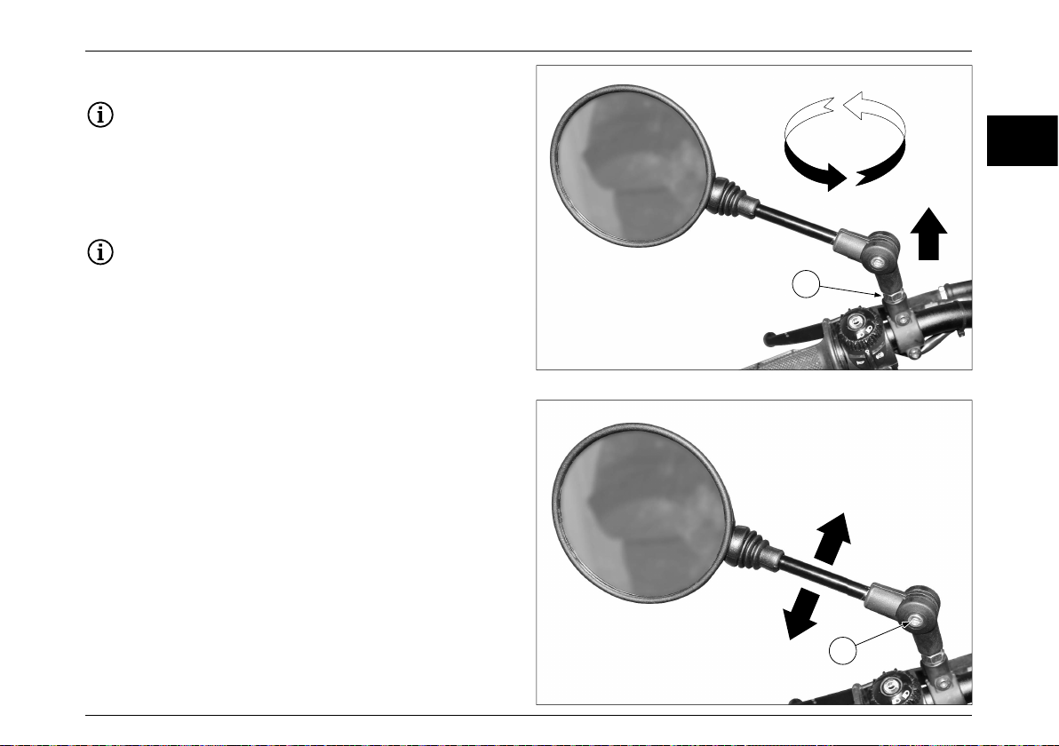
MAINTENANCE
REAR-VIEW MIRRORS
The operations described below apply to both rear-
view mirrors.
Place the vehicle on the kickstand and on a flat and stable
surface. Loosen the lock nut “A”, turn the left-hand mirror
counter-clockwise and remove it, then turn the right-hand
mirror clockwise and remove it.
During reassembly, before tightening the nut, check
that the mirror support rod is aligned with the
handlebar.
Rear-view mirror adjustment
To adjust the rear-view mirrors, get on the vehicle in the
driving position and turn the rear-view mirror according to
your needs. It is also possible to adjust the inclination of the
rear-view mirror support rod. To carry out this operation,
loosen the screw “B” and move the support rod sideways.
Adjust and tighten screw “B”.
IT
EN
DE
A
FR
B
89

MAINTENANCE TABLE
MAINTENANCE TABLE
SCHEDULED MAINTENANCE TABLE
Expert users can normally carry out some maintenance operations even though they require the use of specific equipment
and suitable technical preparation.
If you do not have all the specific tools, suitable clothing and protections, and a suitable place to operate in
complete safety, it is not recommended to perform maintenance operations. If it is necessary to have technical
advice or request service, contact the Authorized Fantic Motor Center.
Fantic Motor declines all civil and criminal liability for damage to the vehicle, property and/or persons due to
maintenance operations performed by the user.
If the user is not interested in performing certain routine maintenance operations, we recommend going to an
Authorized Fantic Motor Service Center.
Carry out maintenance operations more frequently if the vehicle is used in rainy, dusty areas, rough roads or in
the case of fast riding.
Check the engine oil level every 1,000 km (600 mi).
It is essential to make the first inspection and servicing by the end of the first year of use of the vehicle even if
the deadline of 1,000 km (600 mi) has not been reached.
It is essential to make inspection and servicing by the end of the second year of use of the vehicle even if the
specified deadline has not been reached.
The timely execution of the inspection and servicing indicated (the first one in the first year and the second one
in the second year) is necessary for the correct use of the warranty.
Perform the annual checks on a regular basis unless a kilometre (or mileage) interval has expired previously.
90

MAINTENANCE TABLE
Position Operation 1,000 km
Fuel circuit
Spark plug
Valves
Cylinder head
Additional fuel filter
Air filter
Clutch
Front brake
Rear brake
– Check that the fuel pipes are not
cracked or damaged.
– Check its status.
– Clean and restore the electrode
distance.
– Replace.
– Check the valve clearance.
– Adjust.
– Check the cylinder head fastening
bolts tightening.
– Replace.
– Clean.
– Replace.
– Check its operation.
– Adjust.
– Check its operation, the fluid level
and absence of leakage in the
vehicle.
– Replace the brake pads.
– Check its operation, the fluid level
and absence of leakage in the
vehicle.
– Replace the brake pads.
(600 mi)
5,000 km
(3,000 mi)
10,000 km
(6,000 mi)
15,000 km
(9,000 mi)
20,000 km
(12,000 mi)
√√
√√√√√
√
√√√√√
√
Every 10,000 km (6,000 mi).
√√
√√
√√ √
√√ √
If worn up to the limit.
√√ √
If worn up to the limit.
IT
EN
DE
FR
91

MAINTENANCE TABLE
Position Operation 1,000 km
Brake tubes
Brake fluid
Wheels
Tires
Wheel bearings
Swing arm
Transmission chain
– Check for cracks or damage.
– Check that the installation and
tightening are correct.
– Replace.
– Replace.
– Check for misalignment and
damage.
– Check the tread depth and damage.
– Replace if necessary.
– Check the air pressure.
– Correct if necessary.
– Check that the bearings are not
loose or damaged.
– Check its operation and excessive
clearance.
– Lubricate with lithium soap based
grease.
– Check the tension, alignment and
conditions of the drive chain.
– Check the crown and pinion.
– Check the clearance on the rear
sprocket flexible coupling.
– Fully adjust and lubricate the drive
chain with a specific lubricant.
– Replace.
(600 mi)
5,000 km
(3,000 mi)
10,000 km
(6,000 mi)
15,000 km
(9,000 mi)
20,000 km
(12,000 mi)
√√√
Every 4 years.
Every 2 years.
√√
√√
√√
√√
Every 24,000 km (14,000 mi).
Every 500 km (300 mi).
Following heavy use.
If the chain elongation exceeds 2%.
92

MAINTENANCE TABLE
Position Operation 1,000 km
Handlebar bearings
Fixings the frame
parts
Brake lever rotation
pin
Brake pedal rotation
pin
Clutch lever rotation
pin
Side kickstand
Side kickstand switch
Fork
Rear shock absorber
Rear suspension
rotation points
– Check the bearing clearance and
the handlebar hardness.
– Lubricate with lithium soap based
grease.
– Make sure that all nuts, bolts and
screws are properly tightened.
– Lubricate with silicone grease.
– Lubricate with lithium soap based
grease.
– Lubricate with lithium soap based
grease.
– Check its operation.
– Lubricate with lithium soap based
grease.
– Check its operation.
– Check its operation and the absence
of oil leaks.
– Replace oil.
– Check its operation and the absence
of oil leaks in the shock absorber.
– Check the swing arm operation.
– Check the junction arm operation.
(600 mi)
5,000 km
(3,000 mi)
10,000 km
(6,000 mi)
15,000 km
(9,000 mi)
20,000 km
(12,000 mi)
√√ √
Every 24,000 km (14,000 mi).
√√√√√
√√
√√
√√
√√
√√√√√
√√
√√
√√
√√
√
IT
EN
DE
FR
93

MAINTENANCE TABLE
Position Operation 1,000 km
Engine oil
Engine oil filter
Cooling system
Front brake and rear
brake switches
Moving parts and
cables
Throttle control knob
Lights, signals and
switches
– Check the oil level and the absence
of oil leaks in the vehicle.
– Change.
– Replace.
– Check the coolant level and the
absence of oil leaks in the vehicle.
– Coolant change.
– Check its operation.
– Lubricate.
– Check its operation.
– Check the throttle knob grip
clearance and adjust if necessary.
– Lubricate the cable and the knob
body.
– Check its operation.
– Adjust the headlight beam.
(600 mi)
5,000 km
(3,000 mi)
10,000 km
(6,000 mi)
15,000 km
(9,000 mi)
20,000 km
(12,000 mi)
Every 1,000 km (600 mi). √
√√√√√
√√√√√
√√
Every 3 years.
√√ √
√√√√√
√√
√√ √
94

MAINTENANCE TABLE
RECOMMENDED PRODUCTS TABLE
Use lubricating and fluid products that meet the equivalent specifications, or higher than those prescribed.
These same indications are also valid for topping up.
Product Characteristics Remarks
4-stroke gear engine oil
Grease for bearings, joints,
articulations and levers
Coolant
Fork oil Fork oil gradation 15W
Transmission chain lubricant Spray grease for transmission chains
Brake oil Dot 4 or 5.1 brake fluid
Cleaner for electrical contacts Contact cleaner
Fuel 95 or 98 lead-free super petrol
SAE 10W40, API service type SG or greater,
JASO standard MA
Lithium grease
Antifreeze liquid based on ethylene glycol with
organic additives
Do not use mineral oils.
Do not dilute with water.
PETROL FUEL TYPE
E5 E10
IT
EN
DE
FR
Paste for carter and engine covers
coupling
Safety lock medium tightening Medium threadlocker
Three Bond N. 1215®
95

MAINTENANCE TABLE
Product Characteristics Remarks
Safety lock strong tightening Strong threadlocker
Lubricant for bolts unlocking Unblocking protective lubricant
Anti-friction lubricant for screw
tightening torques
Lubricant for rubber oil seals and OR
parts
Battery poles White vaseline grease
Vehicle wash
External cleaning of the brake system
(brake discs and seats)
Low pressure water at room temperature
Generic engine oil
Lithium soap grease
Ecological neutral liquid soap
Spray Disc Brake Cleaner
Avoid aggressive detergents.
Do not use to clean brake
pads and plastic parts.
96


TECHNICAL DATA
TECHNICAL DATA
Maximum length (Scrambler) 2166 mm (85.27 in)
Maximum length (Flat Track) 2180 mm (85.82 in)
Maximum length (Rally) 2190 mm (86.22 in)
Maximum width 820 mm (32.28 in)
Maximum heigth (Scrambler) 1135 mm (44.68 in)
Maximum heigth (Flat Track) 1154 mm (45.43 in)
Maximum heigth (Rally) 1185 mm (46.65 in)
Wheel base (Scrambler) 1423 mm (56.02 in)
Wheel base (Flat Track) 1423 mm (56.02 in)
Wheel base (Rally) 1432 mm (56.38 in)
Weight in running order 160 kg (337.30 lb)
Weight at full load (vehicle, rider, baggage) 330 kg (727.52 lb)
Engine type 4-stroke single cylinder
Number of cylinders 1
Total displacement 448.88 cc (27.39 cu in)
Bore/Stroke 94.5 mm/64 mm (3.72/2.51 in)
Compression ratio 10.8 / 11.5:1
Starting type Electric
N ° of engine revolutions at idle speed 1600 (1 ± 10%) rpm
Lubrication system
Clutch
Technical Data
Multidisk in oil bath
Control on the left side of the handlebar
Casing in oil bath. Pressure system regulated by trochoidal
pump
98

TECHNICAL DATA
Technical Data
Type of cooling Liquid
Coolant 1.5 l (0.32 UK gal, 0.39 US gal)
Type of gearbox
Transmission ratios
(Scrambler)
Transmission ratios
(Flat Track)
Transmission ratios
(Rally)
Pedal control on the left side of the engine
Primary transmission: 64/28 = 2.286
Secondary transmission: 48/13=3.692
Primary transmission: 64/28 = 2.286
Primary transmission: 64/28 = 2.286
Secondary transmission: 48/13=3.692
6-speed mechanical
1st gear ratio: 33/14 = 2.357
2nd gear ratio: 31/17 = 1.824
3rd gear ratio: 28/19 = 1.747
4th gear ratio: 26/22 = 1.182
5th gear ratio: 25/23 = 0.920
6th gear ratio: 21/27 = 0.778
1st gear ratio: 33/14 = 2.357
2nd gear ratio: 31/17 = 1.824
3rd gear ratio: 28/19 = 1.747
4th gear ratio: 26/22 = 1.182
5th gear ratio: 25/23 = 0.920
6th gear ratio: 21/27 = 0.778
Secondary transmission: 52/13=4
1st gear ratio: 33/14 = 2.357
2nd gear ratio: 31/17 = 1.824
3rd gear ratio: 28/19 = 1.747
4th gear ratio: 26/22 = 1.182
5th gear ratio: 25/23 = 0.920
6th gear ratio: 21/27 = 0.778
IT
EN
DE
FR
99

TECHNICAL DATA
Technical Data
Transmission chain
Air filter Paper
Tank capacity (including reserve) 11.5 l (2.52 UK gal, 3.03 US gal)
Capacity of the fuel reserve only 3.5 l (0.76 UK gal, 0.92 US gal)
Quantity (disassembled) 1.6 l (0.35 UK gal, 0.42 US gal)
Engine oil
Seats 2
Maximum allowable weight (rider, passenger, baggage) 177 kg (390.21 lb)
Fuel system
Fuel 95-98 octane super lead-free petrol
Frame
Swing arm (Scrambler) Steel swing arm with variable section
Swing arm (Flat Track) Steel swing arm with variable section
Swing arm (Rally) Variable-section aluminium swingarm made of solid metal
Steering angle (with extended suspensions) 24°
Steering angle (both sides) 39° ± 1°
Front suspension (Scrambler)
Front suspension (Flat Track)
Without oil filter change 0.95 l (0.20 UK gal, 0.25 US gal)
With oil filter change 1 l (0.21 UK gal, 0.26 US gal)
40 mm single-body Athena electronic injection,
singlepoint single injector..
Closed double cradle frame in molybdenum chrome steel
with forged aluminium elements
520 Regina
model 135 ZRA
Upside down fork ø41
Stroke 150 mm (5.90 in)
Upside down fork ø41
Stroke 150 mm (5.90 in)
100
 Loading...