

Page 1

CC
C
U
S
R
Installation Manual
IMPORTANT - PLEASE READ AND SAVE THIS
MANUAL BEFORE INSTALLING UNIT
CAUTION - Before installation, careful consideration must be given to how
this system will operate if connected to any other piece of mechanical equipment, i.e. a forced air furnace or air handler, operating at a higher static. After
installation, the compatibility of the two pieces of equipment must be confirmed by measuring the airflow’s of the Heat Recovery Ventilators.
It is always important to assess how the operation of any HRV may interact
with vented combustion equipment (i.e. Gas Furnaces, Oil Furnaces, Wood
Stoves, etc.).
NEVER - install a ventilator in a situation where its normal operation, lack of
operation or partial failure may result in the backdrafting or improper functioning of vented combustion equipment!!!
Heat Recovery
Ventilators
Your ventilation system should be installed in conformance with the appropriate provincial or state requirements or in the absence of such requirements with local building codes.
Pool and Spa Ventilation Models
SHR 8005R • SHR 14105R
Page 2
Page 3
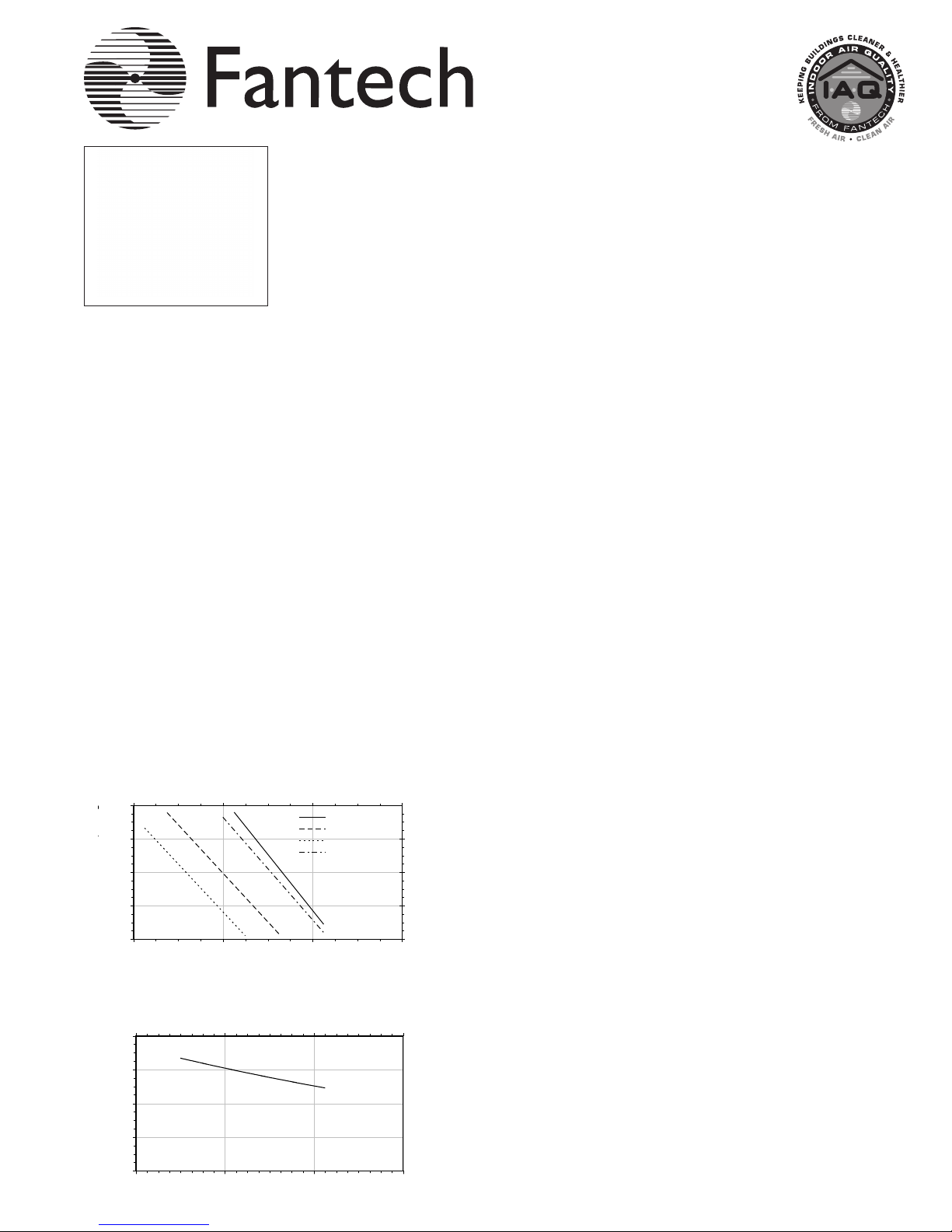
SHR 8005R
0
50
100
150
200
250
275
300
350
400
450
500
550
600
650
700
750
800
850
900
950
2007-10-01
Thermal Effectiveness
10%
30%
50%
70%
90%
0 400 800 1200
Airflow (cfm)
Effectiveness
0 189 378 566
Airflow (l/s)
0
50
100
150
200
250
275
300
350
400
450
500
550
600
650
700
750
800
850
900
950
2007-10-01
Airflow Performance
0.0
0.4
0.8
1.2
1.6
0 400 800 1200
Airflow (cfm)
External Static Pressure, (in wg)
0
99
199
298
0 189 378 566
Airflow (l/s)
External Static Pressure (Pa)
High
Medium
Low
Recirculation
Light Commercial HRV
The Fantech SHR8005R is
designed to provide an economical solution for high humidity
applications such as indoor
swimming pools, spas and fitness facilities. The higher humidity generation rate in these applications leads to annoying window
condensation, mold and structure deterioration. It’s designed to reduce the occurrence of
condensation in the indoor environment by first operating in
recirculation mode, moving air around the structures, sweeping
windows dry and eliminating troublesome cold spots, then
switching to air exchange mode as needed. Air exchange mode
simply exhausts humid air to the outside and replaces it with
drier air from outside. The airstreams are separated by an
energy efficient heat recovery core which uses the energy in the
exhaust air to lower the load on the HVAC system. Automatic
defrost and provisions for condensation are standard.
APPLICATIONS INCLUDE:
• Indoor Pools • Night Clubs
• Spa's • Locker Room
• Health Centers • High humidity Applications
POWER & WEIGHT
• Volts 120V
• Amperage 5.4 Amps Total
• Weight 80.3 Kg (177 Lbs)
• Shipping Weight 98 Kg (217 Lbs)
• Blowers (x2) 115V, 60 Hz, 2.7 Amps
• Phase Single
Airflow Performance
Airflow (l/s)
External Static Pressure, (in wg)
Airflow (cfm)
Thermal Effectiveness
Airflow (l/s)
External Static Pressure (Pa)
SPECIFICATIONS
CASE 20 gauge G90 galvanized steel coated with baked
powder paint, insulated with 25mm (1 inch) and 50mm (2
inch) on outdoor air side foil-faced high density polystyrene
foam for condensation control.
BLOWERS Two (2) maintenance-free Ebm-Papst™ backward
inclined motorized impellers with permanently lubricated sealed
ball bearings and (TOP) thermal overload protected.
HEAT RECOVERY CORES The heat recovery cores are fixed plate
cross-flow heat exchanger using 1100 alloy aluminum and
capable of transferring sensible heat between air streams.
The heat recovery cor
inducing geometry in order to maximize heat transfer while
allowing an effective evacuation of condensate. The plates are
hemmed to avoid cross-contamination of airstreams.
FILTERS The exhaust and fresh air streams are protected by
MERV1 washable filters constructed to meet UL Class2.
Optional MERV6 filters are direct replacement to the MERV1.
Use of MERV6 filters will add an additional system pressure
of 72 Pa (0.29in.wg) at 378 l/s (800cfm).
MOUNTING Unit can be rod mounted or seated on a
platform. Flanged connections are provided for suitable
ductwork connections. Unit shall be adaptable for easy
service of electrical components.
CONTROLS External three (3) position (Low/Standby/Medium)
rocker switch that will offer continuous ventilation. Compatible
with all Fantech HRV controls.
FROST CONTROL During the defrost sequence, a motorized
damper temporarily blocks the incoming fresh air stream so
that the warm air from the building can circulate thr
HRV. The exhaust blower shuts down and the supply blower
switches into high speed to maximize the effectiveness of the
defrost strategy.
SERVICEABILITY Unit has hinged or screwed access panels on
front and back. Cores, filters, motors and drain pan are
serviceable from either sides of the unit. Fan assemblies are
mounted on a removable sliding base. Heat recovery cor
mounted in slide-out rails for ease of inspection, removal and
cleaning. Accessibility to the electrical box is maintained for
any unit installation.
es are engineered with a turbulence
ough the
es are
Effectiveness
Airflow (cfm)
3
Page 4
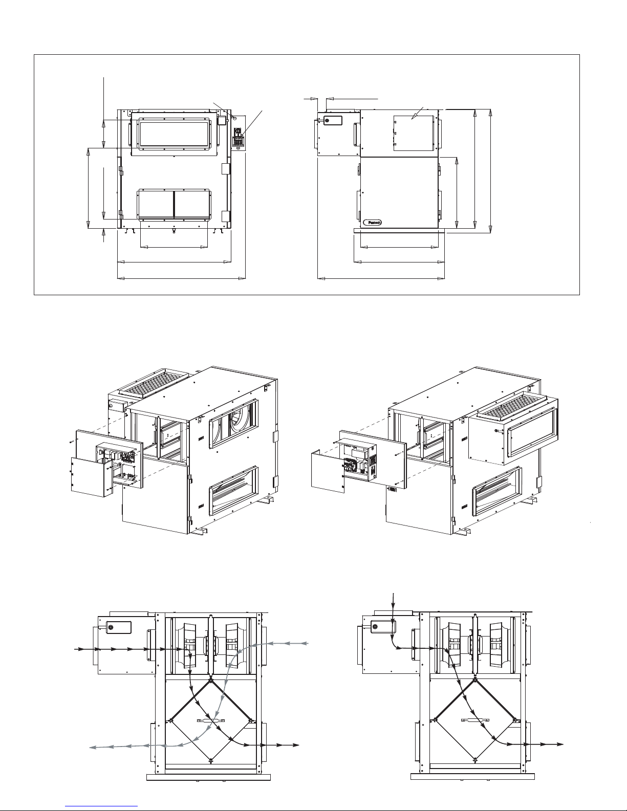
SHR 8005R Light Commercial HRV
9
24mm(36.4")
203mm(8")
576mm(22.7")
66mm(2.6")
818mm(32.2")
5
08mm(20")
653mm(25.7")
559mm(22")
9
14mm(36")
888mm(35")
855mm(33.7")
ELECTRIC BOX (can be relocated in the field
to either the front or the back of the cabinet)
LOW VOLTAGE
C
ONTROL PANEL
HIGH VOLTAGE
ENTRY
63mm(2.5")
513mm(20.2")
Outdoor or Recirculated Air
Indoor Air
Standard Configuration as shipped from factory.
Outdoor or Recirculated Air
Indoor Air
Dimensions
PORT CONFIGURATION
The unit has access doors on the front and back. Also, the main control panel may be moved from front to back
allowing for ducting layout.
Outdoor or
Recirculated
Airflow
Fresh Air
from Outside
Air
Indoor
Air
Factory Setting. Unit may be easily
reversed in field.
Stale Air
from Inside
Indoor
Air
Recirculated Air
from Building
Outdoor or
Recirculated
Air
Stale Air
4
to Outside
Fresh Air
to Inside
Recirculated
Air to Inside
Page 5
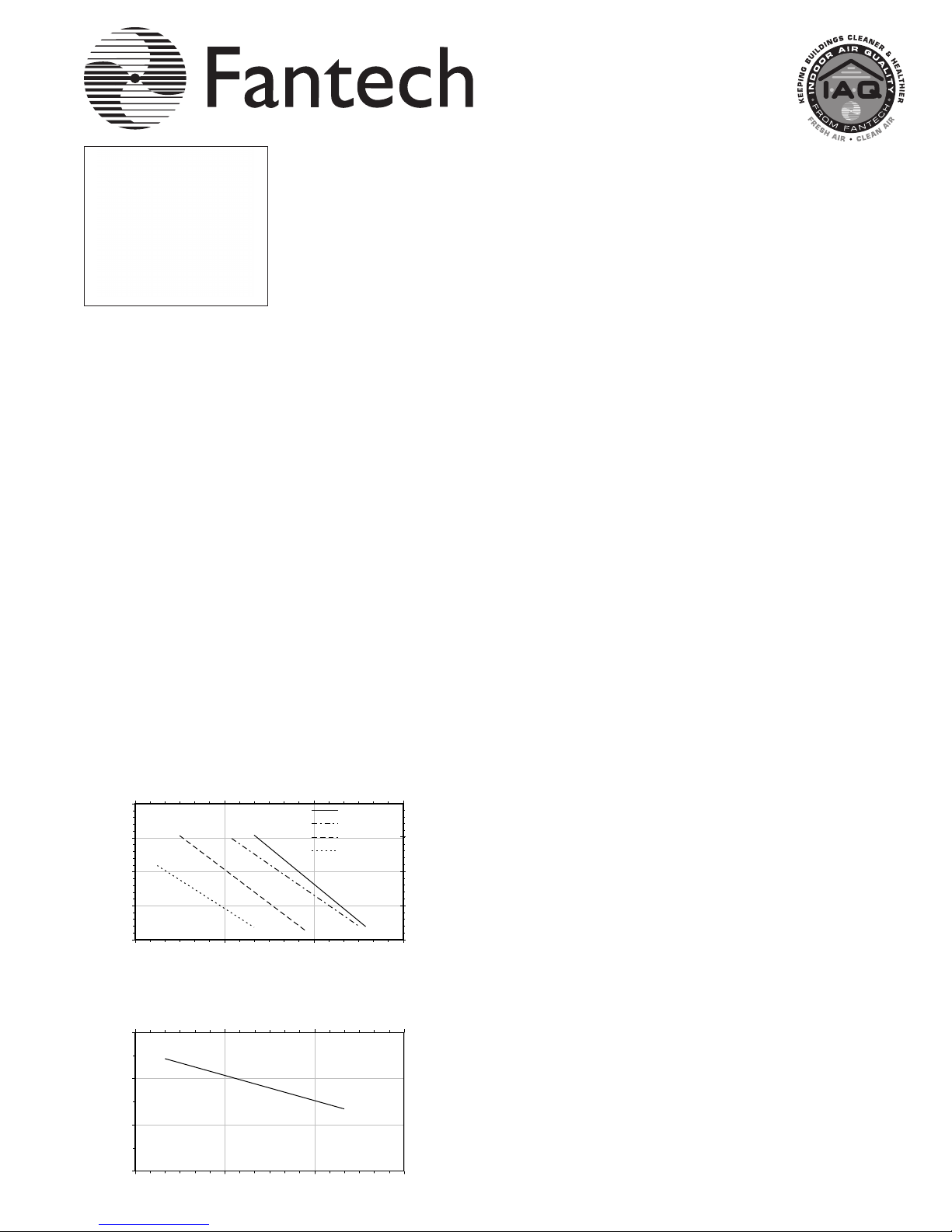
SHR 14105R
0
50
100
150
200
250
275
300
350
400
450
500
550
600
650
700
750
800
850
900
950
1000
1050
1100
1150
1200
1250
1300
1350
1400
1450
1500
1550
0.0
0.4
0.8
1.2
1.6
0 600 1200 1800
0
99
199
298
398
0 283 566 849
Airflow Performance
0.0
0.5
1.0
1.5
2.0
0 600 1200 1800
Airflow (cfm)
External Static Pressure, (in wg)
0
125
251
376
0 283 566 849
Airflow (l/s)
External Static Pressure (Pa)
High
Recirculation
Medium
Low
0
50
100
150
200
250
275
300
350
400
450
500
550
600
650
700
750
800
850
900
950
1000
1050
1100
1150
1200
1250
1300
1350
1400
1450
1500
1550
2007-10-01
200
1400
Termal Effectiveness
30%
50%
70%
90%
0 600 1200 1800
Airflow (cfm)
Effectiveness
0 283 566 849
Airflow (l/s)
Light Commercial HRV
The Fantech SHR14105R is
designed to provide an economical solution for high humidity
applications such as indoor
swimming pools, spas and fitness facilities. The higher humidity generation rate in these applications leads to annoying window
condensation, mold and structure deterioration. It’s designed to reduce the occurrence of
condensation in the indoor environment by first operating in
recirculation mode, moving air around the structures, sweeping
windows dry and eliminating troublesome cold spots, then
switching to air exchange mode as needed. Air exchange mode
simply exhausts humid air to the outside and replaces it with
drier air from outside. The airstreams are separated by an
energy efficient heat recovery core which uses the energy in the
exhaust air to lower the load on the HVAC system. Automatic
defrost and provisions for condensation are standard.
APPLICATIONS INCLUDE:
• Indoor Pools • Night Clubs
• Spa's • Locker Room
• Health Centers • High humidity Applications
POWER & WEIGHT
• Volts 120V
• Amperage 10.6 Amps Total
• Weight 116 Kg (255 Lbs)
• Shipping Weight 134 Kg (295 Lbs)
• Blowers (x4) 115V, 60 Hz, 2.7 Amps
• Phase Single
Airflow Performance
Airflow (l/s)
External Static Pressure, (in wg)
Effectiveness
Airflow (cfm)
Thermal Effectiveness
Airflow (l/s)
SPECIFICATIONS
CASE 20 gauge G90 galvanized steel coated with baked
powder paint, insulated with 25mm (1 inch) and 50mm (2
inch) on outdoor air side foil-faced high density polystyrene
foam for condensation control.
BLOWERS Four (4) maintenance-free Ebm-Papst™ backward
inclined motorized impellers with permanently lubricated sealed
ball bearings and (TOP) thermal overload protected.
HEAT RECOVERY CORE The Heat recovery Cores are fixed plate
cross-flow heat exchanger using 1100 alloy aluminum and
capable of transferring sensible heat between air streams.
The heat recovery cor
inducing geometry in order to maximize heat transfer while
allowing an effective evacuation of condensate. The plates are
hemmed to avoid cross-contamination of airstreams.
FILTERS The exhaust and fresh air streams are protected by
MERV1 washable filters constructed to meet UL Class2.
Optional MERV6 filters are direct replacement to the MERV1.
Use of MERV6 filters will add an additional system pressure
of 90 Pa (0.36in.wg) at 665 l/s (1410cfm).
MOUNTING Unit can be rod mounted or seated on a
platform. Flanged connections are provided for suitable
ductwork connections. Unit shall be adaptable for easy
service of electrical components.
CONTROLS External three (3) position (Low/Standby/Medium)
rocker switch that will offer continuous ventilation. Compatible
with all Fantech HRV/ERV controls.
FROST CONTROL During the defrost sequence, a motorized
damper temporarily blocks the incoming fresh air stream so
that the warm air from the building can circulate thr
HRV. The exhaust blower shuts down and the supply blower
switches into high speed to maximize the effectiveness of the
defrost strategy.
SERVICEABILITY Unit has hinged or screwed access panels on
front and back. Cores, filters, motors and drain pan are
serviceable from either sides of the unit. Fan assemblies are
External Static Pressure (Pa)
mounted on a removable sliding base. Heat recovery cor
mounted in slide-out rails for ease of inspection, removal and
cleaning. Accessibility to the electrical box is maintained for
any unit installation.
es are engineered with a turbulence
ough the
es are
Airflow (cfm)
5
Page 6
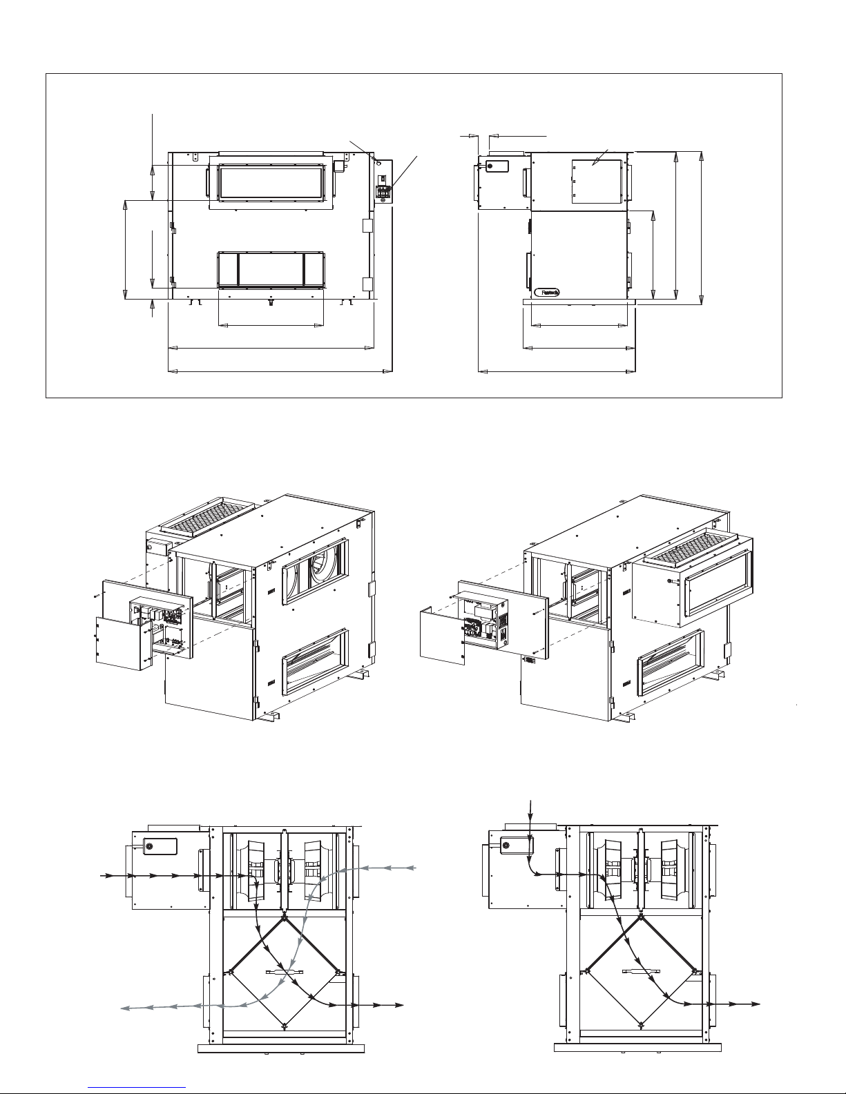
SHR 14105R Light Commercial HRV
914mm(36")
559mm(22")
1199mm(47.2")
1305mm(51.4")
203mm(8")
66mm(2.6")
576mm(22.7")
610mm(24")
653mm(25.7")
855mm(33.7")
888mm(35")
513mm(20.2")
H
IGH VOLTAGE
ENTRY
LOW VOLTAGE
CONTROL PANEL
E
LECTRIC BOX (can be relocated in the field
to either the front or the back of the cabinet)
63mm(2.5")
Outdoor or Recirculated Air
Indoor Air
Standard Configuration as shipped from factory.
Outdoor or Recirculated Air
Indoor Air
Dimensions
PORT CONFIGURATION
The unit has access doors on the front and back. Also, the main control panel may be moved from front to back
allowing for ducting layout.
Outdoor or
Recirculated
Airflow
Fresh Air
from Outside
Air
Indoor
Air
Factory Setting. Unit may be easily
reversed in field
Stale Air
from Inside
Indoor
Air
Recirculated Air
from Building
Outdoor or
Recirculated
Air
Stale Air
6
to Outside
Fresh Air
to Inside
Recirculated
Air to Inside
Page 7

MODES OF OPERATION
1. Continuous / Ventilation Mode
In this mode of operation, both fans are operating and exchanging air with the outside. The heat recovery ventilator (HRV) constantly
exchanges the air at the rate you select, either at low or medium speed, and switches to high speed when activated by an optional
remote control. Continuous mode is recommended, since pollutants are slowly but constantly being generated in a building.
2. Recirculation Mode
In recirculation mode, the supply motor continues to run and a damper moves to block off air entering from outside, drawing air instead
from the conditioned space. The exhaust to outside motor is OFF when in recir
culation mode.
3. Intermittent / Standby Mode
The system is always on standby and operates at high speed when activated by an optional remote control (required): "Standby"
should be selected if the user wishes to stop the unit from continuous exchange.
4. Defrost
A preset defrost sequence is activated at an outdoor air temperature of -5ºC (23ºF) and lower.
During the defrost sequence, the motorized damper in the bypass module (BPM) temporarily blocks the incoming fresh air stream so
that the warm air from the room can circulate through the HRV. The exhaust blower shuts down and the supply blower switches into
high speed to maximize the effectiveness of the defrost strategy. During this cycle, the unit will not create a negative pressure. Please
note that these systems are configured to defrost with the BPM devices installed on the fresh air from outside port. Alternate configuration are available by contacting our technical support department.
SETTING SPEED
Intermittent operation can be obtained by toggling the switch located on outside of cabinet. External low voltage contacts allow for
high speed operation when an optional remote control is used.
Convenient Optional Low Voltage Wall Controls
Main Control
EDF1R
Triple Function Wall Control
The EDF1R is designed to provide 3 modes of operation to the
Heat/Energy Recovery Ventilator.
• Pressing the “Fan” button
once initiates the unit to run
at a continuous low speed of
operation (green).
2-wire
Boost Switches
RTS 2
Pushbutton Timer
• 20-Minute Timer with LED
• Boosts system to high
• Up to five can be used
2-wire 3-wire
• Use in bathrooms,
• Pressing the button twice
allows the HRV/ERV to run
continuous cycle of 20 minutes on and then standby for
40 minutes.
• Touch the button a third time
and the system will run recirculation at high speed (red).
The ventilation system will stay
on the last function selected
until it is manually changed.
Light
speed with the touch
of a button
with one system
kitchens, laundry
RTS3
Pushbutton Timer
• 20-40-60 Min. Boost Timer
• Press button once to energize
system to high speed for 20
minutes
• Press button twice unit unit
will run for 40 minutes on
high speed.
• Press button three times for
60 minutes of high speed
• Up to five can be used with
one system
EDF5
Five-Function Wall Control
• Features: Digital Display,
Maintenance Light, Power
Button, Cycle Timer,
Longer Override Timer,
Speed Control and
Dehumidistat Control.
• Intermittent, Recirculation or
2-wire
Continuous Ventilation Modes
• Use in one central location
MDEH1
Dehumidistat
2-wire
• Rotary Dial Dehumidistat
• Just turn dial to set desired
humidity level
• Multiple units can be used
• Install in bathrooms,
kitchen, laundry
• Dehumidifies when air outside is dryer than air inside
7
Page 8
INSTALLATION
A
B
F
E
D
C
G
LOCATION
The HRV must be located in a conditioned space where it will be possible to conveniently service the unit. Typically the HRV would be
located in the mechanical room, above a drop ceiling or an area close to the outside wall where the weatherhoods will be mounted.
Attic installations are not recommended due to extreme temperatures, and difficulty in performing, required service & maintenance.
Care must be taken to locate the recirculation port in an area that will not cause any unwanted contaminant to be drawn into the living space during recirculation and defrost.
Connecting appliances to the HRV It is not recommended, including:
- clothes dryer
- kitchen exhaust hoods
- combustion venting
TIP: Flexible duct connectors should be
installed between the HRV and the galvanized ductwork.
- central vacuum system
These appliance may cause lint, dust or grease to collect in the HRV , damaging the unit.
NOTE: Connecting any of these type of appliances to the HRV will invalidate your warranty
Model A B C D E F G
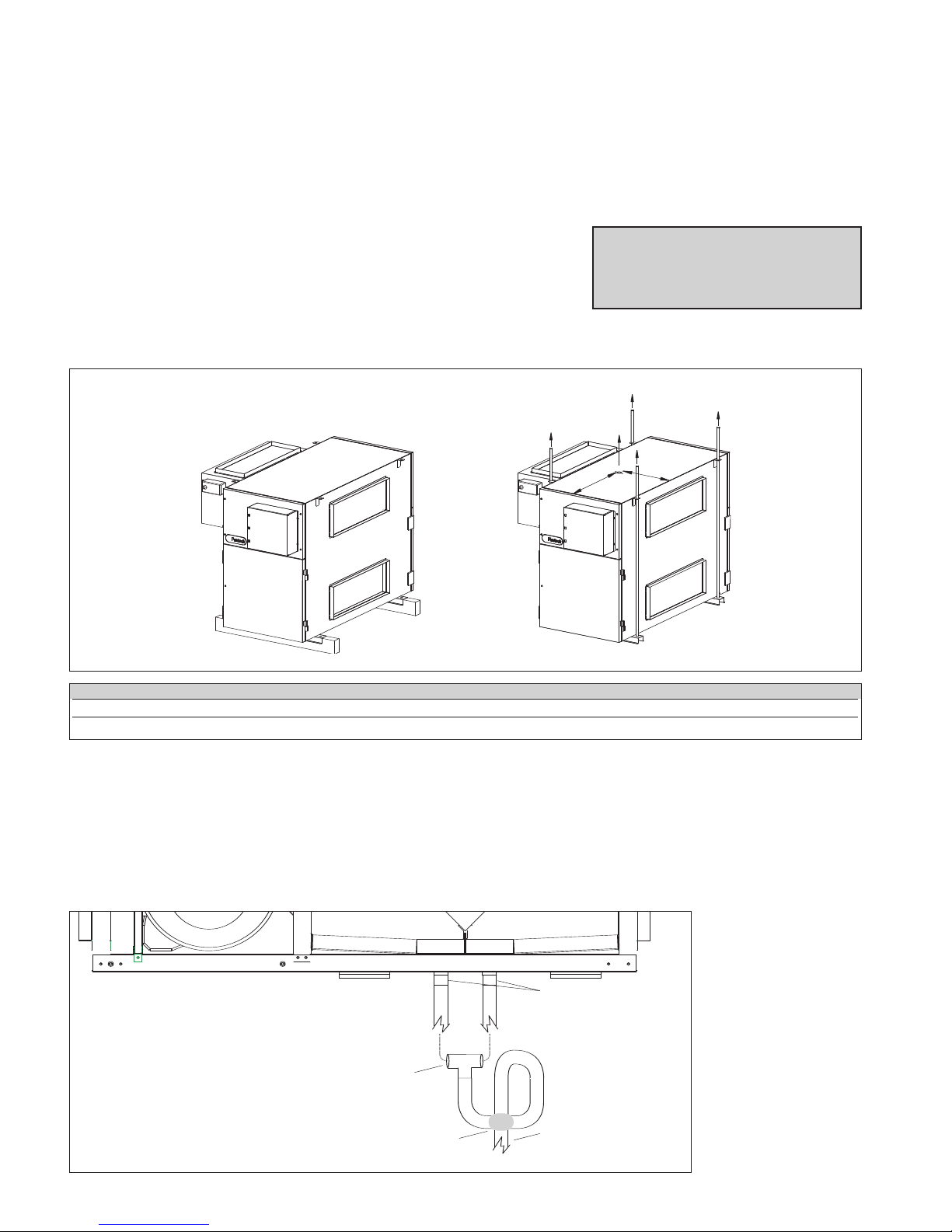
SHR 8005R 23.8Kg (52.5lbs) 22.5Kg (49.6lbs) 390mm (15.4") 85Kg (187lbs) 20Kg (44lbs) 18.8Kg(41.3lbs) 448mm (17.6")
SHR 14105R 30.4Kg (67lbs) 27Kg (60lbs) 544mm (21.4") 109Kg (241lbs) 27.7Kg (61lbs) 24.3Kg (53.5lbs) 455mm (18")
Installing Drain Line
Through normal operation and including defrost mode, the HRV may produce some condensation. This water should flow into a nearby
drain, or be taken away by a condensate pump. The HRV and all condensate lines must be installed in a space where the temperature is maintained above freezing point. A “P” trap should be made in the drain line. This will prevent odors fr
om being drawn back
up into the unit.
Install the drain hose, making a “P” trap
Tee
Drain
Spout
Connector
Tape
or Tie Wrap
The water should be
drained back into the
pool and not wasted
8
Page 9

INSTALLING DUCTS GOING TO / FROM OUTSIDE
INSTALLING THE DUCTING TO THE WEATHERHOODS
OUTSIDE WEATHERHOODS –
prevent birds and rodents from entering into the ductwork. Do not use smaller mesh as it will be very susceptible to plugging up.
The preferred location of the weatherhoods is:
• No less than 3 m (10 ft.) apart from each other.
• At least 457.2 mm (18 inches) snow line or ground level.
• Supply hood must be kept away from sources of contaminant, such as automobile exhaust fumes, gas meters, garbage
cans, containers, cooling towers, tar roofs, etc.
• Avoid prevailing winds, whenever reasonably possible.
The outside perimeter of the weatherhood must be sealed to prevent leakage into the building.
The weatherhoods must have built-in "bird" screens with 6.35 mm (1/4 inch) minimum mesh to
DUCTING FROM THE WEATHERHOODS–TO AND FROM THE HRV – Galvanized sheet metal ducting with sufficient cross sec-
tion with an integral single piece of insulated wrap with vapor barrier should be used to connect the HRV to the weatherhoods. The
R-value of the insulation should be adequate for condensation control. Insulated flex duct may be used in moderation, if sized and
installed properly. (Consult local codes)
All ducts should be sealed using a good bead of high quality caulking (preferably acoustical sealant) and a high quality aluminum foil
tape, or other approved duct sealant.
INSTALLING DUCTS TO / FROM INSIDE
To maximize airflow in the ductwork system, all ducts should be kept short and have as few bends or elbows as possible. Fortyfive degree are preferred to 90˚ elbows. Use “Y” tees instead of 90˚ elbows whenever possible.
All duct joints must be fastened with screws or duct sealant and wrapped with a quality duct tape to prevent leakage. Aluminum
foil duct tape is recommended.
SUPPLY AIR DUCTING
In buildings without a forced air HVAC systems, fresh air should be supplied to all habitable areas. It should be supplied from
high wall or ceiling locations. The grilles that are to be used should be designed to properly and comfortably sweep cold surfaces.
Optional inline duct heaters may be used to add heat if required. Typically the reheat is best done using a coil off the same boiler that
heats the pool water.
Direct Connection to Furnace/ Air handler return duct
• Should you wish to hard duct the supply air directly into the cold air return of the HVAC systems, remember to check the airflow balance of the HRV with the HVAC systems fan both “on”and “off” to determine that it does not imbalance the HRV more than 10%.
Make sure you respect the minimum distance from the supply air in of the HRV and the HVAC systems.
• It may be necessary to install a separate fresh air supply ductwork system if the heating is other than forced air.
When installing an HRV, the designer and installer should be aware of local codes that may require smoke detectors and/or
firestats in the HVAC or HRV ductwork.
Because an HRV is designed to bring fresh air into the building, structures may require supply voltage interrupt when smoke or
flame sensors are triggered, or when a central fire alarm system is activated.
Exhaust Air ducting
The stale air exhaust system is used to draw air from the points in the building where the worst air quality problems occur. ( See
installation examples in the manual.)
9
Page 10
Magnehelic
Magnehelic
Gauge
D
uct
Air
Flow
Pito t
Tub e
AIR FLOW BALANCING
INTERIOR WALL
EXTERIOR WALL
EXTERIOR WALL
POOL HRV
MECHANICAL ROOM
E
XTERIOR WALL
RECIRCULATION
BACKDRAFT DAMPER
MDH1 Control
EDF1R Control
INTERIOR WALL
EXTERIOR WALL
EXTERIOR WALL
POOL HRV
EXTERIOR WALL
RECIRCULATION
BACKDRAFT DAMPER
RETURN
GRILL
MDH1 Control
EDF1R Control
MECHANICAL ROOM
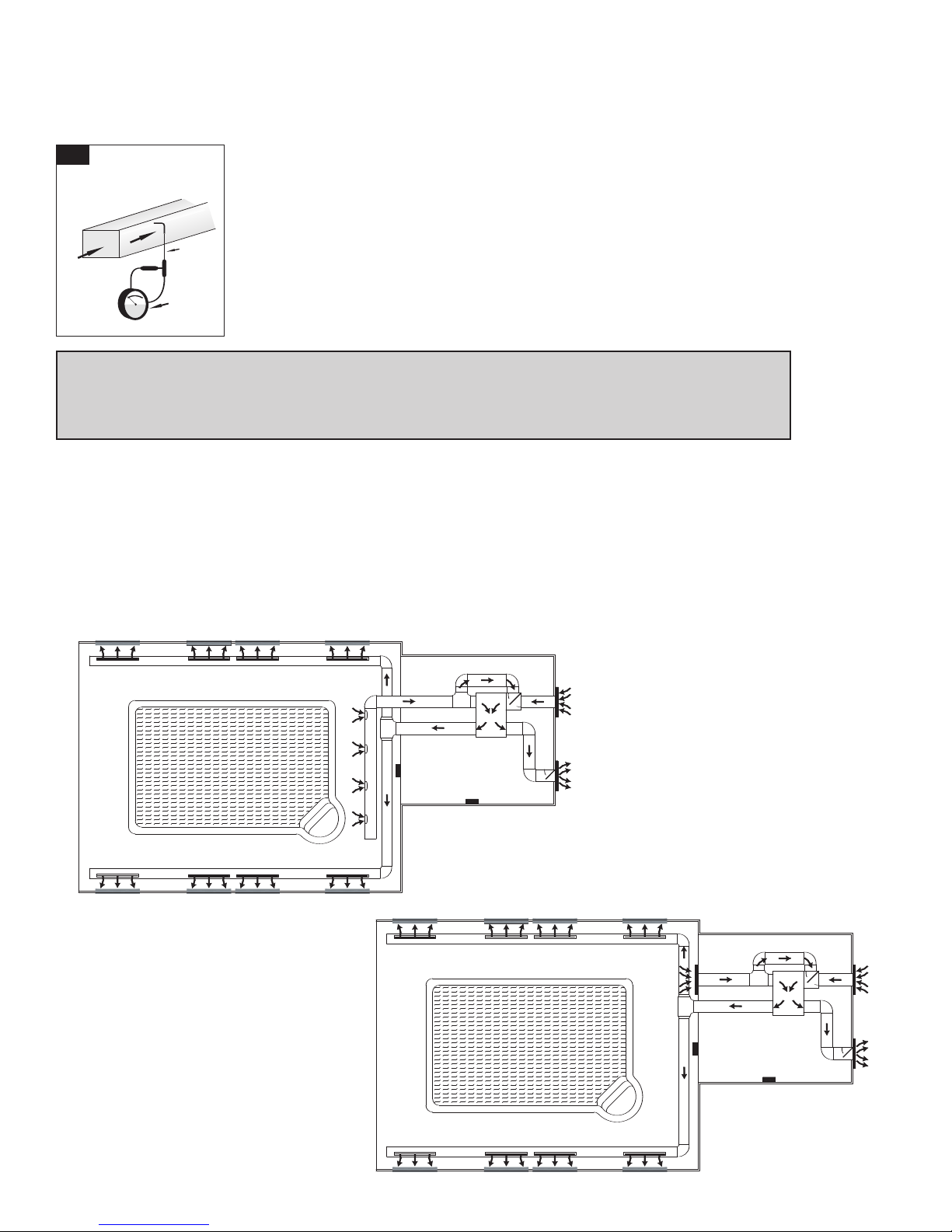
• The balancing procedure consists of measuring the exhaust air leaving the system and the supply air entering the system and
ensuring that these two are equal. A deviation of 10% or less is acceptable.
A*
Pitot tube and gauge
A The duct’s airflow veloc-
ity is generally measured with a magnehelic
gauge and a pitot tube.
• To avoid airflow turbulence and incorrect
readings, the airflow
velocity should be measured on steel ducting a
minimum of 3 duct
cross-section from the
unit or elbow and before
any transition.
Note: A professional air balancer should be contacted to commission the system properly.
A skilled HVAC Tech may complete the balance of air providing they possess the proper
equipment. Call Fantech Technical support for assistance.
INSTALLING BYPASS MODULE (BPM)
REFER TO BPM INSTALLATION, OPERATION AND MAINTENANCE
DOCUMENT FOR INSTRUCTIONS
INSTALLATION EXAMPLES
Installation with Grille
10
Page 11
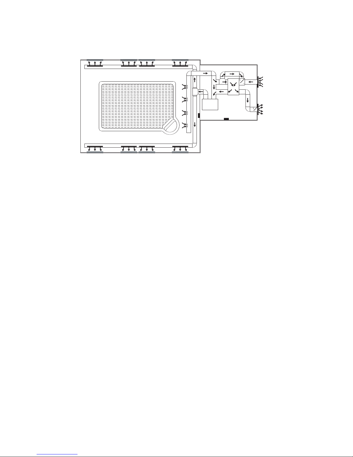
INSTALLATION EXAMPLES CON'T
INTERIOR WALL
E
XTERIOR WALL
EXTERIOR WALL
P
OOL HRV
EXTERIOR WALL
AIR HANDLER
RECIRCULATION
B
ACKDRAFT DAMPER
M
DH1 Control
E
DF1R Control
MECHANICAL ROOM
HVAC
MAINTENANCE
CAUTION MAKE SURE UNIT IS UNPLUGGED BEFORE ATTEMPTING ANY MAINTENANCE WORK
The following components should also be inspected regularly and well maintained.
The motor - The motors are
factory balanced and lubricated for life. They require no
maintenance.
The unit - The inside of the
unit should be wiped clean
as needed.
Condensation Pan - Units
with drain hoses should have
their line and connection
checked regularly.
Outside hoods - The outside
hoods need to be checked
every season to make sure
there are no leaves or insects
blocking the airflow. Check
regularly that there are no pollutants near the intake hood.
Make sure they are clear of
any snow accumulation during
the winter months.
FILTERS
The filters need to be checked and cleaned once a month or when they appear dirty.
FIXED PLATE
Clean cores on a average every 3-6 months or as needed.
a) Open access door & remove filters.
b)
c) Wash the cores in warm soapy water or light coil
d) Install clean cores making sure the matting sur-
e) Install the clean filters
f) Replace access door
Note: Core installation label on the outer end of the core.
To install the clean Core and Filters.
a) First mount the bottom flange of the core guide into the
b
c) Mount the top flange of the core guide into the top
d) With all four corners in place and the core straight and
Carefully pull on handle of core and pull evenly outward.
Cores may be snug, but will slide out of the channel.
solution.
faces have one sealing edges between each cores
to minimize leaks.
bottom channel approximately 6mm (1/4")
) Mount the left or right side flange of the core guide
approximately 6mm (1/4") followed by the other side
channel approximately 6mm (1/4")
even, push hard in the centre of the core until the
core stops on the back of the cabinet.
11
Page 12
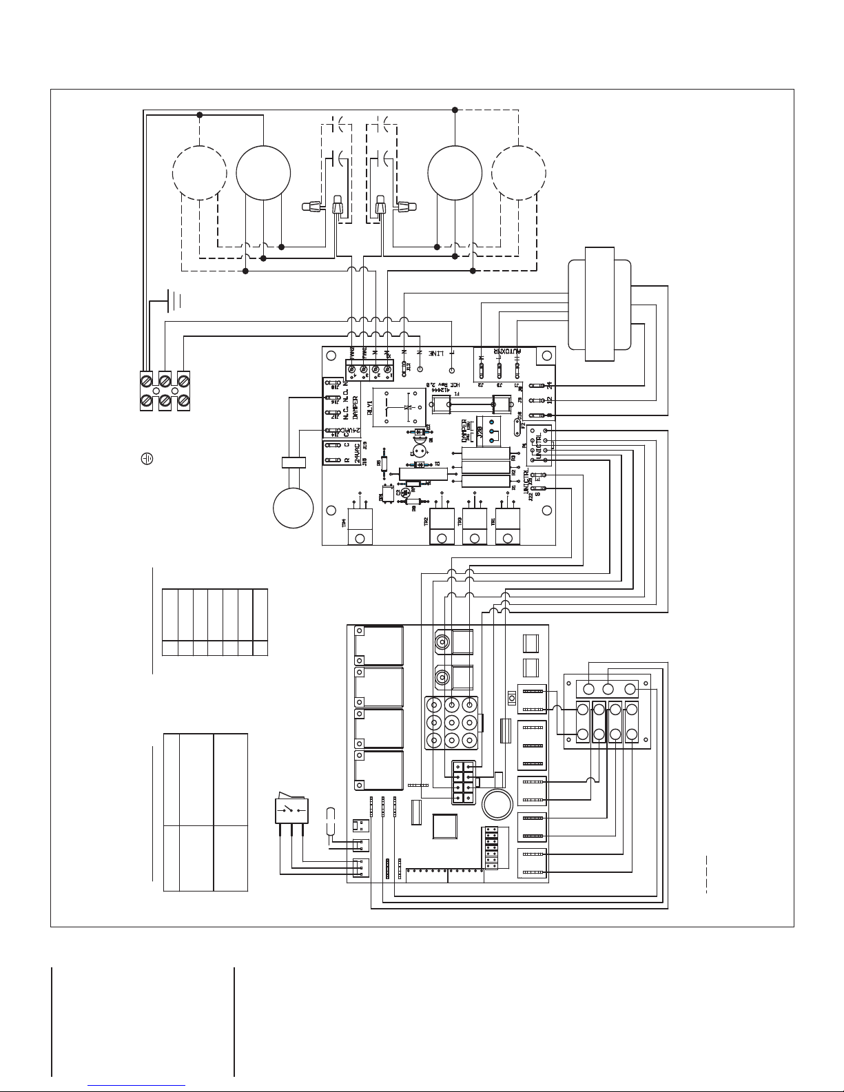
WIRING DIAGRAM SHR 8005R AND SHR 14105R
DASHED LINES INDICATED ADDITIONAL COMPONENTS FOUND IN MODEL TYPES FAH1200 & FAH1400
WHT/YELLOW
WHT/GREEN
YELLOW
WHT/BLUE
GREEN
BLUE
RED
BLUE
BLUE
BROWN
BLACK
BROWN
BLACK
EXH2
GREEN
EXH1
GREEN
CAP1BCAP1A
GREEN
BLACK
RED
STAND BY
T.P
SW1
LOW
MED
BLACK
BROWN
BLUE
BROWN
BLACK
BLUE
CAP2BCAP2A
SUP1
GREEN
SUP2
GREEN
D.M
Supply Voltage
8 AMPS, 250V, 3AB or
3AG FAST ACTING
12 AMPS, 250V, 3AB or
3AG FAST ACTING
GREEN
COM
CUR SW
IN
DEHUM
TIMER
+
+ -
-
N.C.
COM
N.O.
FURNACE
INTERLOCK
EDF
+ -
BLUE
BLACK
RED
GREEN
GREEN
YELLOW
MCI-7018/7030
YELLOW
GREEN
GREEN
BLACK
RED
BLACK
RED
BLUE
BLACK
RED
WHITE
BLACK
WHITE
UNI-CTRL
JUMPER SETTINGS
OFF
ON
ON
OFF
ON
OFF
ON
J4J6J5
J7
J1J2J3
(GROUND)
N (WHITE)
L (BLACK)
FUSE SPECIFICATION
FAH0800
HCE PCB REPLACEMENT
FAH0900
FAH1400
FAH1200
TYPE FUSE RATING
PROGRAMEXP
COM
N.O.
N.C.
AUX
J7
CUR SW DEHUM TIMER AQS WALL
PWR
N
.O.
C
OM
J6 J5
DEFROST
J4
J3 J2 J1
United States
1712 Northgate Blvd.,
Sarasota, FL. 34234
Phone: 800.747.1762; 941.309.6000
Fax: 800.487.9915; 941.309.6099
www.fantech.net; [email protected]
Canada
50 Kanalflakt Way,
Bouctouche, NB E4S 3M5
Phone: 800.565.3548; 506.743.9500
Fax: 877.747.8116; 506.743.9600
www.fantech.ca; [email protected]
Fantech, reserves the right to modify, at any time and without notice,
any or all of its products’ features, designs, components and specifications to maintain their technological leadership position.
Item #: 404126
Rev Date:122107
 Loading...