

Page 1

VER150
Energy Recovery Ventilator
Item #: 422728
Rev Date: 2017-11-07
Installation Manual
Your ventilation system should be installed in conformance with the appropriate provincial/state requirements or, in the
absence of such requirements, with the current edition of the National Building Code, and / or ASHRAE’s “Good Engineering
Practices”.
United States
10048 Industrial Blvd., Lenexa, KS, 66215
Tel.: 800.747.1762 • Fax: 800.487.9915
Canada
50 Kanalflakt Way, Bouctouche, NB, E4S 3M5
Tel.: 800.565.3548 • Fax: 877.747.8116
Fantech reserves the right to modify, at any time and without notice, any or all of its products’ features, designs,
components and specifications to maintain their technological leadership position.
Please visit our website www.fantech.net for more detailed technical information.
Page 2

2
Note Warning/
Important
Information Technical
information
Practical tip
note
PLEASE READ THIS MANUAL BEFORE INSTALLING UNIT
Before installation careful consideration must be given to how this system will operate if connected to
any other piece of mechanical equipment, i.e. a forced air furnace or air handler operating at a higher
static pressure. After installation, the compatibility of the two pieces of equipment must be conrmed by
measuring the airow of the Energy Recovery Ventilator using the balancing procedure found in this manual.
It is always important to assess how the operation of any ERV may interact with vented combustion equipment (i.e.
Gas Furnaces, Oil Furnaces, Wood Stoves, etc.)
Products are designed and manufactured to provide reliable performance, but they are not guaranteed to be 100%
free of defects. Even reliable products will experience occasional failures, and this possibility should be recognized
by the user. If these products are used in a life support ventilation system where failure could result in loss or injury,
the user should provide adequate back-up ventilation, supplementary natural ventilation or failure alarm system, or
acknowledge willingness to accept the risk of such loss or injury.
Your ventilation system should be installed in accordance with the local building code that is in effect, in absence
of such requirements, it is recommenced to check with local authorities having jurisdiction in your area prior to
installing this product.
fantech
Page 3

TABLE OF CONTENTS
DETERMINING YOUR AIRFLOW REQUIREMENT ..................................................... 4
INSTALLATION EXAMPLES
Fully dedicated system ................................................................ 5
Partially dedicated system .............................................................. 6
Simplified Installation
Option 1 ...................................................................... 7
Option 2 .......................................................................8
EXTERIOR DUCTING INSTALLATION
Weatherhood Location ................................................................. 9
Installing the ducting to the weatherhood ................................................... 9
INTERIOR DUCTING INSTALLATION
General Tips ....................................................................... 10
Installing duct to ERV ................................................................ 10
Supply & Exhaust Air Grilles Location...................................................... 10
3
ERV INSTALLATION ......................................................................... 11
AIRFLOW ADJUSTMENT & BALANCING
General preparation ................................................................. 13
Adjusting airflow using integrated balancing system ........................................... 13
Balancing steps .................................................................... 14
LOW VOLTAGE CONTROL SYSTEMS ............................................................. 15
WIRING DIAGRAM ......................................................................... 16
TROUBLESHOOTING .........................................................................18
ERV MAINTENANCE CHART....................................................................19
ERV CORE WASHING INSTRUCTIONS ............................................................20
PARTS LIST ...............................................................................21
fantech
Page 4

4
DETERMINING YOUR AIRFLOW REQUIREMENT
Room Count Method
1 CFM = 0.47 L/s
1 L/s = 2.13 CFM
ASHRAE method
Room classification Number of rooms CFM (L/s)
Master bedroom x 10 L/s (20 CFM) =
Basement yes or no =
Bedrooms x 5 L/s (10 CFM) =
Living room x 5 L/s (10 CFM) =
Others x 5 L/s (10 CFM) =
Kitchen x 5 L/s (10 CFM) =
Bathroom x 5 L/s (10 CFM) =
Laundry room x 5 L/s (10 CFM) =
Utility room x 5 L/s (10 CFM) =
Total Ventilation Requirements (add last column ) =
if yes add 10 L/s (20 CFM)
if no = 0
CFM Required
Ventilation Air requirements
Floor area Bedrooms
0-1 2-3 4-5 6-7 >7
2
Ft
< 1500 <139 30 14 45 21 60 28 75 35 90 42
1501-3000 139.1-279 45 21 60 28 75 35 90 42 105 50
3001-4500 279.1-418 60 28 75 35 90 45 105 50 120 57
4501-6000 418.1-557 75 35 90 42 105 50 120 57 135 64
6001-7500 557.1-697 90 42 105 50 120 57 135 64 150 71
>7500 >697 105 50 120 57 135 64 150 71 165 78
* ASHRAE 62.2-2010 Table 4.1, Ventilation and Acceptable Indoor Air Quality in Low-Rise Residential Buildings.
2
m
CFM L/s CFM L/s CFM L/s CFM L/s CFM L/s
Bathroom: If the ERV is going to provide the required local exhaust ventilation for each bathroom with each a continuous 20 CFM
(10 L/s), this ventilation rate can be considered as part of the whole-building ventilation rate.
fantech
Page 5

INSTALLATION EXAMPLES
5
Example only – duct configuration may differ depending on the model.
FULLY DEDICATED SYSTEM
BEST FOR NEW CONSTRUCTION
1. Stale air is drawn from key areas of the home requiring local exhaust
(bathroom, kitchen, laundry room).
2. Fresh air is distributed directly to habitable rooms in the house
(bedrooms, living room)
3. The ERV’s airflow must be balanced after installation using the procedure
found in the section “AIRFLOW BALANCING”
ERV ducting for fully Dedicated System
Suggested installation for:
• Hydronic baseboard
• Inoor heating
• Electric baseboard
• Mini split heat pump
Benets: Provides the best
fresh air distribution in the
house; lowest operation cost
since the furnace/air handler
unit is not needed.
Stale air from inside
Outside
Fresh air from
outside
Fresh air to living areas
Stale air to
outside
fantech
Page 6

6
INSTALLATION EXAMPLES (CONT'D)
DIRECT CONNECTION of the FRESH air to living area to the RETURN PLENUM
of the AIR HANDLER (Stale air drawn from key areas of home)
PARTIALLY DEDICATED SYSTEM (BETTER)
1. In order to provide proper distribution of the fresh air, it is
recommended that the furnace blower be set to run continuously or
interconnected with ERV. See furnace electrical connection on page
17.
2. Stale air is drawn from key areas of the home (bathroom, kitchen,
laundry room).
3. Fresh air is supplied to the return air plenum of the furnace.
4. Due to the difference in pressure between the ERV and the equipment
it is being connected to the ERV’s airflow must be balanced on site,
using the procedure found in the section “AIRFLOW BALANCING”
* In the case of a multi-zone system, please contact Fantech customer
service prior to installing any installation type requiring the use of the
furnace interlock"
Suggested installation for:
• Central furnace (air
handling unit or central
air conditioners)
• When ducting fresh
air to living area is not
possible or practical,
i.e. expensive or when
the central AHU will
operate year-round.
Benets: Conditions the
fresh air prior to
distributing it throughout
the house
ERV/ Furnace ducting for Partially Dedicated System
Fresh air from
outside
Motorized Damper
Outside
Stale air to
outside
* Unit airflow should be balanced while ERV is on
“Normal” speed and furnace blower is running.
Stale air from inside
Fresh air
to living
areas
1 m (3' 3")
min.
recommended
Cold air
return
Fantech energy recovery ventilators (ERV) that use a supply fan shutdown for frost
prevention do not include an outdoor air motorized damper. If you are using a simplied
installation, i.e. connecting the ERV supply air duct to a furnace's return air duct, the ERV
must operate continuously. When the ERV is turned off, no warm exhaust air will ow
through the ERV but the furnace's fan will continue to draw in outdoor air directly into the
furnace. If it's cold outside, cold air will be introduced, without re-heating, directly into
the furnace.
If the ERV is installed such that the homeowner may turn off the ERV during the winter, we
recommend installing a motorized damper between the ERV's supply air and the furnace's
return air duct that closes when the ERV is not operating. See wiring diagram (gure 1).
fantech
24 VAC Transformer
24V
120V
COM
ERV Furnace interlock
See page 16.
Figure 1
*Transformer and Damper motor not included
NO
Damper
Motor
Page 7

INSTALLATION EXAMPLES (CONT'D)
7
DIRECT CONNECTION of both the ERV SUPPLY AIR STREAM and EXHAUST AIR STREAM
to the FURNACE COLD AIR RETURN
SIMPLIFIED INSTALLATION (GOOD)
(RETURN/RETURN METHOD) - OPTION 1
1. Furnace blower must operate when ventilation from ERV is required. The
furnace should be set to run continuously or interlocked with ERV. See
furnace electrical connection on page 17.
2. A minimum separation of 1m (39’’) is recommended between the two
direct connections.
3. In order to prevent exhausting any fresh air, the ERV’s exhaust air connection
should be upstream of the ERV’s supply air connection when ducting to the
furnace’s cold air return.
4. Due to the difference in pressure between the ERV and the equipment it is
being connected to the ERV’s airflow must be balanced on site, using the
procedure found in the section “AIRFLOW BALANCING”
* In the case of a multi-zone system, please contact Fantech customer
service prior to installing any installation type requiring the use of the
furnace interlock"
ERV/ furnace for Simplified Installation – Option 1
1 m (3' 3") min. recommended
Suggested installation for:
• When bathroom and kitchen
already have local exhaust
system
• May be suitable for
retrotting
Benets: Least expensive
installation type
Stale air from inside
Fresh air from
outside
Outside
Fresh air to
living areas
Stale air to
outside
Fantech energy recovery ventilators (ERV) that use a supply fan shutdown for frost
prevention do not include an outdoor air motorized damper. If you are using a simplied
installation, i.e. connecting the ERV supply air duct to a furnace's return air duct, the ERV
must operate continuously. When the ERV is turned off, no warm exhaust air will ow
through the ERV but the furnace's fan will continue to draw in outdoor air directly into the
furnace. If it's cold outside, cold air will be introduced, without re-heating, directly into
the furnace.
If the ERV is installed such that the homeowner may turn off the ERV during the winter, we
recommend installing a motorized damper between the ERV's supply air and the furnace's
return air duct that closes when the ERV is not operating. See wiring diagram (gure 1).
* Unit airflow should be balanced while ERV is on
“Normal” speed and furnace blower is running.
Motorized
Damper
1 m (3' 3")
min.
recom-
mended
Cold air
return
24 VAC Transformer
24V
120V
COM
ERV Furnace interlock
See page 16.
Figure 1
*Transformer and Damper motor not included
NO
Damper
Motor
fantech
Page 8

8
Installation examples (Cont'd)
DIRECT CONNECTION of the ERV SUPPLY AIR STREAM to the SUPPLY AIR SIDE on the
FURNACE & EXHAUST AIR STREAM to the FURNACE COLD AIR RETURN
SIMPLIFIED INSTALLATION (GOOD)
OPTION 2
1. Furnace blower must operate when ventilation from ERV is required. The
furnace should be set to run continuously or interlocked with ERV. See
furnace electrical connection on page 17.
2. Due to the differences in pressure between the ERV and the equipment it is
being connected to, the ERV‘s airflow must be balanced on site, using the
procedure found section "AIRFLOW BALANCING".
* In the case of a multi-zone system, please contact Fantech customer
service prior to installing any installation type requiring the use of the
furnace interlock"
ERV/Furnace ducting for Simplified Installation - Option 2
1 m (3' 3") min. recommended
* Ductwork layout may differ depending on model
Suggested installation for:
• When bathroom and
kitchen already have local
exhaust system
• May be suitable for
retrotting
Benets: Least expensive
installation type
In the case of a simplified
installation, Option 1 is
recommended.
Outside
Air from inside
Fresh air from
outside
Fresh air to living areas
Stale air to
outside
Fantech energy recovery ventilators (ERV) that use a supply fan shutdown for frost
prevention do not include an outdoor air motorized damper. If you are using a simplied
installation, i.e. connecting the ERV supply air duct to a furnace's return air duct, the ERV
must operate continuously. When the ERV is turned off, no warm exhaust air will ow
through the ERV but the furnace's fan will continue to draw in outdoor air directly into the
furnace. If it's cold outside, cold air will be introduced, without re-heating, directly into
the furnace.
If the ERV is installed such that the homeowner may turn off the ERV during the winter, we
recommend installing a motorized damper between the ERV's supply air and the furnace's
return air duct that closes when the ERV is not operating. See wiring diagram (gure 1).
* Unit air flow should be balanced while ERV is on "Normal" speed and
furnace blower is running.
Motorized
Damper
Cold air
return
24 VAC Transformer
24V
120V
COM
ERV Furnace interlock
See page 16.
Figure 1
*Transformer and Damper motor not included
NO
Motorized
Damper
Damper
Motor
fantech
Page 9
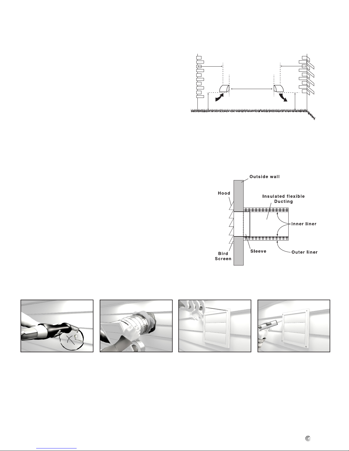
EXTERIOR DUCTING INSTALLATION
9
WEATHERHOOD LOCATION
OUTSIDE CORNER INSIDE CORNER
• Decide where your intake and exhaust hoods will be located.
Locating the Intake Weatherhood
• Should be located upstream (if there are prevailing winds) from the
exhaust outlet.
• At a minimum distance to 900 mm (3') away from dryer vents and furnace
exhaust (medium or high efficiency furnaces), driveways, oil fill pipes, gas
meters, or garbage containers.
• At a minimum height of 460mm (18’’) above the ground, or above the level
of expected snow accumulation.
• Ideally, keep weatherhoods 1m (3') from corners.
• Do not locate in the garage, attic, crawl space, or underneath deck.
Locating the Exhaust Weatherhood
• At least 460mm (18") above ground or above the depth of expected snow accumulation
• Ideally, keep weatherhoods 1m (3') from corners.
• Not near a gas meter, electric meter or a walkway where fog or ice could create a hazard
• Do not locate in a garage, workshop or other unheated space
INSTALLING THE DUCTING TO THE WEATHERHOODS
A well designed and installed ducting system will allow the ERV to operate at its
maximum efficiency. The inner liner of the flexible insulated duct must be secured to the
sleeve of the weatherhood (as close to the outside as possible) and to the appropriate duct
connection on the ERV. The insulation should remain full and not crushed. The outer liner,
which acts as a vapor barrier, must be completely sealed to the outer wall and the ERV
using tape and/or caulking. A good bead of high quality caulking (preferably acoustical
sealant) will seal the inner flexible duct to both the ERV duct connection and the
weatherhood prior to securing them.
To minimize airflow restriction, the flexible insulated duct that connects the two outside
weatherhoods to the ERV should be stretched tightly and be as short as possible.
Twisting or folding the duct will severely restrict airflow.
See “Installation Diagram Examples” for installation examples.
36" (1m)
min.
INTAKE
18" (460mm) min.
6' (2m)
min.
36” (1m)
min.
EXHAUST
18" (460mm) min.
STEPS FOR HOOD INSTALLATION:
1 Using the duct connection of
the outside hood, outline the
intake & exhaust holes to be
cut. The holes should be slightly
larger than the duct connection
to allow for the thickness of the
insulated flexible duct. Cut a
hole for both the intake and
exhaust hoods.
2 Pull the insulated flexible duct
through the opening until it is
well extended and straight.
Slide the duct’s inner vinyl sleeve
over the hood duct connection
and secure. Pull the insulation
over the duct and pull the vapor
barrier over the sleeve. Secure
with appropriate tape or
sealant.
3 Push the hood into the opening
and then attach the hood to the
outside wall with mounting
screws.
Repeat the installation
procedure for both the supply
and exhaust hoods.
4 Using a caulking gun, seal
around both hoods to prevent
any leaks.
fantech
Page 10
10
INTERIOR DUCTING INSTALLATION
• To maximize airflow through the ductwork system, all ducts should be kept short
and have as few bends or elbows as possible.
• 45º elbows are preferable to 90º.
• Use “Y“ ducts instead of “T” ducts whenever possible.
• All duct joints must be fastened with screws or duct sealant and wrapped with
aluminum foil duct tape to prevent leakage.
• Galvanized ducting from the ERV to the living areas in the house is recommended
whenever possible, although flexible ducting can be used in moderation when
necessary.
• To avoid possible noise transfer through the ductwork system, a short length
(approximately 300mm, 12’’) of nonmetallic flexible insulated duct should be
connected between the ERV and the supply/exhaust ductwork system.
• The main supply and return line to/from the ERV must have the same diameter as the
duct connection or larger.
• Branch lines to the individual rooms may be as small as 100mm (4’’).
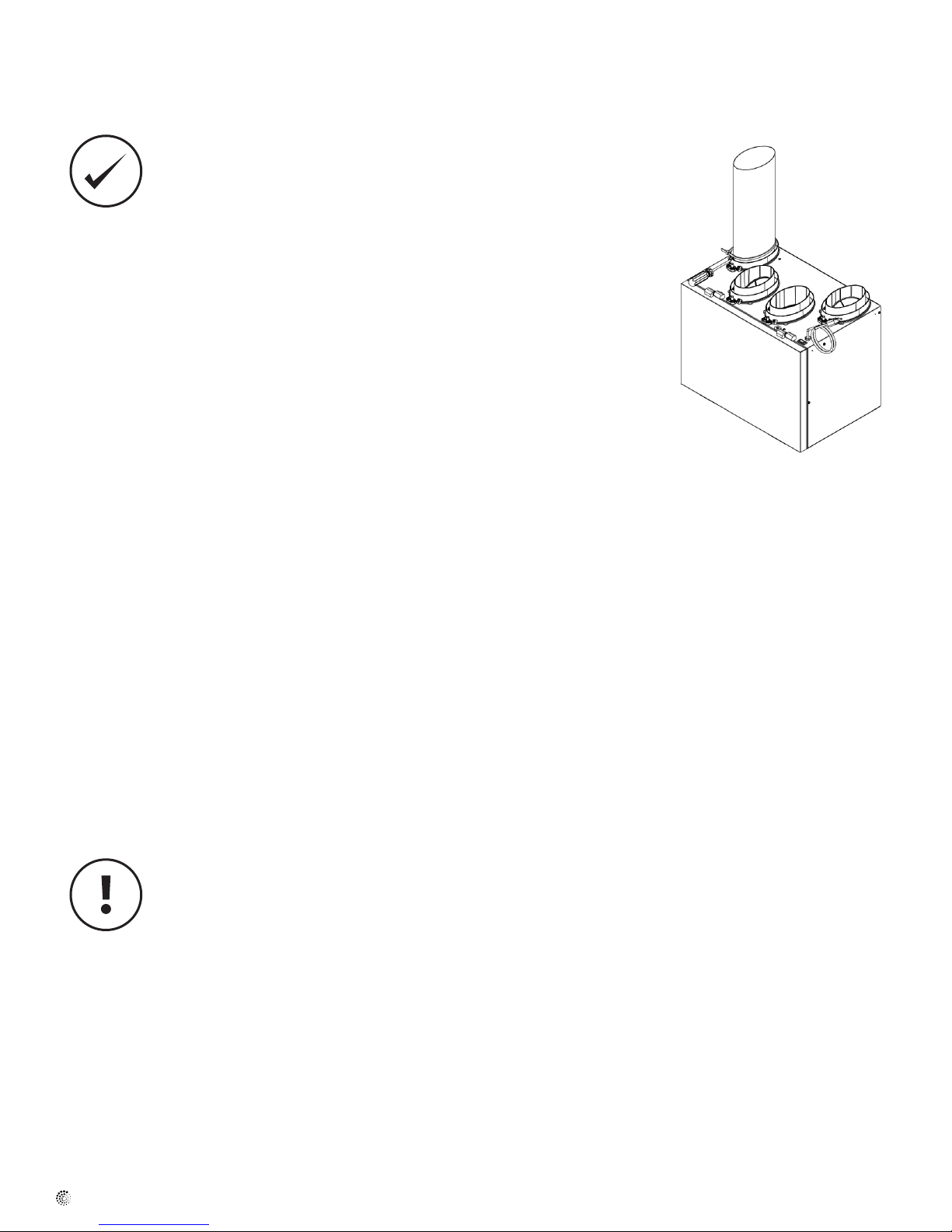
INSTALLING DUCT TO ERV
For flexible duct installation, slide flexible ducting onto duct connection. Then install a cable tie over flexible duct to prevent leakage between the ducting and
the duct connection.
In the case of solid ducting, slide duct over duct connection, screw in place and seal.
SUPPLY AIR GRILLES LOCATION
In homes without a forced air furnace, fresh air should be supplied to all habitable rooms, including bedrooms and living areas. It should be supplied
from high wall or ceiling locations. Grilles that diffuse the air comfortably are recommended. In homes with a forced air furnace, you may want to connect
the ERV to the furnace ductwork (see information below).
EXHAUST AIR GRILLES LOCATION
The stale air exhaust system is used to draw air from the points in the house where the worst air quality problems occur. It is recommended that return
air ducts be installed in the bathroom, kitchen, and laundry room. Additional return air ducts from strategic locations may be installed. The furnace
return duct may also be used to exhaust from. In this method, the exhaust air is not ducted back from bathrooms, kitchens, etc to the ERV with
“dedicated lines”.
As per building codes and installation requirements for combustion appliances:
Air return ducts, or openings for air return, should not be placed in enclosed spaces containing combustion
appliances that are subject to spillage.
fantech
Page 11
ERV INSTALLATION
LOCATION
The ERV must be located in a conditioned space where it will be possible to conveniently service the unit. Typically
the ERV would be located in the mechanical room or an area close to the outside wall where the weatherhoods will
be mounted. If a basement area is not convenient or does not exist, a utility room may be used.
Attic installation must meet the following conditions:
• Have a nearby power supply
(120 volts, 60Hz)
• Choose a location which
allows the possibility
of mounting the unit to
supporting beams.
• The unit should be level
in order to allow proper
condensate drainage
• To minimize noise, do not
install unit in living area
• Ensure proper drainage
• Attic temperature must be above freezing conditions at all times and for best performance should be 12°C
(54 °F).
• The condensate drain (if included) must be installed so that the condensate drains and is protected from freezing.
• The attic is easily accessible for equipment maintenance and inspection.
• Clothes dryer
• Range top
• Stovetop fan
• Central vacuum system
• Bathroom exhaust fans unless they are specifically designed for this purpose
These appliances may cause lint, dust or grease to collect in the ERV, damaging the unit.
11
Connecting appliances to the ERV is not recommended. These include:
Connecting any of these types of appliances to the ERV will void your warranty.
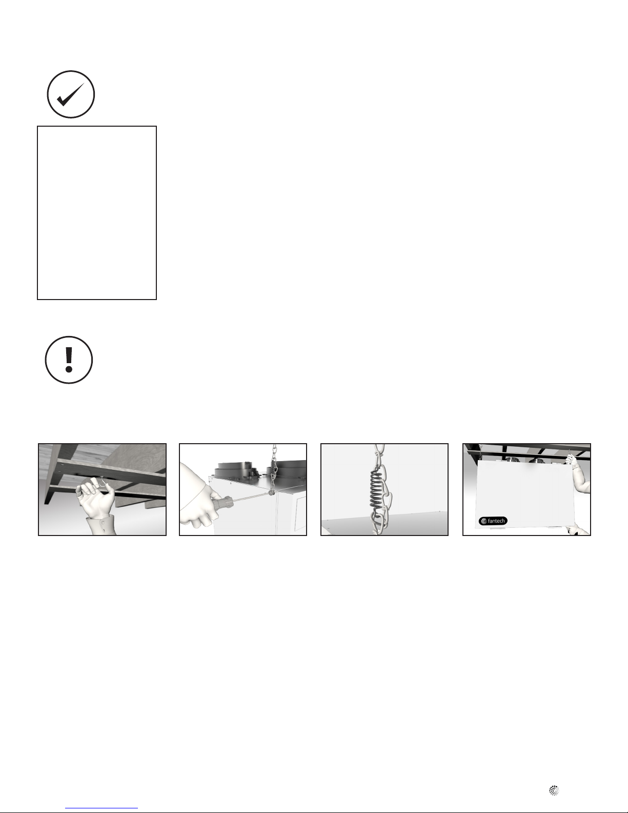
Mounting- Chain mount
1 Place fastening hooks on
the strapping board or
the oor joists.
2 Attach a hanging chain
(provided) to each 19 mm
(3/4") bolt (provided) in the
top 4 corners of the unit
and tighten.
3 Install a spring on each
chain. Hook the spring
in the links so a loop is
created in the chain. The
spring will then support the
unit's weight and absorb
vibrations.
4 Hang the unit by slipping
a link onto the hanging
hooks, making sure the
unit is level.
fantech
Page 12
12
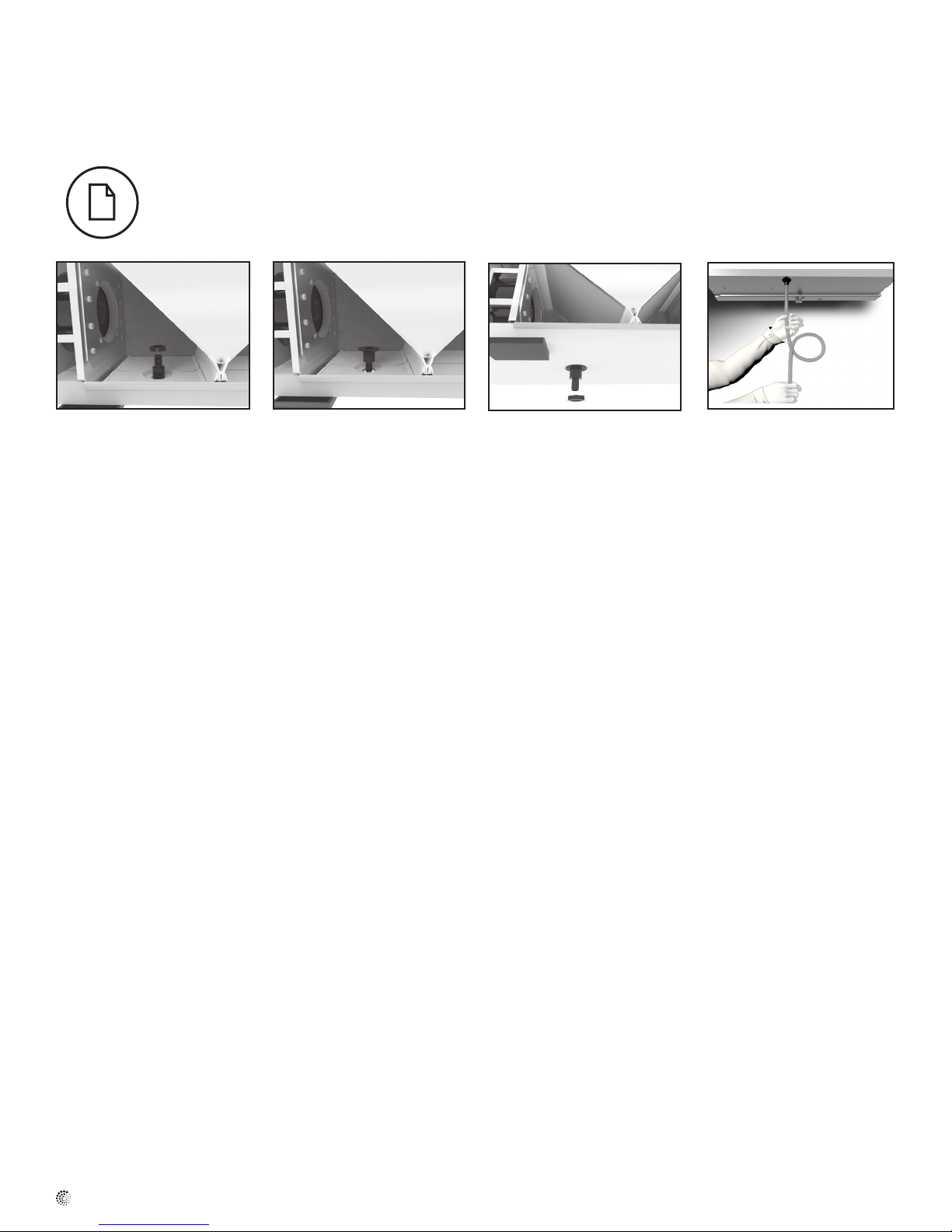
INSTALLING DRAIN LINE
Through normal operation and during its defrost mode, the ERV may produce some condensation. This water should flow into a nearby drain, or be taken
away by a condensate pump. The ERV and all condensate lines must be installed in a space where the temperature is maintained above the freezing point.
A “P” trap should be made in the drain line. This will prevent odors from being drawn back up into the unit.
The drain nipple is placed upside down in the unit to prevent it being damaged during shipping or the installation of the unit.
1 Remove the nutsert.
2 Invert the drain nipple. Make
sure to place gasket between
the unit and the drain nipple
inside the unit.
3 Secure the drain nipple using
the nutsert.
4 Install the drain hose making a
"P" trap, secure the
condensate line drain
connection using the tube
clamp provided.
Fill the condensate line with
water.
fantech
Page 13
13
AIRFLOW ADJUSTMENT & BALANCING
BALANCING THE AIRFLOWS IS CRUCIAL TO ENSURE OPTIMAL OPERATION OF THE UNIT. IF THE AIRFLOW IS NOT PROPERLY BALANCED, THE
FOLLOWING ISSUES MAY OCCUR:
• SIGNIFICANT POSITIVE OR NEGATIVE PRESSURE INSIDE THE HOUSE
• UNIT’S EFFICIENCY MAY BE NEGATIVELY AFFECTED
• UNIT’S DEFROST MAY NOT WORK EFFECTIVELY
• CAN LEAD TO AIR LEAKS OR BACKDRAFTING OF ANY COMBUSTION APPLIANCES.
The airflow adjustment and balancing procedure consists of adjusting the fresh airflow to make sure it meets the requirements for the building and then
balance the system to make sure there is an equal amount of stale air being exhausted. In the case that the airflow is not exactly the same, it is
recommended to have a higher stale airflow of up to 10% in colder climates to ensure that the temperature of the fresh airflow coming from the outside
is as close to the room temperature as possible.
GENERAL PREPARATION:
Before performing the adjustment and balancing for unit, make sure to check the following:
• Seal all the ductwork
• Fully open all dampers (if present)
• Turn off all other exhaust appliances such as range hood, dryers, bathroom fans, etc.
• If performing balancing during cold weather, make sure the unit is not operating in defrost mode.
• If the installation type is Simplified or Partially Dedicated, make sure that the furnace/air handler blower is operating at normal speed during
the balancing sequence.
• When reading with a mechanical type manometer (Magnehelic), make sure the manometer is placed on a level surface
For optimal performance, ERV unit should be re-balanced after a major renovation or after the installation of extra grilles or registers.
• In cold climates, continuous excessive positive pressure inside the house may drive moisture inside the external walls of the
house. Moisture present inside the external wall may condense if the outside temperature is cold enough and can cause damage
to structural components. A symptom of excessive positive pressure inside a house is frozen door locks.
• Continuous excessive negative pressure can have undesirable effects. In some geographic locations, negative pressure can
increase the infiltration of soil gases such as methane and radon. Negative pressure is also undesirable where combustion
equipment is present and may cause back drafting of the combustion gases.
ADJUSTING AIRFLOWS USING INTEGRATED BALANCING SYSTEM
Adjustable dampers are integrated into the Fresh Air to Building and the Stale Air to Outside duct connections. Those dampers replace the installation of
separate back draft and balancing dampers in the duct line.
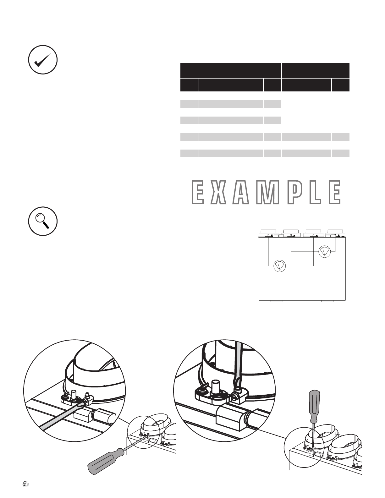
The integrated dampers are preset at the fully opened position. In order to reduce the amount of airflow, turn the adjustable lever using a flat screw driver
by turning it counter clock wise. Turning the lever clockwise may damage the plastic screw head. Follow the balancing steps to properly adjust the airflow.
fantech
Page 14
14
BALANCING STEPS
Use balancing chart located on the
door of the ERV
Airow Normal Speed Reduced Speed
STEP #1: Identify the desired airflow using the provided chart. From
the desired airflow (left column) identify the pressure reading
needed by simply following the line. Make sure to set the unit at
the Normal speed before performing the next step.
STEP #2: Measure the pressure reading by connecting a manometer
on the LOW and HIGH pressure ports located on the duct
connection. Refer to Illustration #1. If the pressure reading is
LOWER than the desired value, adjust the balancing dampers by
turning the adjustable arm counter clockwise until the correct
corresponding pressure value is reached. Refer to Illustration #2
Do the same for both the SUPPLY and EXHAUST airflows. If the
pressure reading is HIGHER than desired when the damper is fully
opened, please check the distribution system for any anomalies
that could increase the resistance in the distribution system.
• If the house is tightly sealed, adjusting one airflow
may affect the other airflow as well. It is recommended to check each airflow
again to make sure the value did not change dramatically during the
balancing procedure. Make adjustments as necessary.
• The pressure reading from the duct connection refers to the total pressure
loss from the distribution system. A well designed distribution system should
have a total pressure loss between 0.4” (100Pa) and 0.6” (150Pa). The
pressure reading can therefore be used to troubleshoot distribution system.
If the pressure reading is higher than 0.6” (150Pa), we recommend that you
inspect the system and check for closed grilles, blocked exterior hoods or
twisted flexible duct.
STEP #3: Secure the adjustable arm by tightening the set screw as shown in Illustration #3.
CFM L/s
110 52 0.36 91
100 47 0.46 114
90 42 0.55 137
80 38 0.64 161
70 33 0.74 184 0.13 32
65 31 0.78 195 0.16 40
60 28 0.83 207 0.19 48
55 26 0.87 219 0.22 55
50 24 0.92 230 0.25 63
Pressure reading
BALANCING CHART (example only)
∆In W.G.
∆Pa
HIGH LOW LOW HIGH
Pressure reading
EXHAUST
∆In W.G.
SUPPLY
∆Pa
Adjustment lever (in front)
fantech
Illustration #1
Set screw (on top)
Illustration #3Illustration #2
Page 15
Low Voltage Control Systems
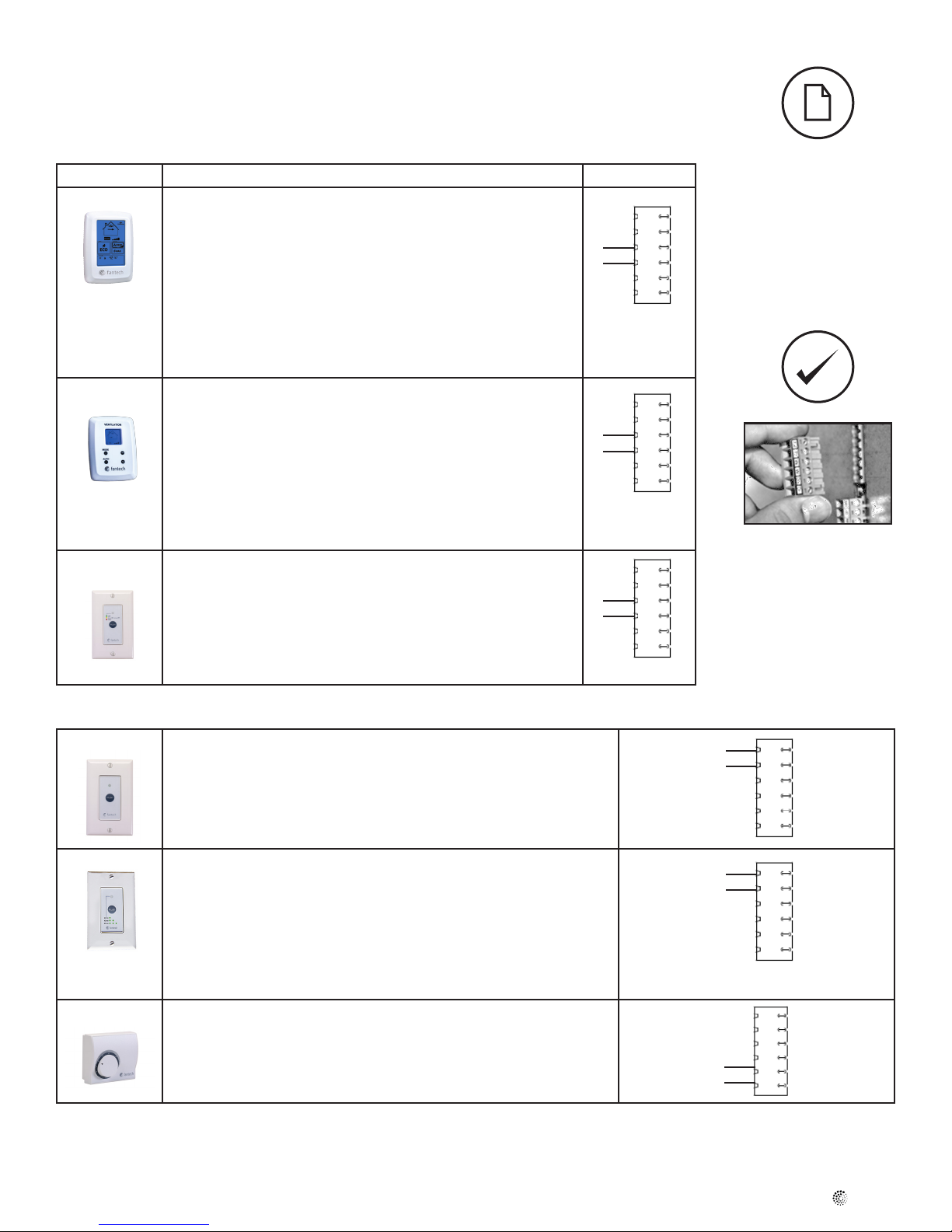
* Please see instruction manuals for individual controls for proper wiring and set up of control systems.
CENTRAL CONTROLS
These control options can only be used individually
CONTROLS FEATURES CONNECT TO
ECO-Touch® • Our most complete, yet easy to use control system
• Sleek design with backlight touchscreen LCD
• ECO mode selects the best operating mode and speed for the season,
minimizing energy use associated with ventilation
• Set preferred indoor relative humidity range and ventilation mode for day
and night conditions
• No battery to replace, all programmed settings are retained during power
outage
• Maintenance reminder indicator
• Error code messages reduce troubleshooting time
EDF7
EDF1 • Press button once for continuous Reduced speed
• MODE button provides 3 modes of operations: Ventilation , Recirculation and Standby
• User selected fan speed: Reduced, Medium, Normal and 20 minutes
per hour
• AUTO setting allows the homeowner to deactivate the dehumidistat
• When the humidity exceeds the desired setpoint, the ventilation system operates at Normal speed.
• Once the desired humidity level is achieved, your ventilation system
resumes to its previous mode of operation
• Press button twice and the unit will cycle 20 minutes ON/ 40 minutes
OFF and repeat
• EDF1 – Press button a third time and the system will run continuously
on HIGH speed
W
W
W
W
W
W
15
1. Ensure that unit is not
plugged when connecting
the control
2. Recirculation mode is only
available with the “R” sufx
at the end of the model
number.
The wiring connectors
can be removed for
easier connection.
*Maintain polarity
between control
and ERV
(+ → + ; - → -)
AUXILIARY CONTROL – These controls can be paired
RTS2*
RTS5
MDEH1 • Rotary dial Dehumidistat
• 20- minute timer with LED light
• Boosts system to high speed with the touch of a button
• Up to 5 can be used in one system
• Use in bathroom, kitchen, laundry room
• 20/40/60 minute timer with LED light
• Boosts system to high speed with the touch of a button
• Up to 5 can be used in one system
• Use in bathroom, kitchen, laundry room
• Multiple units can be used
• We recommend setting the relative humidity above 80% during the summer
+T
-T
+T
-T
D
D
fantech
Page 16
16
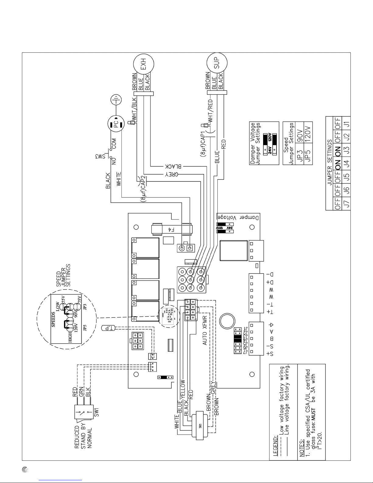
WIRING DIAGRAM
Observe polarity on all accessory controls where
applicable.
fantech
Page 17
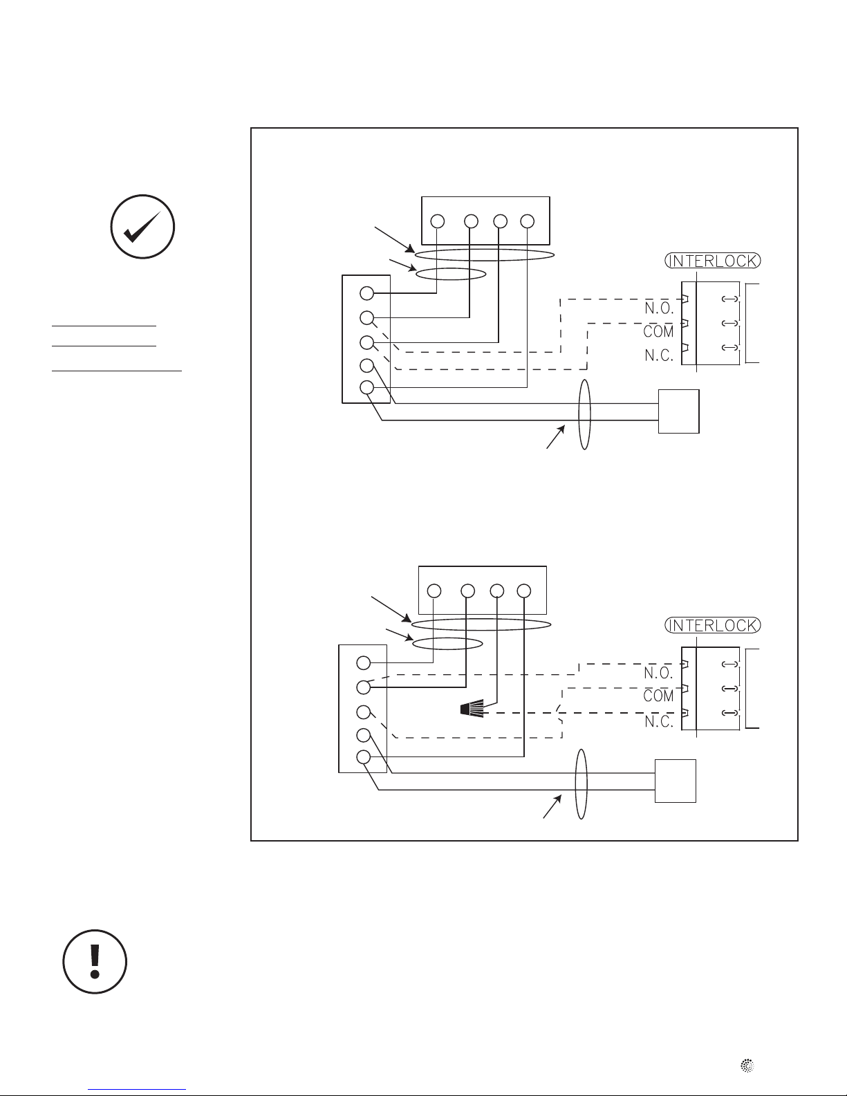
WIRING DIAGRAM (CONT'D)
17
WIRING DIAGRAM TO
FURNACE
FOR A FURNACE
CONNECTION TO
A COOLING SYSTEM:
On some newer furnaces and older
thermostats, energizing the R and
G terminal at the furnace has the
effect of energizing the Y at the
thermostat and thereby turning on
the cooling system. If you identify this
type of thermostat, you must use the
“Alternate Furnace Interlock Wiring”
FURNACE
24-VOLT
TERMINAL BLOCK
FOUR
WIRE
TWO WIRE
heating only
W
R
G
C
Y
Standard Accessory Control Contact
Standard Furnace Interlock Wiring
THERMOSTAT
TERMINALS
R G
W
Alternative Accessory Control Contact
Alternate Furnace Interlock Wiring
THERMOSTAT
TERMINALS
Y
TWO
WIRE
COOLING SYSTEM
R G
FURNACE
24-VOLT
TERMINAL BLOCK
FOUR
WIRE
TWO WIRE
heating only
W
R
G
C
Y
W
WIRE JOINT
Y
TWO
WIRE
COOLING SYSTEM
As per building codes and installation requirements for combustion appliances:
Air return ducts, or openings for air return, should not be placed in enclosed spaces containing combustion
appliances that are subject to spillage.
fantech
Page 18
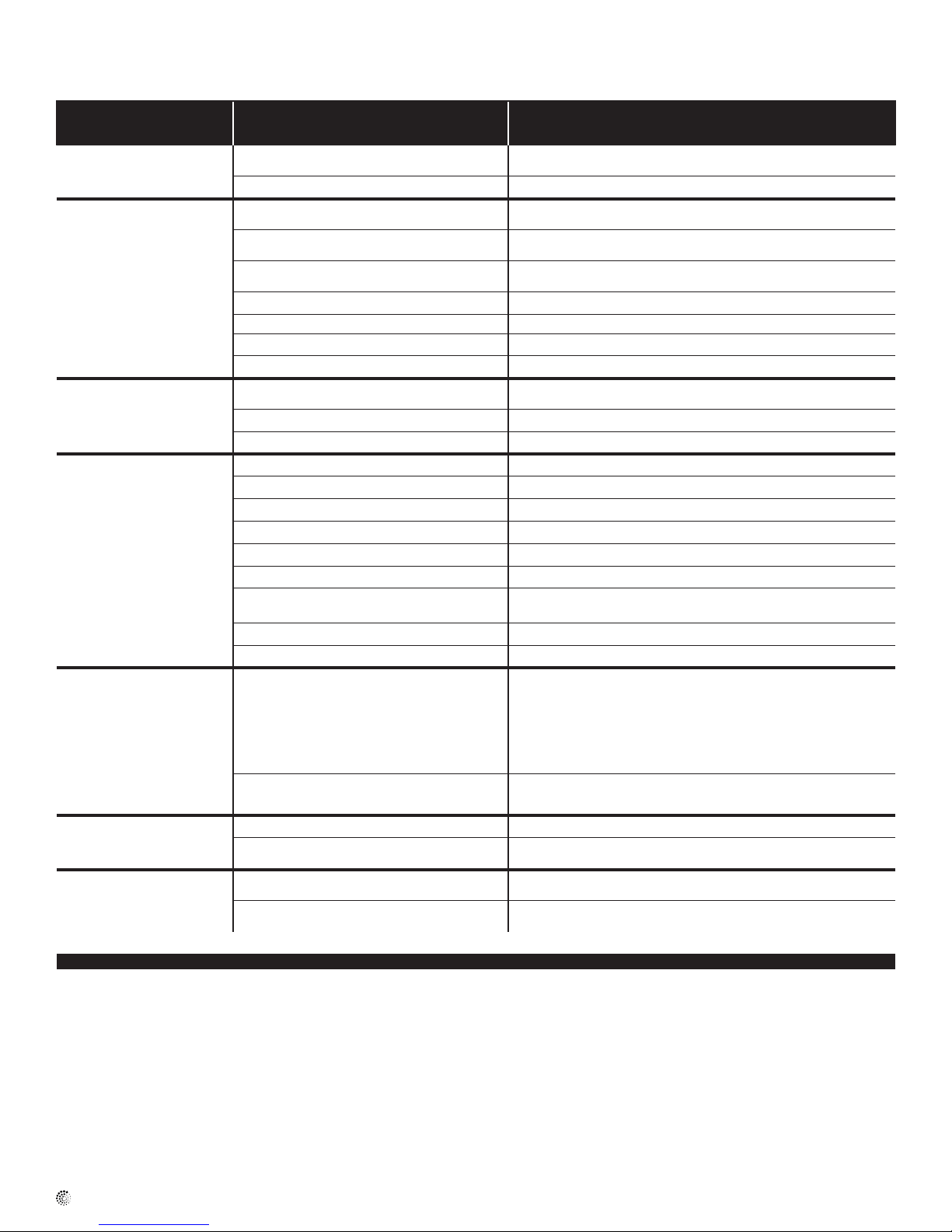
18
TROUBLESHOOTING
Problem Causes Solutions
Air is too dry Dehumidistat control is set too low Increase the desired level of humidity. Change ventilation mode from
ERV out of balance Have contractor balance ERV airows
Air is too humid Dehumidistat control is set too high Reduce the desired level of humidity. Combine this with the use of continuous
Sudden change in temperature Wait until outside temperature stabilizes (winter). Heating will also improve
Storing too much wood for heating Store a majority of your wood outside. Even dried, a cord of wood contains
Dryer vent exhaust is inside home Make sure the dryer vent is exhausting outside.
Poor air circulation near windows Open curtains or blinds.
ERV out of balance Have contractor balance ERV airows
Well sealed basement door is closed Open the door or install a grill on the door.
Persistent condensation
on window
Poor Air Flows 1/4" (6mm) mesh on the outside hoods is plugged Clean exterior hoods or vents
Supply air feels cold Poor location of supply grilles, the airow may irritate
Improper adjustment of dehumidistat control Reduce the desired level of humidity. Combine this step with use of continuous
ERV out of balance Have contractor balance ERV
Poor air circulation near windows Open curtains or blinds.
Filters plugged Remove and clean lter
Core obstructed Remove and clean core
Indoor grilles closed or blocked Check and open grilles
Inadequate power supply at site Have electrician check supply voltage
Ductwork is restricting airow Check duct installation
Improper speed control setting Increase the speed of the ERV (i.e. change unit control from REDUCED to NORMAL
ERV airow improperly balanced Have contractor balance ERV airows
Ducting has fallen down or been disconnected from ERV Have contractor reconnect ducting
the occupant
Outdoor temperature extremely cold If supply air is ducted into furnace return, the furnace fan may need to run
continuous mode to standby.
exchange mode.
situation.
more than 20 gallons of water.
exchange mode.
speed)
Locate the grilles high on the walls or under the baseboards, install ceiling
mounted diffuser or grilles so as not to directly spill the supply air on the
occupant (eg. Over a sofa)
Turn down the ERV supply speed. A small duct heater (1kw) could be used to
temper the supply air
Placement of furniture or closed doors is restricting the movement of air in
the home
continuously to distribute ventilation air comfortably
ERV and/or Ducts frosting up ERV air ows are improperly balanced Have HVAC contractor balance the ERV airows
Malfunction of the ERV defrost system Note: minimal frost build-up is expected on the core before unit initiates
Condensation or Ice Build Up in
Insulated Duct to the Outside
Note: It is best to get the unit checked by a certied HVAC Contractor/Technician.
Incomplete vapor barrier around insulated duct Tape and seal all joints
A hole or tear in outer duct covering Tape any holes or tears made in the outer duct covering
fantech
defrost cycle functions
Ensure that the vapor barrier is completely sealed.
Page 19
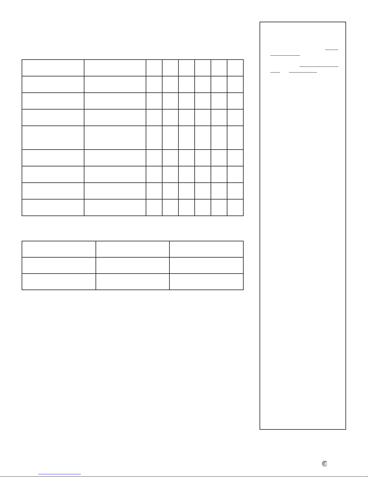
ERV MAINTENANCE CHART
Maintenance Required Recommended Frequency Date Maintenance Performed
Check and Clean Filters Every 3 months or if
dirty
Check Engery Recovery
Core
Check Drain Pan and
Lines
Vacuum the Inside of the
Unit
Clean and Un-block
Outside
Hoods
Clean and Inspect Duct
Work
General Servicing by a
Qualied Contractor
Every 6 months
Every 3 months
Annually
Annually
Annually
Annually
19
Limited Warranty
• The Energy recovery core has limited
5 year warranty.
• The warranty is limited to 5 years on
parts and 7 years on fans from the
date of purchase, including parts
replaced during this time period. If
there is no proof of purchase
available, the date associated with
the serial number will be used for the
beginning of the warranty period.
• The fans found in all Fantech ERVs
require no lubrication, and are factory
balanced to prevent vibration and
promote silent operation.
• The limited warranty covers normal
use. It does not apply to any
defects, malfunctions or failures as
a result of improper installation,
abuse, mishandling, misapplication,
fortuitous occurrence or any other
circumstances outside Fantech’s
control.
* Schedule may be altered to meet your own needs. More frequent servicing may be required depending on the
severity of your home's indoor and outdoor environments.
Contractor Telephone Number Date Serviced
• Inappropriate installation or
maintenance may result in the
cancellation of the warranty.
• Any unauthorized work will result in
the cancellation of the warranty.
• Fantech is not responsible for any
incidental or consequential
damages incurred in the use of the
ventilation system.
• Fantech is not responsible for
providing an authorized service
centre near the purchaser or in the
general area.
• Fantech reserves the right to supply
refurbished parts as replacements.
• Transportation, removal and
installation fees are the responsibility
of the purchaser.
• The purchaser is responsible to
adhering to all codes in effect in his
area.
* This warranty is the exclusive and only warranty in
effect relative to the ventilation system and all other
warranties either expressed or implied are invalid.
fantech
Page 20
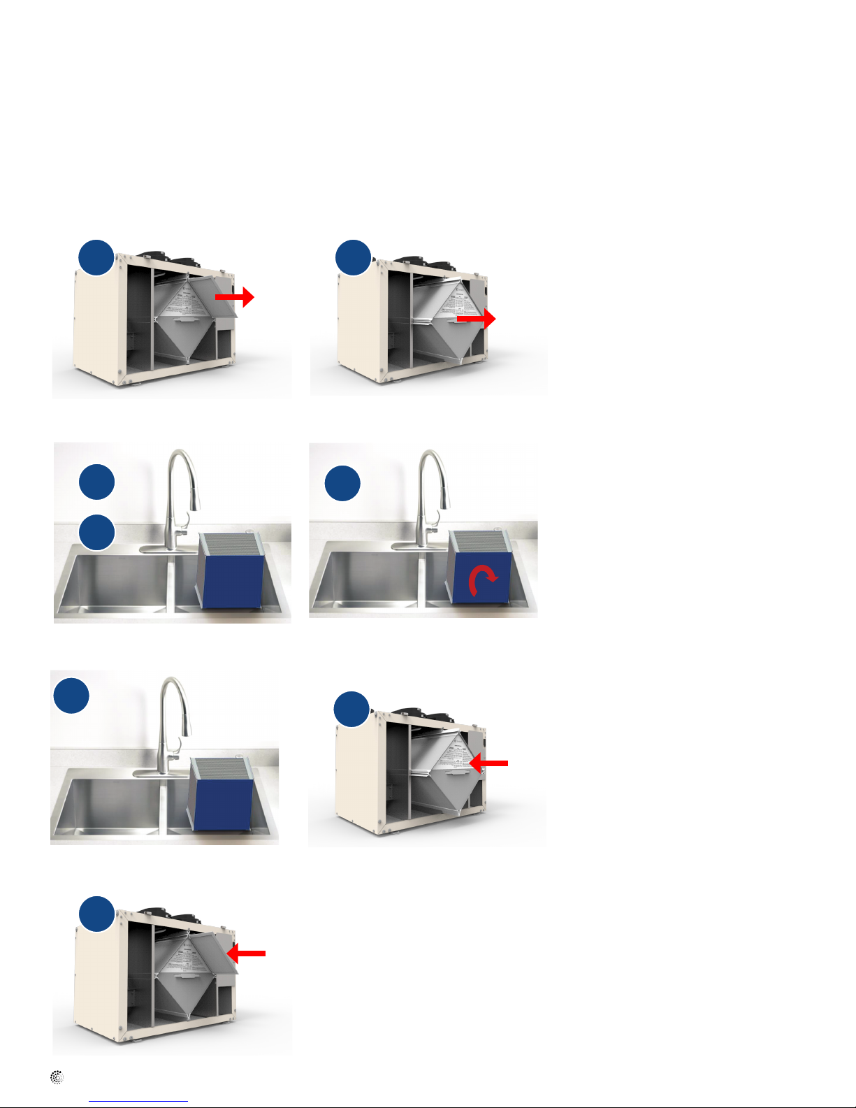
20
ERV core washing instructions
For proper maintenance of your energy recovery core please follow these instructions
1 Remove both lters by sliding them out.
2 Remove the core from the unit.
1 2
3
4
5
3 With one of your core's air inlets facing
down, place it in a large sink, bathtub, or
shower.
4 Pour clean tap water through the face of the
core facing upwards until it runs clear.
Ensure the entire surface is rinsed.
5 Rotate the core so that its other air inlet is
facing down and repeat step 5.
6 With plates still oriented vertically allow the
core to dry, normally 2-3 hours.
7 Slide back the core into the unit
8 Replace both lters.
6
8
fantech
7
Page 21
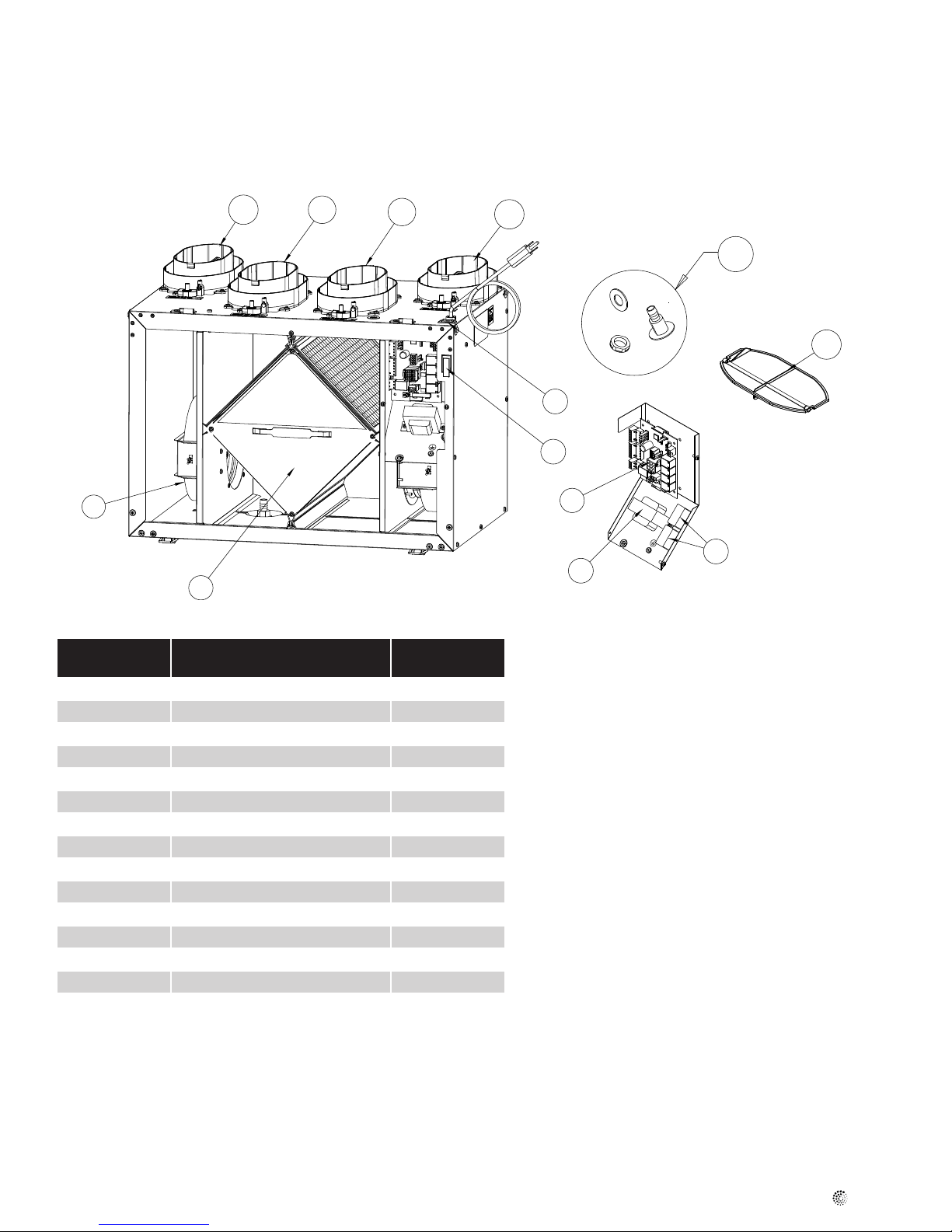
Parts list
21
1110
1
3
BOM # Description
1 R2E 190 Radical, Rep. Kit 405520
2 Electrostatic Filters Kit 8.5” x 15” 402041
3 Energy Recovery Cell, 9" x 9" x 15" 427473
4 Capacitors 8uF 410012
5 Kit,PCB Replacement,Board,AC* 422677
6 Door Switch 410867
7 Auto-Transformer 411963
8 Control Switch 410213
9 Kit Drain Plug 40315
10 Collar 6”, Oval, w/Stop 413893
11 Collar 6”, Oval, wo/Stop 413894
12 Damper Door, VHR150R 420462
Temperature Probe 40286
Door Assembly 422806
Kit, Chain 404261
11
10
9
12
8
6
5
4
7
VER150
(78112)
fantech
Page 22

22
Notes
fantech
Page 23

Notes
23
fantech
Page 24

Fantech reserves the right to make technical changes.
For updated documentation please refer to www.fantech.net
Fantech®
Fantech se réserve le droit de faire des changements techniques. Pour de la documentation à jour, s'il vous plaît se
référer au www.fantech.net
 Loading...