

Page 1
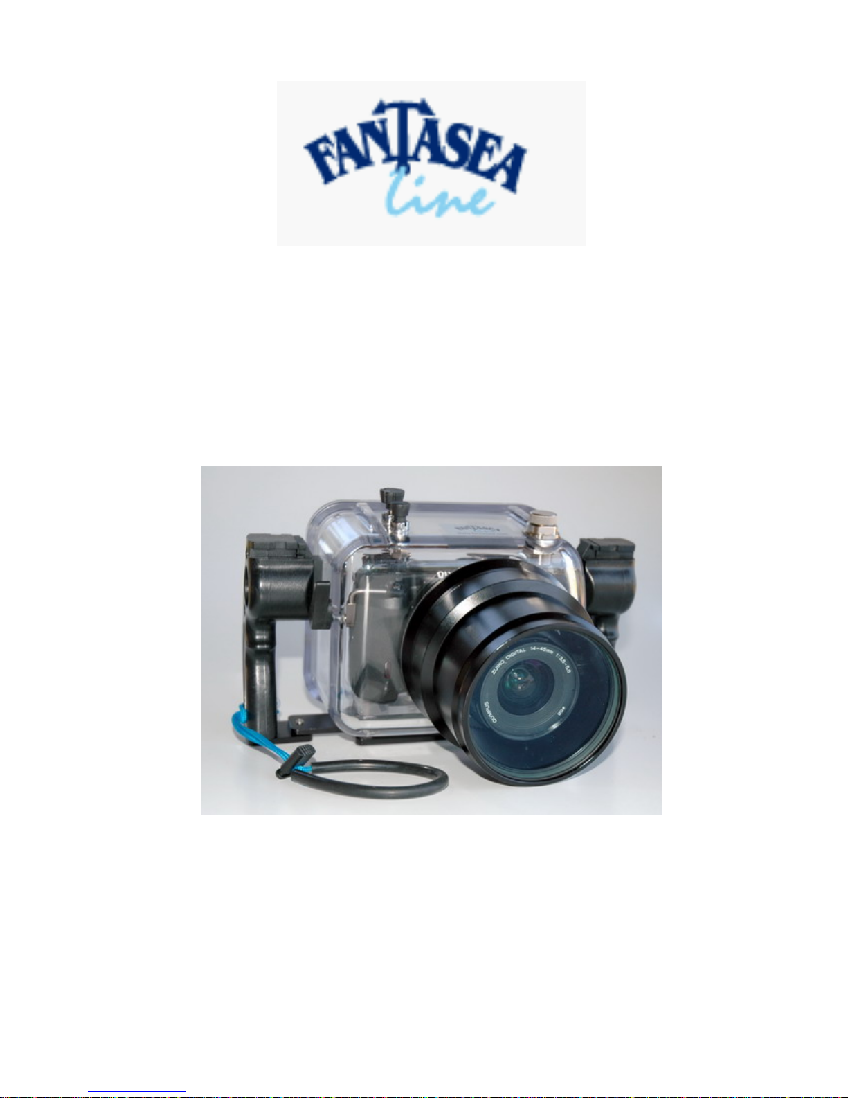
Manual for Fantasea FE 330 Camera Housing
For the Olympus E330 Camera
1
Page 2

Table of Contents
MANUAL FOR FANTASEA FE 330 CAMERA HOUSING FOR THE OLYMPUS E330
CAMERA-----------------------------------------------------------------------------------------------------------1
INTRODUCTION ------------------------------------------------------------------------------------------------3
GENERAL SPECIFICATIONS -------------------------------------------------------------------------------4
FEATURES AND ACCESSORIES INCLUDED WITH THE HOUSING----------------------------4
FEATURES ---------------------------------------------------------------------------------------------------------4
ACCESSORIES INCLUDED ----------------------------------------------------------------------------------------4
FUNCTIONS [CONTROL DETAILS]-----------------------------------------------------------------------5
MAINTENANCE OF THE GASKET SEAL -------------------------------------------------------------------------7
EXCLUSIVE PRESSURE RELEASE PLUG---------------------------------------------------------------9
OPENING LEVERS----------------------------------------------------------------------------------------------- 10
MOUNTING THE CAMERA IN THE HOUSING------------------------------------------------------------------ 11
CLOSE HOUSING------------------------------------------------------------------------------------------------ 12
USE & CARE OF HOUSING -------------------------------------------------------------------------------- 14
PRE DIVE FUNCTION CHECK ---------------------------------------------------------------------------------- 14
GENERAL OPERATION ----------------------------------------------------------------------------------------- 14
CLEANING & STORAGE------------------------------------------------------------------------------------ 14
CARE AND MAINTENANCE ------------------------------------------------------------------------------------ 14
TRAVELING ----------------------------------------------------------------------------------------------------- 15
ACCIDENTS------------------------------------------------------------------------------------------------------ 15
SERVICE --------------------------------------------------------------------------------------------------------- 15
WARRANTY ---------------------------------------------------------------------------------------------------- 16
2
Page 3

INTRODUCTION
For the first time, the comfort and flexibility of continuous live views directly on the LCD is available
to digital SLR users. This ground-breaking innovation enables framing of shots without the need to
look through the viewfinder. Users can therefore see what’s going on around them while they shoot,
which is a significant advantage for sports photographers as well underwater photography.
The Olympus E330 is the world's first interchangeable lens digital SLR to offer a true "Live View"
image on the LCD screen, in addition to the optical viewfinder. The Olympus E330's LCD is
“articulated” it can extend out from the camera body and swivel downward or upward. This of course
is for land use, while diving. the LCD will be in a stationary position
The purpose of this manual is to provide you with the basic introduction to your Olympus E330,
which should get you comfortable with the housing and allow you to get started taking great
underwater images right away. We strongly urge you to thoroughly read the Olympus E330
instruction manual as well to familiarize yourself with the most common controls and settings that
you will use for your underwater photography. The FE330 housing will permit access to most of the
important controls on the camera. To take full advantage of these features, it is recommended to have
a good command of what each option can do for you, so you will know when you should use each
specific control.
3
Page 4

GENERAL SPECIFICATIONS
• Test Pressure Fantasea Housings are individually tested to 300 feet
• Closure Design Air Lock
• Body Material Polycarbonate
• Overall Size 210 x 270 x 200 mm (LxWxH)
• Total Weight Approximately 2.46 Kg (Housing only)
• Buoyancy
(with camera) Slightly buoyant
FEATURES AND ACCESSORIES INCLUDED WITH THE
HOUSING
Features
• Visible main gasket seal for final pre-dive check
• Double O-ring design on all controls
• Bulkhead and hotshoe plug for external TTL strobe
• Zoom Port 14mm ~ 45mm
Accessories Included
• Spare main gasket seal
• Universal tool
• Silicone O-ring grease
• Carry bag
• Cleaning Kit
4
Page 5
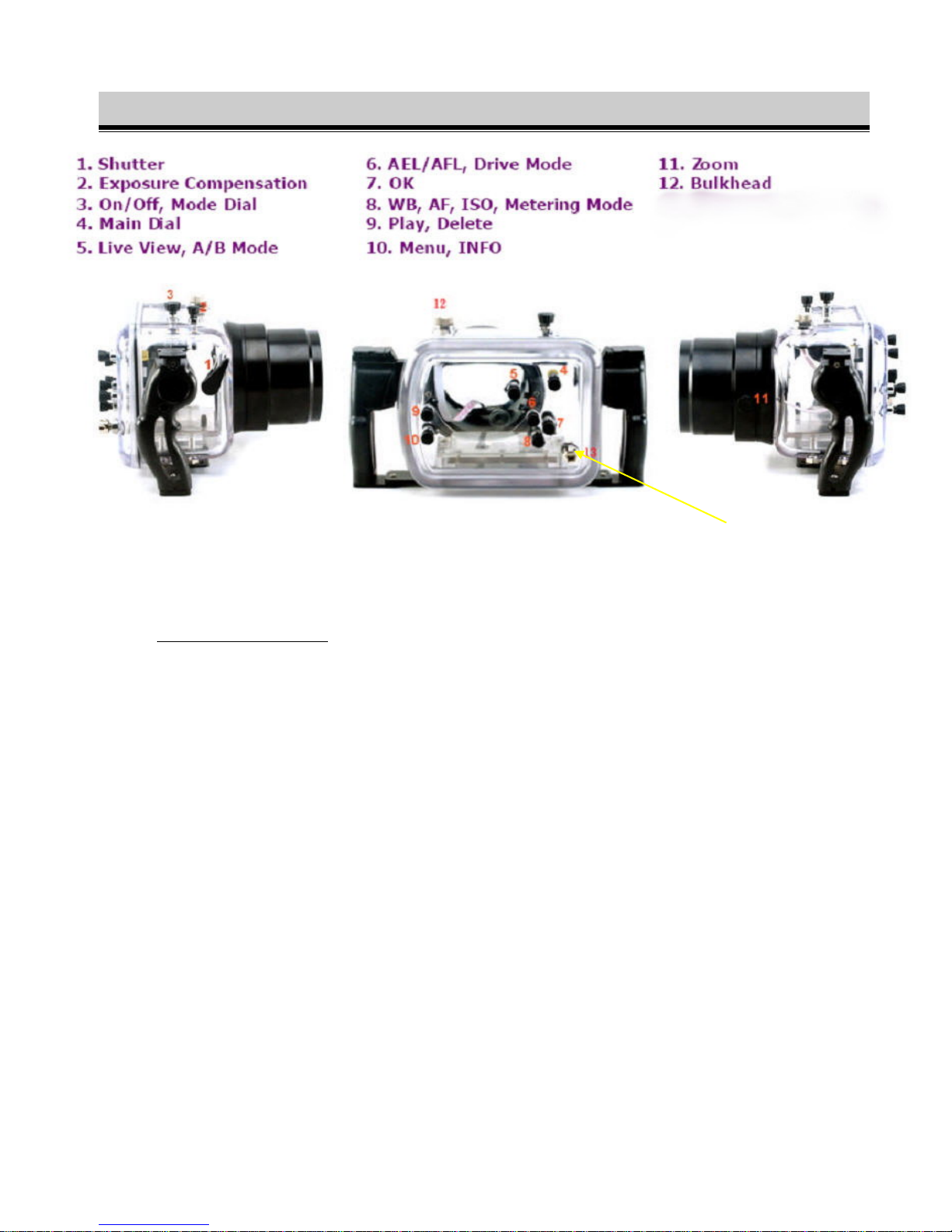
FUNCTIONS [CONTROL DETAILS]
1 Shutter:
Main Trigger [Shutter]
FIGURE 1: CAMERA HOUSING IN THREE VIEWS
Pressure Release Plug
Depress halfway to set the and fully depress to activate shutter.
2 Exposure Compensation:
Set exposure compensation press button to choose amount of compensation.
3 On/Off and Mode Dial:
Dual purpose button—sets camera on or off and can target a mode by twisting the button.
Modes dealing with aperture and shutter speed and scene selection modes.
4 Main Control Dial:
When any selection of the rotary wheel is pressed, the display will be visible on the monitor.
They are set when the Control Dial is rotated while looking at the menu.
5 Live View/ A and B Mode:
This button operates dual buttons. The Live View button displays the subject on the monitor
A Mode: full time Live View
B Mode: Macro Live View
5
Page 6

6 Drive and AEL/AFL button:
Dual purpose button to operate 2 buttons:
Drive—sets the single-frame/sequential shooting, remote control and self timer
AEL/AFL button—locks focus and exposure settings prior to shooting.
7 OK button:
Selects [confirms] selection. Used to set and confirm changes to the multi control settings of
the multipurpose button [button #8].
8 Multi Selector button:
This button controls the multi-functional button. Functions include: Metering button, White
balance button, Auto Focus button and ISO button.
9 Playback/Delete button:
Another instance in which this button acts upon 2 camera buttons.
Playback displays the last picture taken.
Playback the image you want to delete and press the Delete button. To confirm deleted
selection, press the OK button [button #7].
10 Menu/Info button:
Pressing the Menu button displays the menu on the monitor. Use the multi selector button to
make a selection [button #8] and confirm the selection with the OK button [button #7].
If the Control Panel screen does not appear, pressing this button [Info] will cause the
information to appear.
11 Zoom Control:
This button activates the zoom lens of the camera. Refer to the section called "Attaching the
Zoom Control Guide Ring" for further information.
12 Sync Port Bulkhead:
5 pin sync port for attaching sync cord to camera housing.
13 Pressure Release Plug:
Unique pressure release plug used to open or seal camera housing.
6
Page 7

Maintenance of the Gasket Seal
Each housing is individually inspected and hydrostatically tested in the factory. The design of the
compression gasket seal is among the most reliable in the industry and the watertight integrity is
excellent. This special gasket design provides a perfect seal even if there is any movement between
the body and lid due to change of ambient pressure.
With this in mind…
The gasket seal is the only barrier between the water outside and the air space within the flash. It is an
effective barrier only if the seal is properly maintained. The gasket seal should be inspected before
every dive. The following information is provided for your guidance in using and maintaining the
gasket seal.
Maintaining the gasket Seal
If the main body to lid gasket is not installed, install the gasket before diving. This is the only user
serviceable gasket. Its care and maintenance is critical to the watertight integrity of the housing. The
gasket should be replaced at the proper service interval (see Section on Service). If the gasket is
contaminated, or not already installed, inspect and install the gasket according to the following
guidelines.
Guidelines for Inspection, Cleaning and Re-Instillation of the Gasket
Materials Needed:
You will require a soft cotton cloth or q-tip. Make sure these are free of all chemicals or
contamination such as loose fibers You can moisten the cotton or cloth and wipe the surface of gasket
clean—no silicon grease or lubricant is necessary It is advised to carry out the following procedure on
a firm clean level surface, e.g. at a table), to prevent skidding. This is especially useful if you are
doing this maintenance from your diving boat as it moves.
When to Maintain the O-Ring Seal:
Remove the O-ring periodically for inspection. It is not necessary to remove, clean and re-install the
O-ring after every dive provided the O-ring did not become contaminated. The housing may be
required to be opened between dives, to replace memory card or recharge the batteries. Before
opening, make sure the outside of the housing is thoroughly toweled dry. After removing the lid and
servicing the camera, replace the lid straight away rather than leaving it lying around. Before
replacing the lid, make sure that no contamination such as dust, hair, salt, etc. has fallen onto the
gasket recess. As a precaution we recommend visually inspecting the gasket every time the lid is
opened and before it is sealed.
7
Page 8
Procedure for Gasket Maintenance:
1. Place the lid on a firm non-slip level surface.
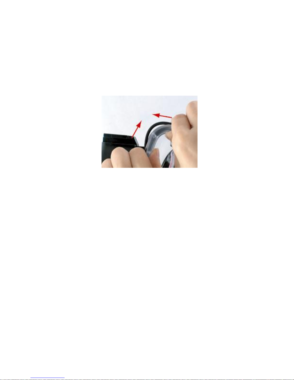
2. The gasket can be extracted using a gasket extractor tool (make
sure the tool has no sharp edges). Alternatively use the flat
surface of your thumbs to gently stretch the gasket on two faces
[Figure 2] thus making a small loop protruding a few mm. The
loop can then be grasped between finger and thumb, to pull the
gasket over the lip.
FIGURE 2: PROVIDING A LOOP IN THE O-RING
3. Clean the seal recess (the square groove where the gasket sits)
with a cotton bud.
4. Inspect the gasket all the way round its surface for damage such
as cuts tears or contamination. This should be done visually and
also by feeling the surface texture between finger and thumb.
5. IF THE GASKET IS DAMAGED OR SUSPECTED OF
BEING DAMAGED, DISCARD IT IMMEDIATELY. A spare
gasket is supplied with your housing, or a replacement gasket
can be obtained from Fantasea. If the gasket is contaminated or
suspected of being contaminated, clean it with a cotton cloth
that is free of all chemicals or contamination. After cleaning
inspect the gasket again.
6. Replace the gasket into the groove; run a finger round the
gasket to make sure it is snugly seated in the groove.
8
Page 9
Exclusive Pressure Release Plug
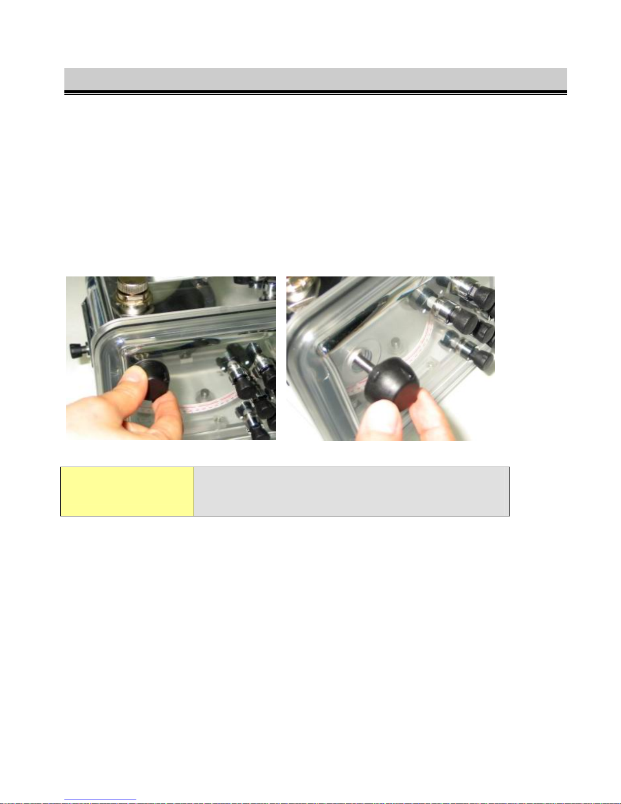
The body and lid are uniquely designed with a "no clip" closure arrangement. Our testing has shown
that this arrangement allows the water to exert an even pressure on the O-ring, thus increasing the
reliability of the watertight seal. To open the housing, the pressure release plug must be first
unscrewed and then pulled all the way out. This provides a channel for the air to pass though and
eliminate the pressure differential between the inside of the housing and the ambient air pressure.
The plug consists of an internal double O-ring seal on a stainless steel slide shaft. These internal Orings form the watertight seal. There is also a large outer O-ring under the knob. This O-ring serves to
prevent contamination [dirt or salt] of the slide shaft, and is not required for watertight integrity. If
this O-ring should become detached, it can simply be pushed back in place.
Important!
Before diving, make sure the pressure release
plug is pushed closed, and then screwed home, do
not over tighten this plug (finger tighten only).
9
Page 10
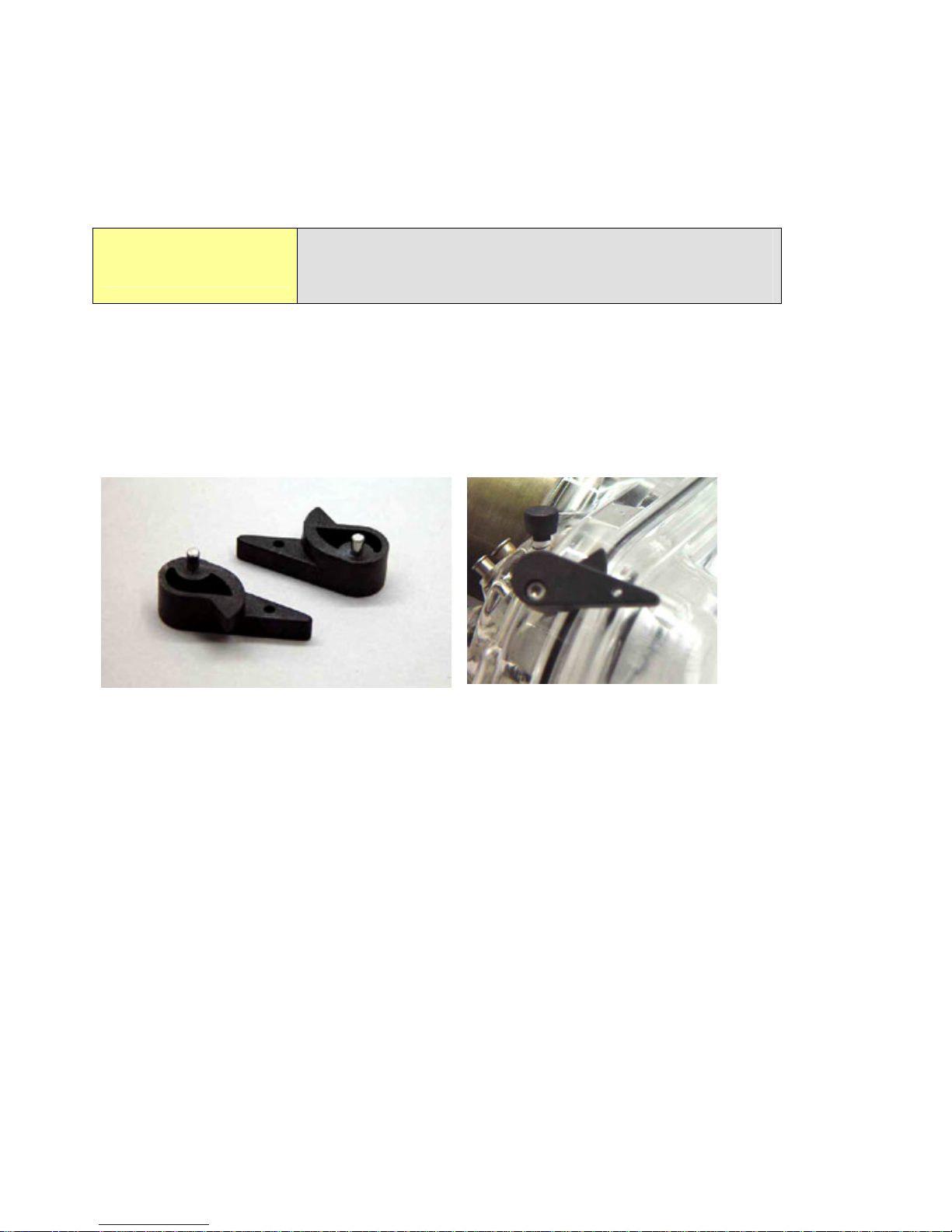
Opening Levers
After unscrewing and pulling out the pressure release plug, the lid can be opened. To overcome the
friction of opening, two levers are used to push against the lid with a cam action. On some models
these opening levers are bolted to the body. On the other models, they are detachable levers.
Be sure they are inserted all the way flat to the
Important!
The body has two holes on opposite corner edges of the housing for opening. Gently lever off the lid
with the supplied cams taking care not to twist the lid excessively. The lid should be opened keeping
it approximately parallel to the body at all times. If using a single lever, turn first one side a little, then
the other an equal amount, and repeat again until the lid is opened. Remember to unscrew and pull
out the pressure release plug all the way first, otherwise the air pressure will resist attempts at
opening. Lay the lid on a flat stable surface after opening.
housing before turning to avoid damaging the
protrusions on the lid.
Cam Levers Cam Lever in Housing
10
Page 11
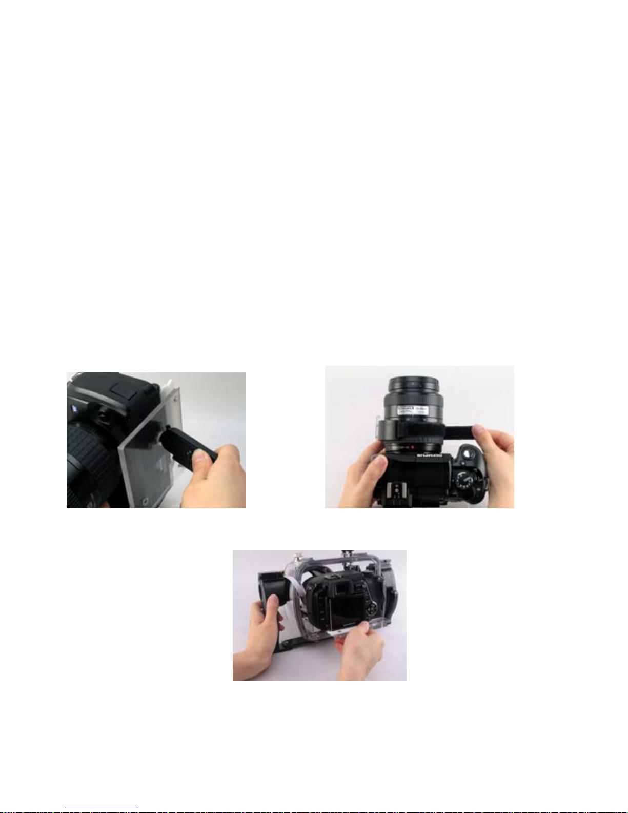
Mounting the Camera in the Housing
Remove the Lens Cap and Wrist Strap:
Make sure the camera lens to body orientation is set so the LCD screen is at top view with lens at the
extended position.
Attach the Plastic Slide Plate:
Attach the plastic slide plate to the camera's tripod mounting fixture with a coin, screw driver or the
end of the universal tool supplied [Figure 3]. Take care not to excessively tighten the screw. Secure
the zoom function guide on the lens zoom bezel [Figure 4], pointing the guide right into the slot of the
gear ring on housing bezel [Figure 5].
Attach the Zoom Control Guide Band:
Attach the Zoom Control Guide Ring to the lens. This is attached using the Velcro strip. Insure that
the projected nub is directly on the bottom.
o The Camera and tray are inserted in such a way that the nub of the
Zoom Control Guide Ring is sandwiched between the two projections
found on the lens port. All are pointed a downward direction. The Zoom
Control is operated when camera is installed in housing is this manner
using button #11
F
IGURE 3: MOUNTING PLASTIC SIDE PLATE FIGURE 4: TAPING ZOOM FUNCTION GUIDE
FIGURE 5: POINTING GUIDE INTO SLOT OF GEAR RING ON HOUSING
11
Page 12
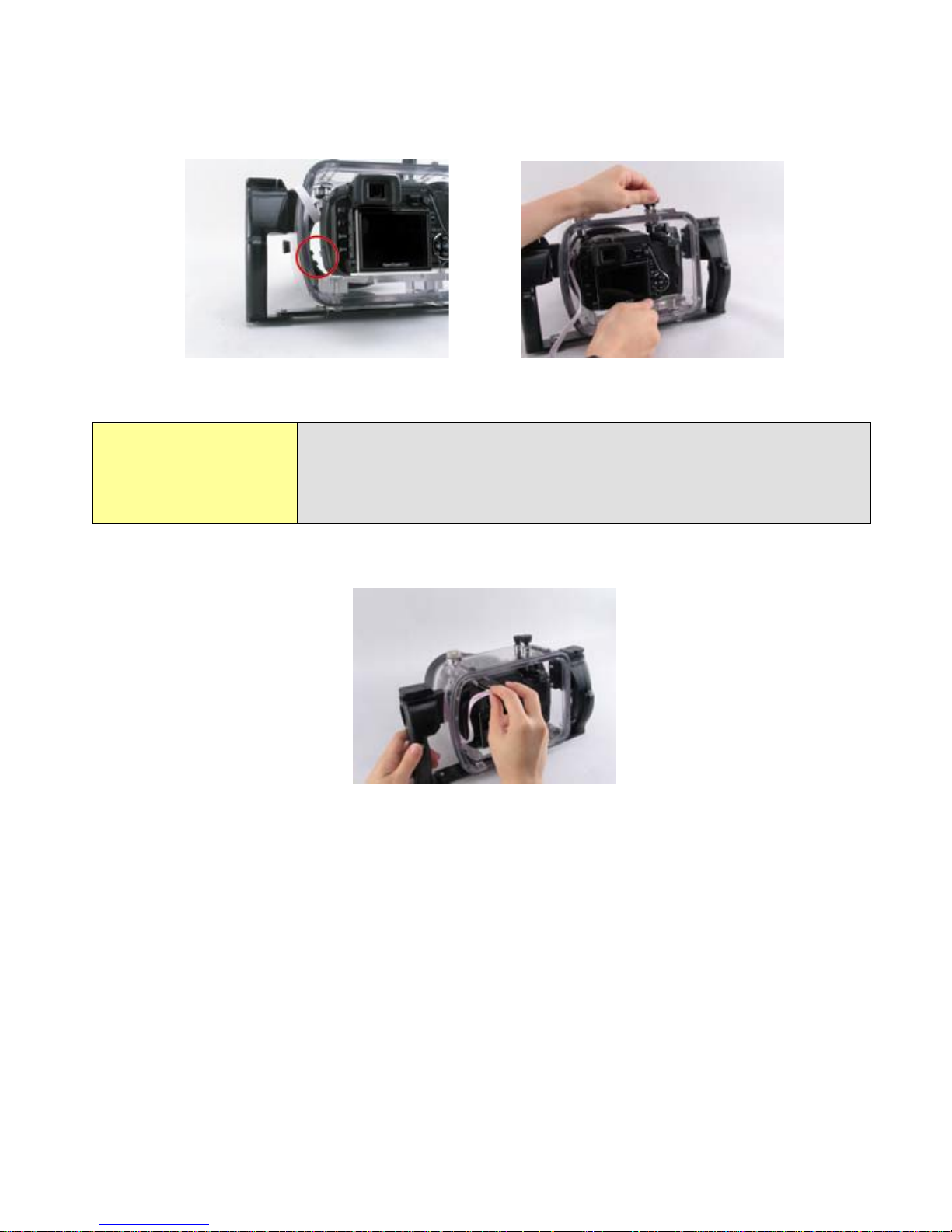
Taking up Main Dial, slide the camera into the body along the guide rail inside the bezel [Figure 6].
Make sure the camera body reaches the limit and test the function of the ON/OF BUTTONS on the body
of the housing.
IGURE 6: SLIDING CAMERA INTO BODY ALONG GUIDE RAIL [2 GRAPHICS]
F
If you find that the control levers do not articulate
properly with the camera buttons, please check again that
Note!
the camera is properly seated to the limit of the guide rail.
Never use force when placing the camera in the housing.
Slide the hot shoe insert card into the hot shoe [Figure 7].
FIGURE 7: HOT SHOE INSERT CARD INTO HOT SHOE
Close Housing
1. Place housing back over front and align the complete mating surface of the housing and
the gasket, forming a proper seal.
2. Ensure that the pressure release plug is pulled all the way out while closing, otherwise the
air cannot escape.
3. Squeeze the lid closed all the way, you will hear the hiss of air being expelled.
4. Screw home the pressure release plug; you need not excessively tighten this plug. The
seal is made by the internal O-rings. The O-ring on the underside of the plug is just to
keep out dirt and other debris. Plug is shown in Figure 8 below in the lower right hand
corner [metallic color].
12
Page 13
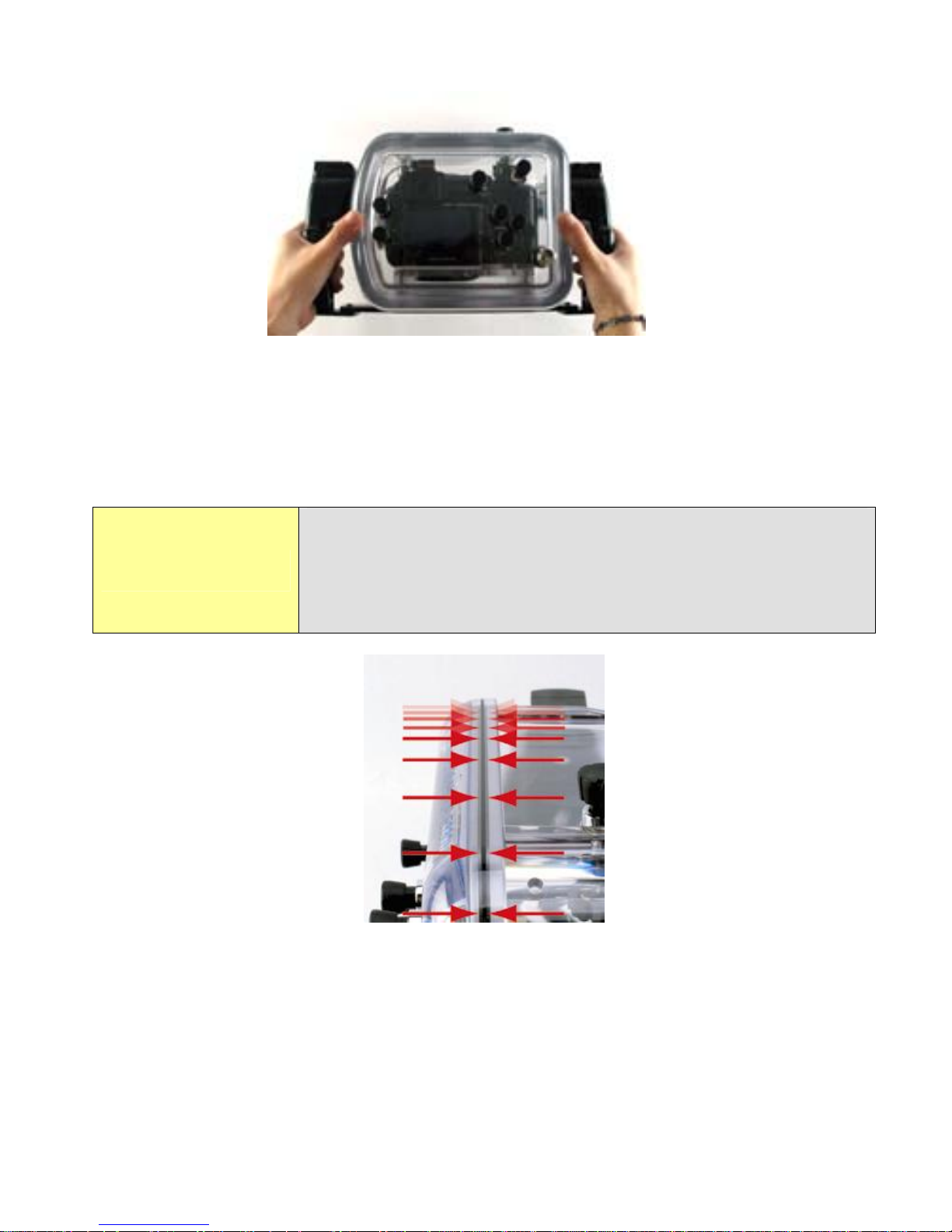
F
IGURE 8: REPLACING THE LID
5. Inspect the gasket seal for proper closure. A complete seal can be visually confirmed
by looking for the black line made by the gasket around the complete circumference of
the housing.
If the gasket is in good contact, a thin black line, about 0.51mm in width should be visible where the gasket is in
Note!
contact with the lid. Follow this line all the way round the
edge of the seal as a final check that the seal is good. The
housing is now ready for the dive.
FIGURE 9: INSPECTION OF O-RING
13
Page 14

Use & Care of Housing
Pre Dive Function Check
Just before entering the water, review the steps that you have carried out to properly close the
housing. Most importantly check that the housing is closed. Take a visual check of the gasket seal. It
is also useful to switch on the camera and check that controls e.g. ON/OFF, ZOOM and SHUTTER
functions operate normally. In case of misalignment of the camera, simply open the case and correct
the problem. Check also the battery status on the LCD display.
General Operation
The control levers and push buttons consist of internal double O-ring seals on a stainless steel shaft.
This arrangement is very reliable. As a precaution though, when operating the controls, one should
avoid excessive rapid movements, as this may cause a distortion of the O-ring. You should realize that
the camera takes a few seconds to POWER UP. If the camera does not appear to respond to a control
action, be sure that no other controls are pressing on the camera, i.e. locking out further actions. Wear
the wrist strap--it is easy to inadvertently let go of the housing, especially if you are distracted.
Cleaning & Storage
Care and Maintenance
The body and lid of the housing are made of polycarbonate. Polycarbonate was selected for its
outstanding tensile strength, hardness, toughness and its crystal clear transparency/ high gloss surface.
It has good resistance to weathering, although long-term exposure to sunlight should be avoided.
Normal operating temperature range temperature range is from 3°C to 36°C [37-97°F]--Storage
temperature: -10°C to 50°C) [14-122°F]
It is good practice to rinse off your housing with fresh water after every dive. Avoid exposure to fine
sand. After a series of 10 or more dives, e.g. after a dive holiday, it is recommended to immerse the
housing for 2-3 hours in warm water to dissolve any salt deposits that may have built up. No chemical
cleaners should be used. Mild detergents e.g. shampoo and soap based cleaners are permitted.
Polycarbonate may be harmed by some household chemicals--the
housing should never be exposed to the following classes of
Important!
FOR LONG-TERM STORAGE PLEASE REMOVE THE MAIN BODY TO LID GASKET.
chemicals:
benzene, toluene, xylene, chlorinated hydrocarbons, methanol,
any other solvents, strong acids and bases
14
Page 15

Traveling
When transporting by air, please ensure the housing is not sealed to allow the air pressure to equalize;
removing the gasket is recommended.
Please protect the housing during transportation by wrapping it in foam or other protective wrapping.
Accidents
The impact resistance of the housing is excellent. However after an accident the alignment of the
housing may have been damaged. Therefore in the event of your housing suffering an impact force,
e.g. being dropped, it is essential you do not use the housing for diving. Please return the housing
immediately for service. Please put a note inside to indicate the nature of the accident, so that we can
assess the course of action to take to renovate the housing.
Always take the first dive without your camera in the housing just to make sure
there is no leakage from damage to the housing. During the dive—especially at
Note!
the beginning of descent—take special care to look at the housing to make sure
no bubbles are escaping from it and that no water is entering. Generally, if there
is a problem with the seal, you will discover it in the first seconds of the dive.
Service
It is recommended to have annual maintenance of all Fantasea housings. It is likewise recommended
to use an authorized Fantasea Service Center for this purpose. Please contact Fantasea Line by email:
[email protected] or visit the Fantasea Customer Service section on the web site
www.fantasea.com. To ensure the continued performance of your housing, it should be serviced
every year, or after every 200 dives. Please note the terms for servicing the housing posted at our
website. A full service will include:
• Inspection of all components for wears or damage (report if repair
necessary)
• Cleaning of all sealing surfaces, and replacement of all gasket seals.
• Hydrostatic pressure test
Note: the replacement of damaged components (except replacement gasket) may require additional
cost.
15
Page 16

Warranty
The FE 330 includes a one-year limited warranty for defective parts which the manufacturer will
replace.
See separate insert page regarding the unique FE 330 anti flooding program by DEPP and the FE 330
Accessory Products page.
16
 Loading...