

FANOX SIA-C User Manual
Sia_Manu_Siac_Ing_R026
USER´S MANUAL
SIA-C
Dual & Self powered overcurrent & earth fault relay

www.fanox.com Rev. 26 2/188
1. RECEPTION, HANDLING, INSTALLATION ..................................................... 6
1.1. Unpacking ................................................................................................................................. 6
1.2. Reception of relays .................................................................................................................. 6
1.3. Handling electronic equipment ............................................................................................... 6
1.4. Installation, commissioning and service ............................................................................... 7
1.5. Storage ...................................................................................................................................... 7
1.6. Recycling ................................................................................................................................... 7
2. DIMENSIONS AND CONNECTION DIAGRAMS .............................................. 8
2.1. Case Dimensions mm of SIA-C with mechanics type A ....................................................... 8
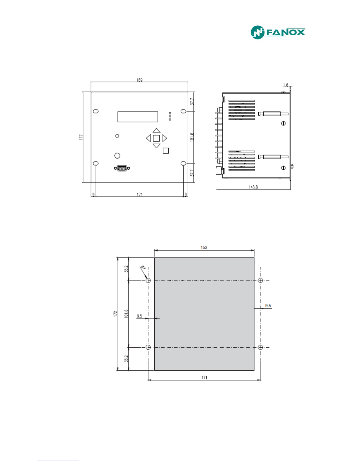
2.2. Case Dimensions mm of SIA-C with mechanics type B and C .......................................... 10
2.3. Case Dimensions mm of SIA-C with mechanics type D ..................................................... 12
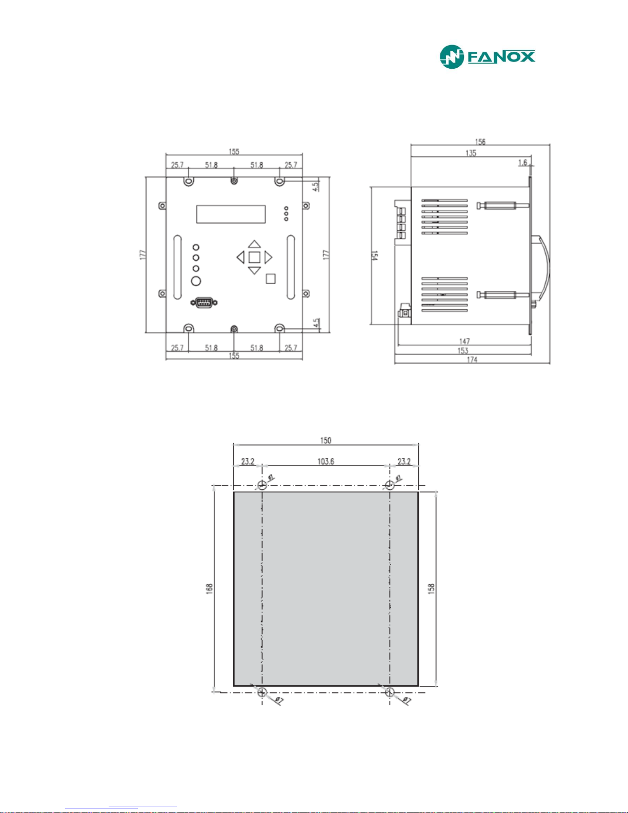
2.4. Case Dimensions mm of SIA-C with mechanics type E and G .......................................... 13
2.5. Case Dimensions mm of SIA-C with mechanics type F (withdrawable) ........................... 14
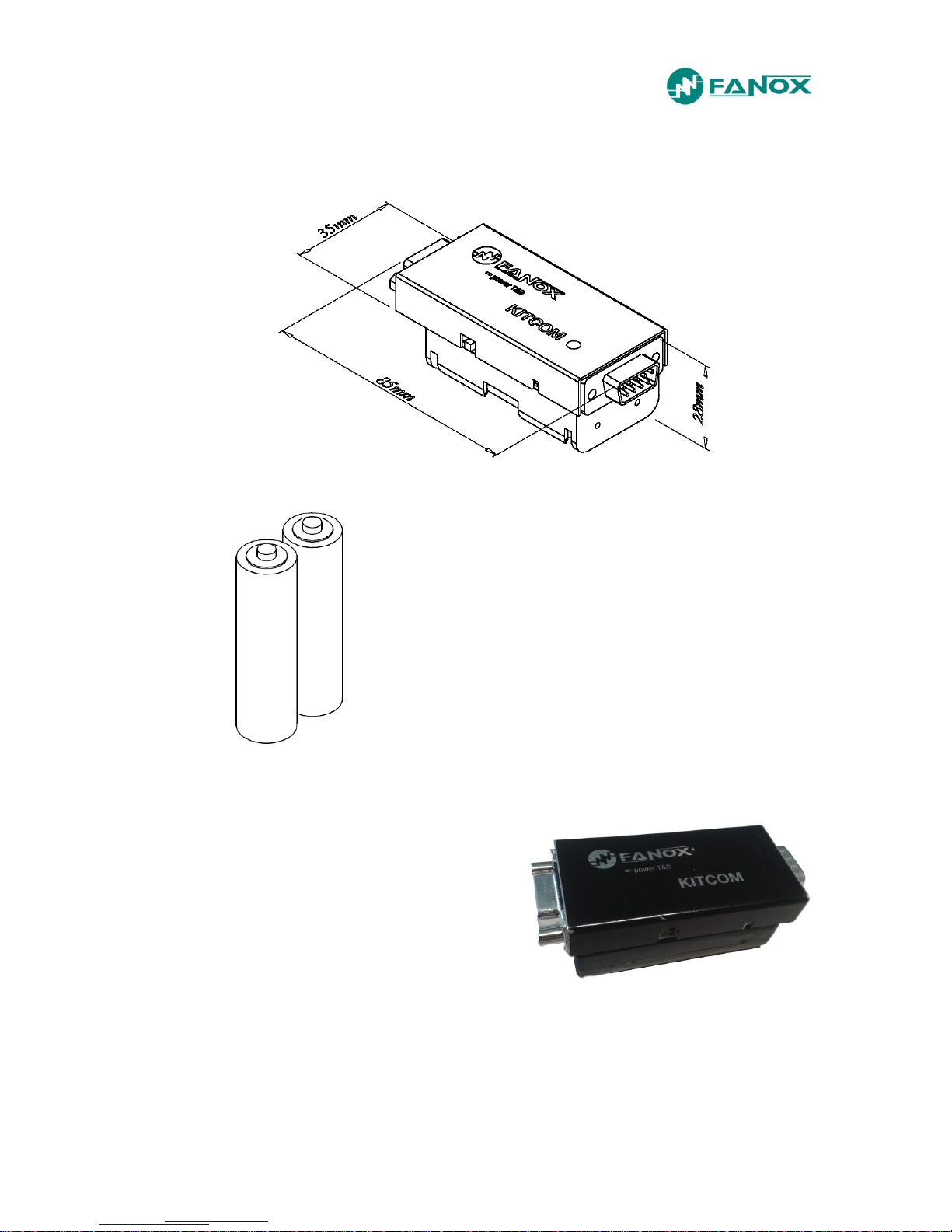
2.6. KITCOM Dimensions .............................................................................................................. 15
2.7. Striker Dimensions (in mm) ................................................................................................... 16
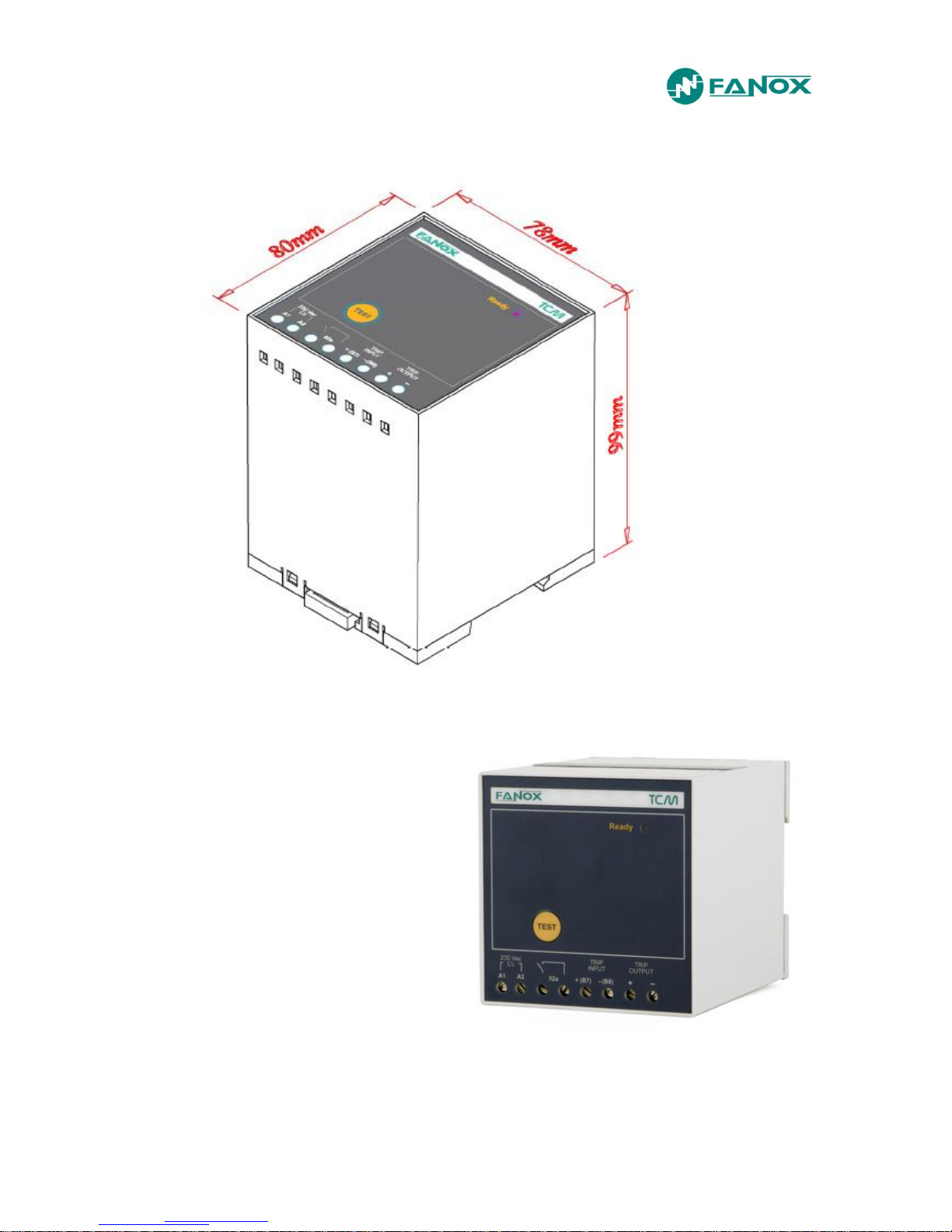
2.8. TCM Dimensions .................................................................................................................... 17
2.9. Connection diagrams ............................................................................................................. 18
2.9.1. Separated terminals connectors for measurement and power supply ................................. 18
2.9.2. Simple terminals connector (measurement and power supply)............................................ 32
2.10. Terminals ............................................................................................................................. 38
2.10.1. Physical layout of SIA-C type A and D terminals .............................................................. 38
2.10.2. Physical layout of SIA-C types B and C terminals ............................................................ 42
2.10.3. Physical layout of SIA-C type E terminals ......................................................................... 46
2.10.4. Physical layout of SIA-C type F terminals (withdrawable model) ..................................... 50
2.10.5. Physical layout of SIA-C type G terminals ........................................................................ 51
3. DESCRIPTION ................................................................................................. 52
3.1. Introduction ............................................................................................................................. 52
3.2. Description .............................................................................................................................. 52
3.3. Functional Diagram ................................................................................................................ 57
3.4. Selection & Ordering data ..................................................................................................... 58
3.5. Phase CT and neutral CT selection ...................................................................................... 59
3.5.1. Load curve for relay SIA-C/1................................................................................................. 60
3.5.2. Load curve for relay SIA-C/5................................................................................................. 60
4. PROTECTION FUNCTIONS ............................................................................ 61
4.1. General settings ..................................................................................................................... 61
4.2. 50P Function . Phase instantaneous overcurrent ............................................................... 61
4.3. 50/51P Function. Phase inverse time overcurrent .............................................................. 62
4.4. 50N/G Function. Neutral instantaneous overcurrent. ......................................................... 62

www.fanox.com Rev. 26 3/188
4.5. 50/51N/G Function. Neutral inverse time overcurrent. ....................................................... 63
4.6. Function CLP. Cold Load Pickup .......................................................................................... 63
4.7. External trip ............................................................................................................................. 65
4.8. Function 68. Trip bus protection function ........................................................................... 65
4.9. Protection Settings ................................................................................................................. 70
4.10. Settings table ...................................................................................................................... 72
4.11. IEC60255-151 Curves .......................................................................................................... 73
4.12. ANSI-IEEE Curves ............................................................................................................... 78
4.13. Application examples ......................................................................................................... 82
5. MONITORING AND CONTROL ...................................................................... 88
5.1. Measurements ........................................................................................................................ 88
5.2. Demand.................................................................................................................................... 88
5.3. Status and Events .................................................................................................................. 89
5.4. Fault reports ............................................................................................................................ 97
5.5. Self-diagnosis ......................................................................................................................... 98
5.6. Date-time synchronisation .................................................................................................... 98
5.7. Digital inputs ........................................................................................................................... 99
5.8. Digital Outputs ........................................................................................................................ 99
5.9. Programmable Logic Control & Digital Outputs ............................................................... 100
5.10. 86 Function. Trip Output Lockout ................................................................................... 103
5.11. Test program ..................................................................................................................... 103
5.12. Power supply ..................................................................................................................... 105
5.12.1. Self Power: CT-5 A or CT-1 A, 0,2 x In rated in single phase ........................................ 105
5.12.2. Battery power: 12V, with a KITCOM adaptor .................................................................. 105
5.12.3. 230 Vac or 110 Vac, 50/60 Hz auxiliary power ............................................................... 107
5.12.4. 24 Vdc or 48 Vdc auxiliary power supply ........................................................................ 108
5.13. Equipment starting up time. Fault trip time during starting up of the equipment. .... 108
5.13.1. SIA-C for striker ............................................................................................................... 109
5.13.2. SIA-C withdrawable model .............................................................................................. 111
5.13.3. SIA-C for coil ................................................................................................................... 113
5.14. Opening mechanism ......................................................................................................... 115
5.14.1. Striker activation .............................................................................................................. 116
5.14.2. Coil activation by means of a free potential contact ........................................................ 117
5.14.3. Coil activation by means of TCM adapter ....................................................................... 117
6. TECHNICAL SPECIFICATIONS AND STANDARDS ................................... 118
6.1. Technical Specifications...................................................................................................... 118
6.2. Thermal resistance ............................................................................................................... 121
6.3. Standards .............................................................................................................................. 121

www.fanox.com Rev. 26 4/188
7. COMMUNICATION AND HMI ........................................................................ 125
7.1. Communication .................................................................................................................... 125
7.2. Front communication. RS232 .............................................................................................. 125
7.3. Rear communication. RS485 ............................................................................................... 125
7.4. Bistable magnetic indicators .............................................................................................. 127
7.5. LED Indicators ...................................................................................................................... 128
7.6. LCD and keypad ................................................................................................................... 131
7.7. SICom communications program ....................................................................................... 131
7.7.1. How to install SICOM Software .......................................................................................... 132
7.8. Setting-up the session: Password and access levels ...................................................... 133
7.9. Menus .................................................................................................................................... 134
7.9.1. Standby mode screen ......................................................................................................... 134
7.9.2. Accessing the menus .......................................................................................................... 134
7.9.3. Date-time menu .................................................................................................................. 135
7.9.4. Versions .............................................................................................................................. 135
7.9.5. Communication parameters ................................................................................................ 135
7.9.6. Contrast............................................................................................................................... 136
7.9.7. Test menu ........................................................................................................................... 137
7.9.8. Functions menu .................................................................................................................. 143
7.9.9. Measurements menu .......................................................................................................... 145
7.9.10. Status menu .................................................................................................................... 146
7.9.11. Settings menu ................................................................................................................. 157
7.9.12. Events menu ................................................................................................................... 163
7.9.13. Demand menu ................................................................................................................. 165
7.9.14. Fault reports .................................................................................................................... 166
7.9.15. PLC and Output Configuration Menu .............................................................................. 167
8. MODBUS RTU PROTOCOL .......................................................................... 171
8.1. ModBus package format ...................................................................................................... 172
8.2. Function codes ..................................................................................................................... 172
8.3. Exemptions an error answers ............................................................................................. 173
8.4. Data type................................................................................................................................ 173
8.5. Memory map of SIA-C .......................................................................................................... 174
8.6. Counters Map ........................................................................................................................ 178
8.7. Commands Map .................................................................................................................... 178
8.8. Examples of ModBus frames .............................................................................................. 179
8.8.1. Writing the access password “5555” to equipment no. 1 .................................................... 179
9. COMMISSIONING ......................................................................................... 180
9.1. Checklist for commissioning .............................................................................................. 180

www.fanox.com Rev. 26 5/188
9.2. Inspection .............................................................................................................................. 180
9.3. Electrostatic discharge ........................................................................................................ 180
9.4. Visual inspection .................................................................................................................. 180
9.5. Earthing ................................................................................................................................. 180
9.6. Current transformers ........................................................................................................... 180
9.7. Auxiliary power ..................................................................................................................... 180
9.8. RS232 Front communications port ..................................................................................... 181
9.9. Commissioning ..................................................................................................................... 181
10. APPENDIX ..................................................................................................... 182
10.1. Identification ...................................................................................................................... 182
10.2. Checks ............................................................................................................................... 183
10.3. Test menu .......................................................................................................................... 183
10.4. Register of commissioning settings ............................................................................... 183
10.5. Inputs ................................................................................................................................. 185
10.6. Outputs .............................................................................................................................. 185
10.7. Leds .................................................................................................................................... 185
10.8. Comments ......................................................................................................................... 186

www.fanox.com Rev. 26 6/188
1. RECEPTION, HANDLING, INSTALLATION
1.1. Unpacking
Relays must only be handled by qualified personnel and special care must be taken to protect
all of their parts from any damage while they are being unpacked and installed. The use of
good illumination is recommended to facilitate the equipment visual inspection. The facility must
be clean and dry and relays should not be stored in places that are exposed to dust or humidity.
Special care must be taken if construction work is taking place.
1.2. Reception of relays
It is necessary to inspect the equipment at the time it is delivered to ensure that the relays have
not been damaged during transport.
If any defect is found, the transport company and FANOX should be informed immediately.
If the relays are not for immediate use, they should be returned to their original packaging.
1.3. Handling electronic equipment
Relays contain an electronic component that is sensitive to electrostatic discharges.
Just by moving, a person can build up an electrostatic potential of several thousand volts.
Discharging this energy into electronic components can cause serious damage to electronic
circuits. It is possible that this damage may not be detected straight away, but the electronic
circuit reliability and life will be reduced. This electronic component in the equipment is well
protected by the metal housing, which should not be removed as the equipment cannot be
adjusted internally.
If it is necessary to disassemble the electronic component, this must be carried out with care
and contact with electronic components, printed circuits and connections must be avoided to
prevent an electrostatic discharge that could damage one of the components. If the electronic
components are stored outside the metal housing, they must be placed in an antistatic
conductive bag.
If it is necessary to open a module, care must be taken to preserve the equipment reliability and
the duration of the life cycle as designed by the manufacturer by taking the following actions:
Touch the housing to ensure that you have the same potential
Avoid touching the electronic components and handle the module by its edges.
Remember that everyone who handles the module must have the same potential.
Use a conductive bag to transport the module.
For more information about how to handle electronic circuits, consult official documents such as
the IEC 147-OF.

www.fanox.com Rev. 26 7/188
1.4. Installation, commissioning and service
The personnel in charge of installing, commissioning and maintaining this equipment must be
qualified and must be aware of the procedures for handling it. The product documentation
should be read before installing, commissioning or carrying out maintenance work on the
equipment.
Personnel should take specific protection measures to avoid the risk of electronic discharge
when access is unlocked on the rear part of the equipment.
In order to guarantee safety, the crimp terminal and a suitable tool must be used to meet
isolation requirements on the terminal strip. Crimped terminations must be used for the voltage
and current connections.
It is necessary to connect the equipment to earth through the corresponding terminal, using the
shortest possible cable. As well as guaranteeing safety for the personnel, this connection
allows high frequency noise to be evacuated directly to earth.
The following checks must be performed before the equipment is supplied:
The rated voltage and polarity.
The power rating of the CT circuit and the integrity of the connections.
The integrity of the earth connection.
The equipment must be used within the stipulated electrical and environmental limits.
Note referred to current transformer circuits: Do not open a live CT secondary circuit. The high
voltage produced as a result could damage the isolation and threaten lives.
1.5. Storage
If the relays are not going to be installed immediately, they must be stored in a dust- and
humidity free environment after the visual inspection has been performed.
1.6. Recycling
Before recycling the equipment, the capacitors should be discharged through the external
terminals. All electrical power sources should be removed before performing this operation to
avoid the risk of electrical discharge.
This product must be disposed of in a safe way. It should not be incinerated or brought into
contact with water sources like rivers, lakes, etc…
www.fanox.com Rev. 26 8/188
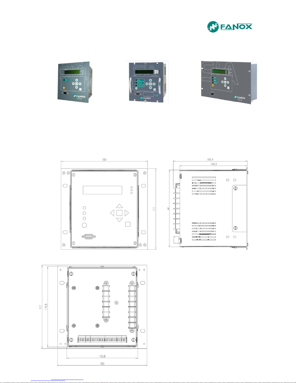
2. DIMENSIONS AND CONNECTION DIAGRAMS
Vertical assembly Withdrawable Vertical assembly Horizontal assembly
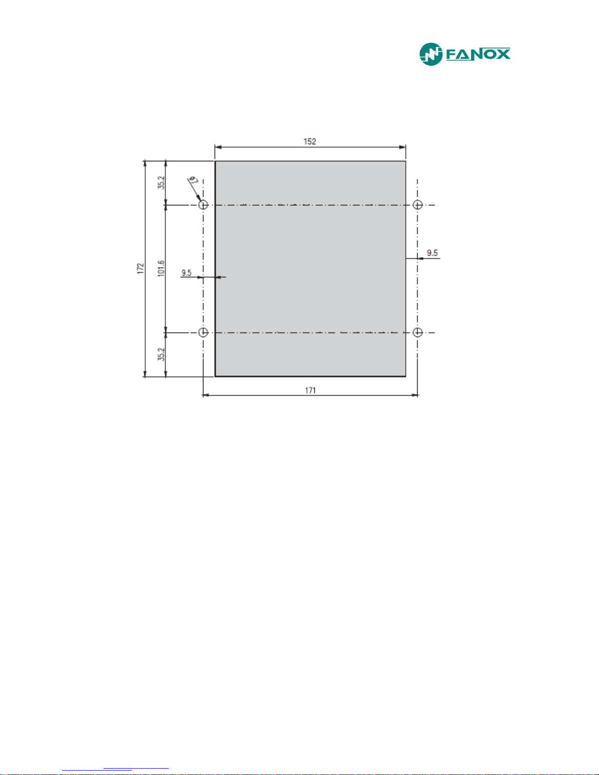
2.1. Case Dimensions mm of SIA-C with mechanics type A
www.fanox.com Rev. 26 9/188
Cut-out pattern
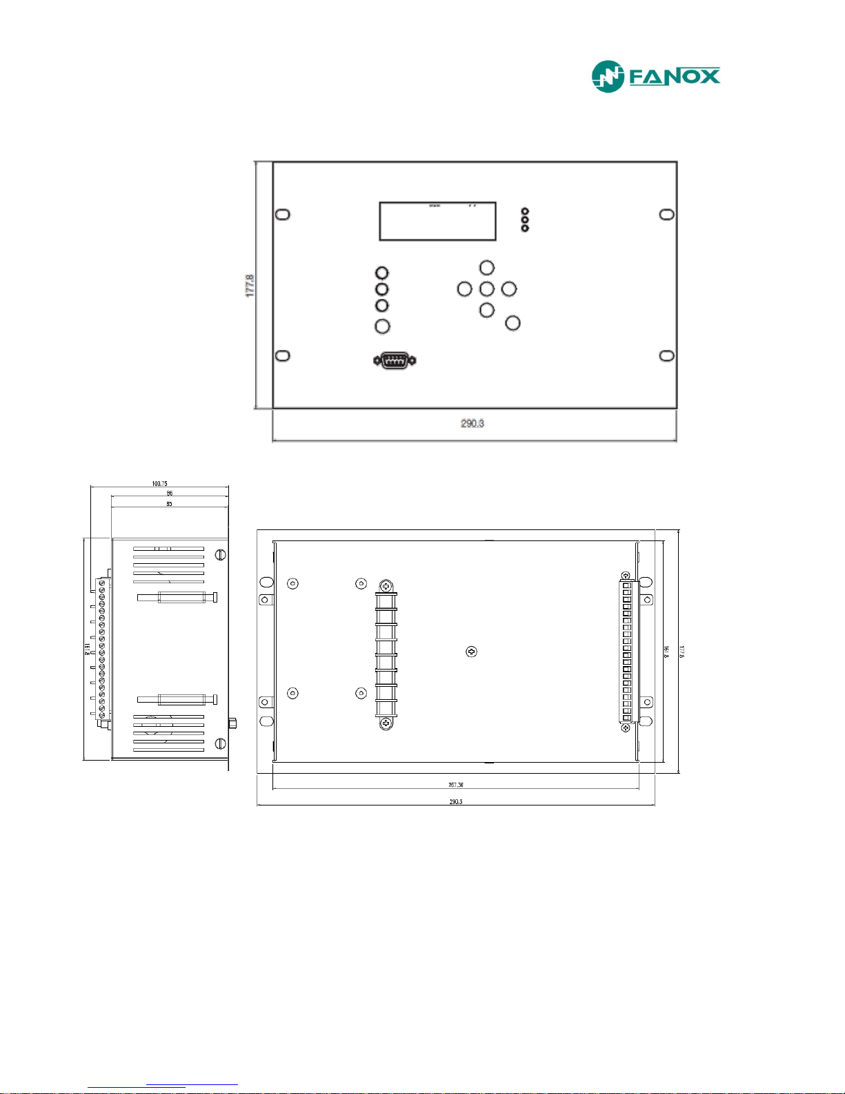
www.fanox.com Rev. 26 10/188
2.2. Case Dimensions mm of SIA-C with mechanics type B and C

www.fanox.com Rev. 26 11/188
Cut-out pattern
www.fanox.com Rev. 26 12/188
2.3. Case Dimensions mm of SIA-C with mechanics type D
Cut-out pattern

www.fanox.com Rev. 26 13/188
2.4. Case Dimensions mm of SIA-C with mechanics type E and G
Cut-out pattern
www.fanox.com Rev. 26 14/188
2.5. Case Dimensions mm of SIA-C with mechanics type F (withdrawable)
Cut-out pattern
www.fanox.com Rev. 26 15/188
2.6. KITCOM Dimensions

www.fanox.com Rev. 26 16/188
2.7. Striker Dimensions (in mm)
A
44,5
B
49,5 C 56,5
D
64,5 E 42,5
www.fanox.com Rev. 26 17/188
2.8. TCM Dimensions
www.fanox.com Rev. 26 18/188
2.9. Connection diagrams
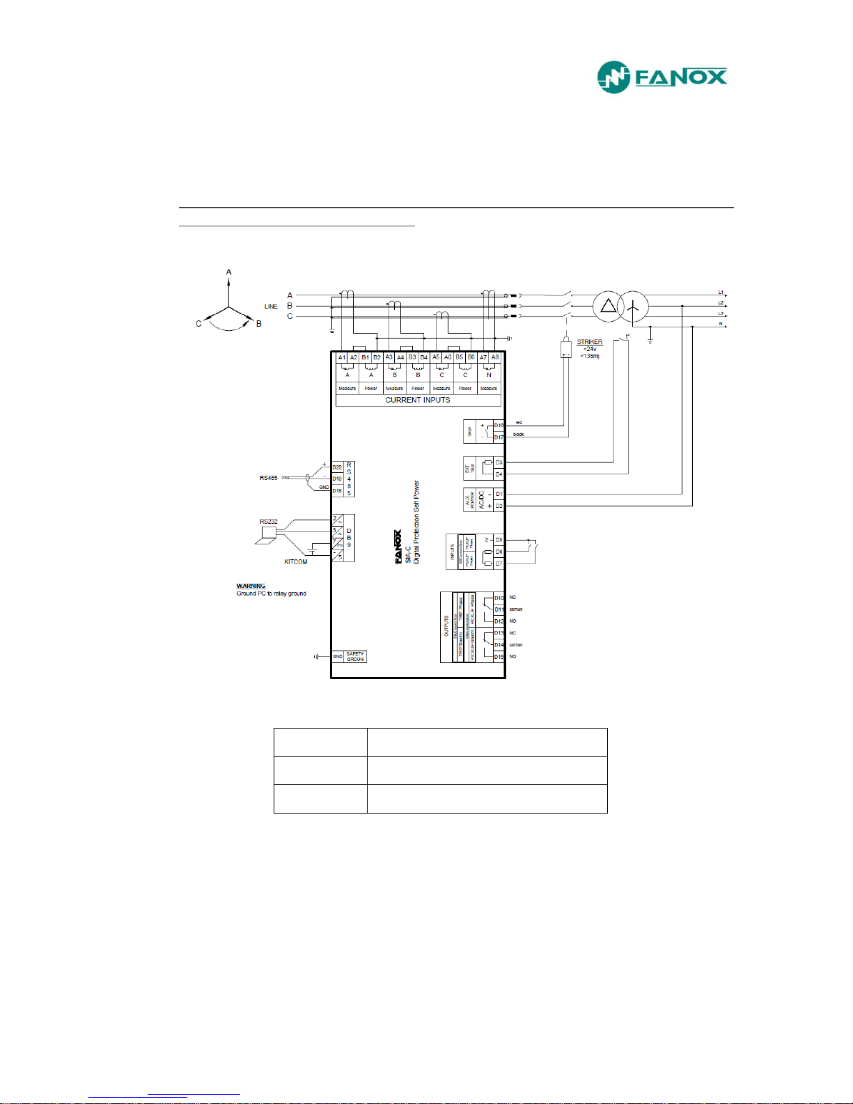
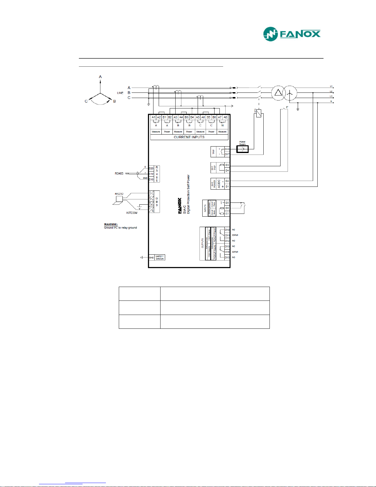
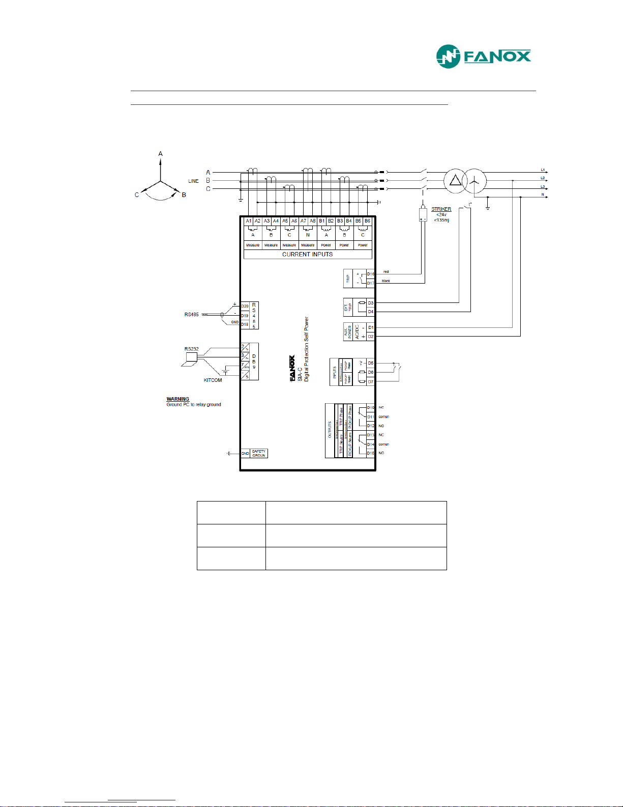
2.9.1. Separated terminals connectors for measurement and power supply
Connection diagram. 3 phase transformers: Power Supply and Measurement
– Sensitive Neutral – Trip: Striker
Neutral
Sensitive Neutral
Trip
Striker
Supply
230Vac (depending on model)
www.fanox.com Rev. 26 19/188
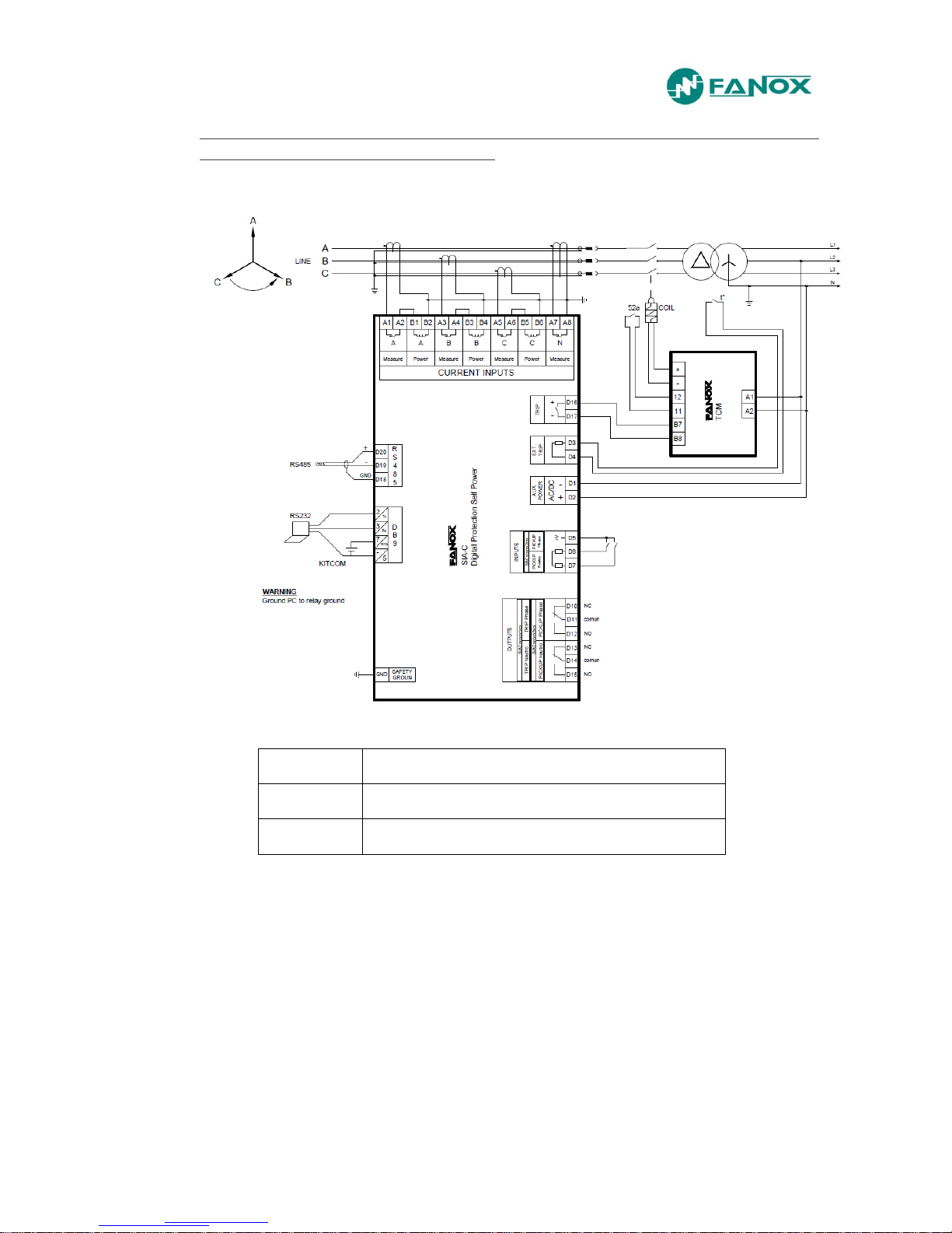
Connection diagram. 3 phase transformers: Power Supply and Measurement
– Sensitive Neutral – Trip: Coil + TCM
Neutral
Sensitive Neutral
Trip
Striker + TCM
Supply
230Vac (depending on model)
www.fanox.com Rev. 26 20/188
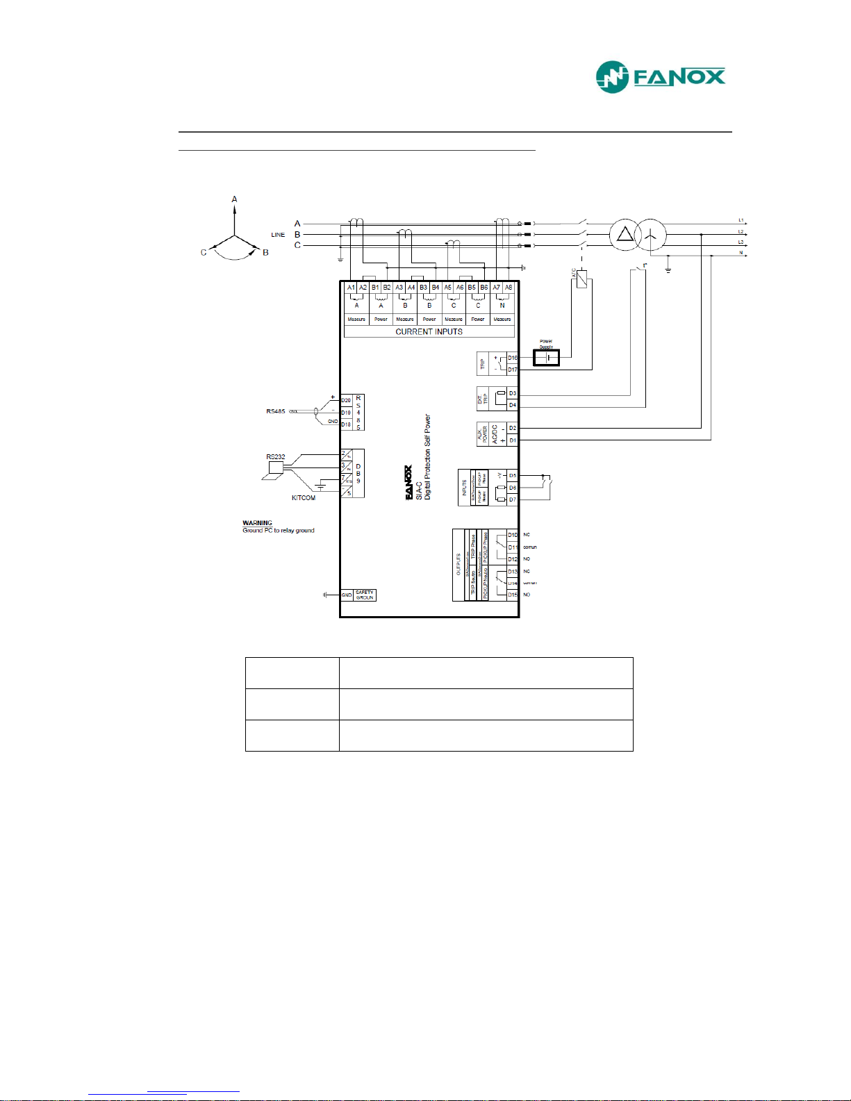
Connection diagram. 3 phase transformers: Power Supply and Measurement
– Sensitive Neutral – Trip: ATC (free potential trip)
Neutral
Sensitive Neutral
Trip
ATC
Supply
230Vac (depending on model)
www.fanox.com Rev. 26 21/188
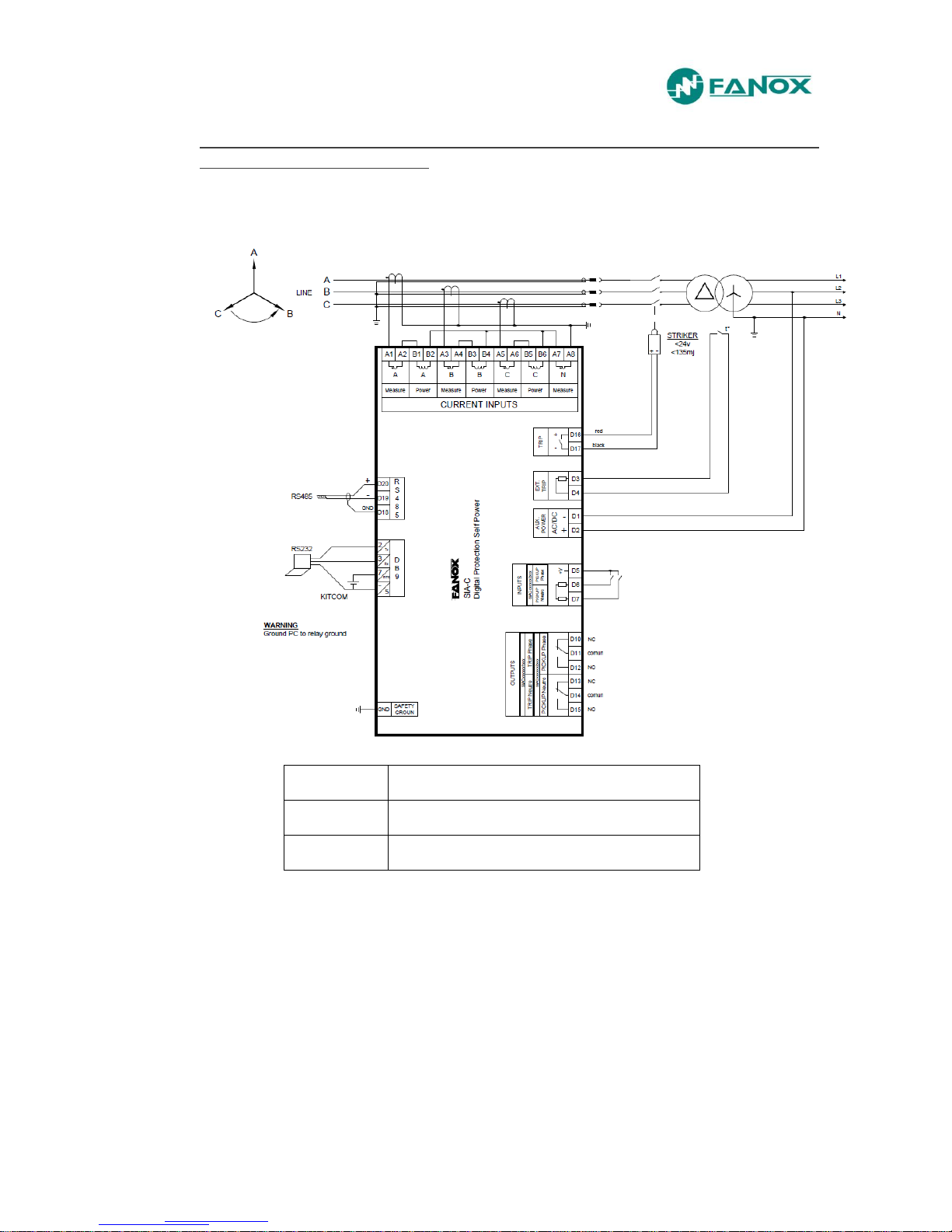
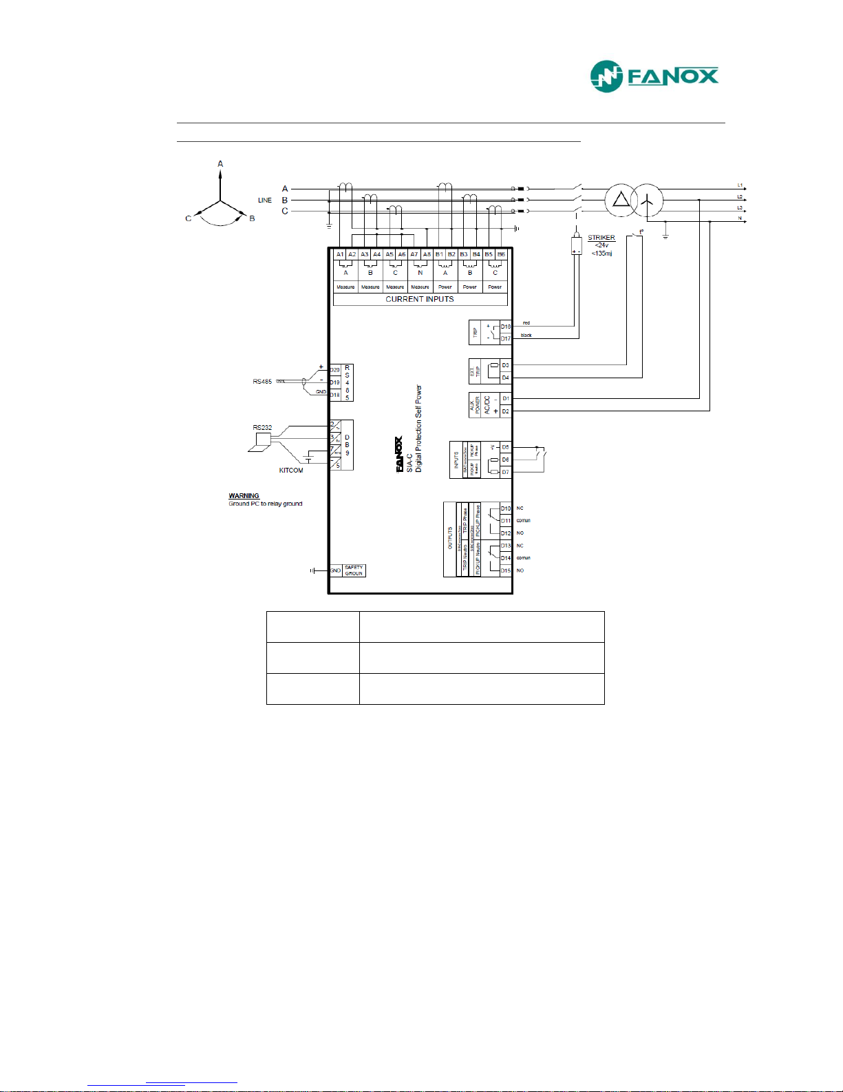
Connection diagram. 3 phase transformers: Power Supply and Measurement
– Solid Neutral – Trip: Striker
Neutral
Solid neutral
Trip
Striker
Supply
230Vac (depending on model)

www.fanox.com Rev. 26 22/188
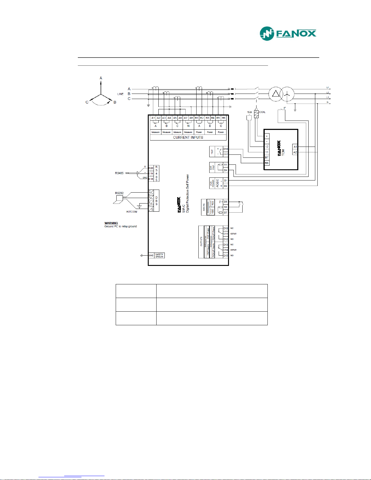
Connection diagram. 3 phase transformers: Power Supply and Measurement
– Solid Neutral – Trip: Coil + TCM
Neutral
Solid neutral
Trip
TCM
Supply
230Vac (depending on model)
www.fanox.com Rev. 26 23/188
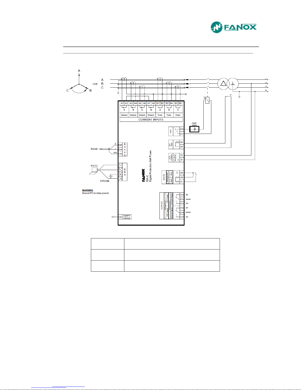
Connection diagram. 3 phase transformers: Power Supply and Measurement
– Solid Neutral – Trip: ATC (free potential trip)
Neutral
Solid neutral
Trip
ATC
Supply
230Vac (depending on model)
www.fanox.com Rev. 26 24/188
Connection diagram. 3 phase transformers: Power Supply – 3 phase
transformers: Measurement – Solid Neutral – Trip: Striker
Neutral
Solid neutral
Trip
Striker
Supply
230Vac (depending on model)
www.fanox.com Rev. 26 25/188
Connection diagram. 3 phase transformers: Power Supply – 3 phase
transformers: Measurement – Solid Neutral – Trip: Coil + TCM
Neutral
Solid neutral
Trip
TCM
Supply
230Vac (depending on model)
www.fanox.com Rev. 26 26/188
Connection diagram. 3 phase transformers: Power Supply – 3 phase
transformers: Measurement – Solid Neutral – Trip: ATC (Potential Free Trip)
Neutral
Solid neutral
Trip
ATC
Supply
230Vac (depending on model)
www.fanox.com Rev. 26 27/188
Connection diagram. 3 phase transformers: Power Supply – 3 phase
transformers: Measurement – Sensible Neutral – Trip: Striker
Neutral
Sensible neutral
Trip
Striker
Supply
230Vac (depending on model)
(*) For trip: Trip: Coil + TCM and trip: ATC, the same as in previous examples
www.fanox.com Rev. 26 28/188
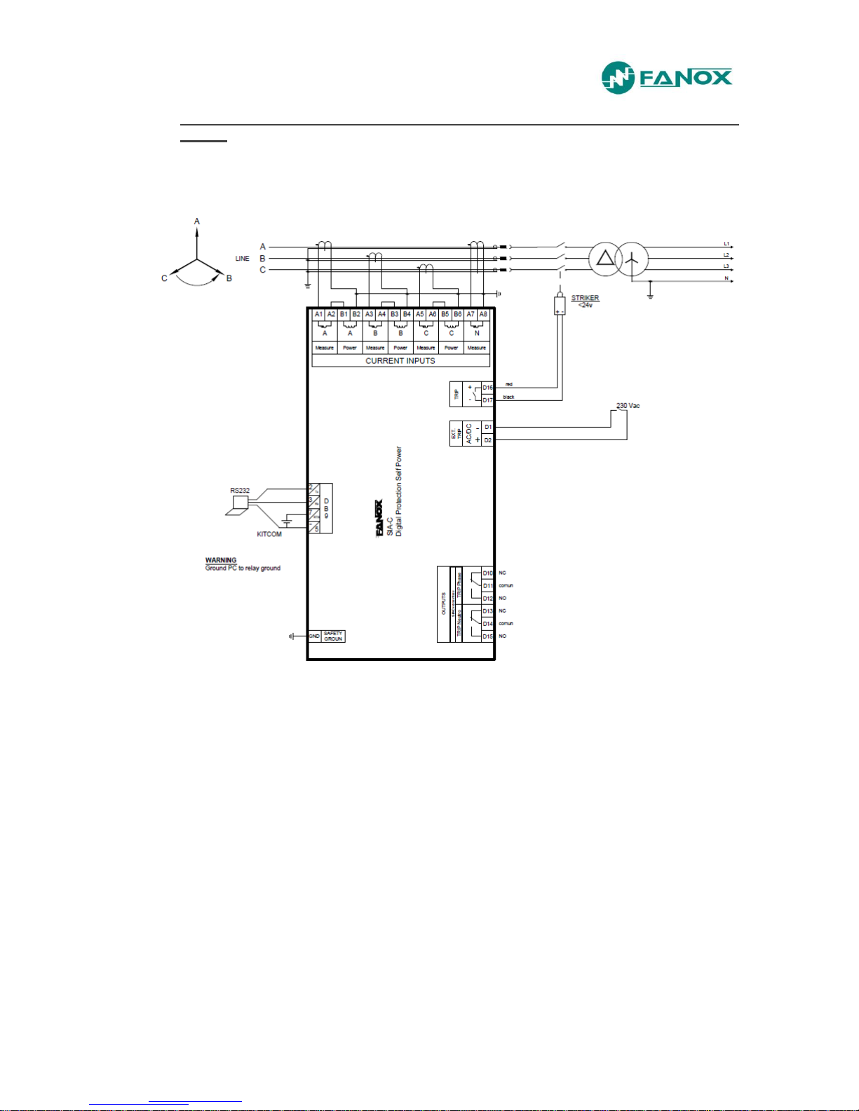
In SIACxxxx4xxxxx, external trip is at 230 Vac. Connection diagrams are as
follow:
3 phase transformers: Power supply and measurement - sensible neutral:
www.fanox.com Rev. 26 29/188
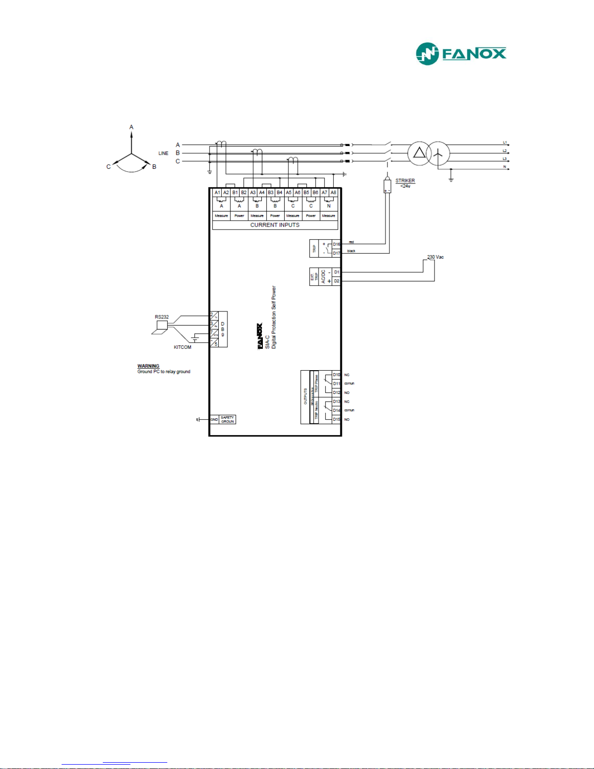
3 phase transformers: Power supply and measurement - solid neutral
www.fanox.com Rev. 26 30/188
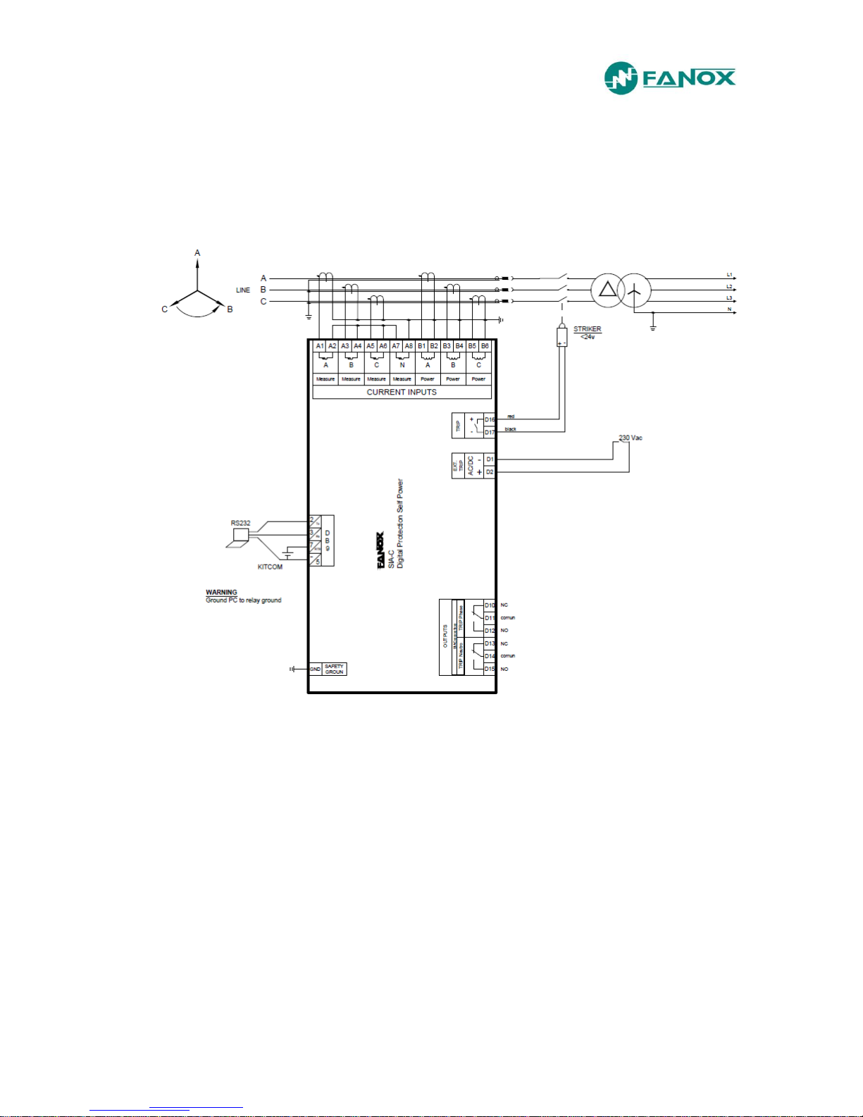
3 phase transformers: Measurement, 3 phase transformer: Power supply - solid
neutral
 Loading...