

FANOX SIA-B, SIAB000B0010AA Installation & Commissioning Manual

INSTALLATION & COMMISSIONING GUIDE
SIA-B
Self & Dual Power
Overcurrent Protection
Relay

www.fanox.com Installation_Guide_SIAB000B0010AA_Rev. 03 2 / 32
1. ..... RECEPTION & INSTALLATION .......................................................................................... 3
1.1. Relay unpacking ............................................................................................................. 3
1.2. Relay verification ............................................................................................................ 3
1.3. Powering the relay up .................................................................................................... 4
1.4. Relay intallation .............................................................................................................. 6
1.5. Relay rear part ................................................................................................................ 7
1.6. Connection diagram ....................................................................................................... 7
2. ..... USER INTERFACE .............................................................................................................. 8
2.1. Relay front part ............................................................................................................... 8
2.2. Bistable magnetic indicator (Flag) ............................................................................... 8
2.3. LED indicators ................................................................................................................ 8
2.4. How to install SICOMM software .................................................................................. 8
2.5. Setting-up the session: Password and access levels ................................................ 9
3. ..... FUNCTIONAL DIAGRAM .................................................................................................... 9
4. ..... TECHNICAL SPECIFICATIONS ........................................................................................ 10
4.1. IEC60255-151 Curves ................................................................................................... 12
4.2. IEEE Curves .................................................................................................................. 12
5. ..... SPECIFIC CURRENT TRANSFORMERS ......................................................................... 13
5.1. Test Winding ................................................................................................................. 14
6. ..... OPENING MECHANISM .................................................................................................... 14
7. ..... FLOWCHART ..................................................................................................................... 15
7.1. Test menu...................................................................................................................... 15
7.2. Direct Access ................................................................................................................ 15
7.3. Menus ............................................................................................................................ 17
8. ..... COMMISIONING ................................................................................................................ 23
8.1. Thermal resistance ....................................................................................................... 23
8.2. Self powering ................................................................................................................ 25
8.3. Measurements .............................................................................................................. 26
8.4. Protection functions .................................................................................................... 26
9. ..... SIAB000B0010AA REGISTRY .......................................................................................... 30
www.fanox.com Installation_Guide_SIAB000B0010AA_Rev. 03 3 / 32
1. RECEPTION & INSTALLATION
1.1. Relay unpacking
Previously to any handling action, confirm that relay carton box is in good conditions, no broken
or damaged due to external manipulation or during storing or moving process. If packing is
correct, proceed to unpack and you should find following element:
• SIAB Electronic protection relay.
• User Guide.
• Testing protocol.
Testing protocol is a certificate that relay has passed all factory testing process with correct
results.
In case some fault is detected, consider putting into quarantine period the relay and contact
Fanox for further instructions.
1.2. Relay verification
When relay is unpacked, please, take your time to confirm following checking list to be sure that
everything is ok:
• Metallic case not damaged and well assembled. No loose screws due to transport or
movement conditions
• LCD and front cover not damaged or scratched.
• Quality sticker and terminal sticker correctly stuck.
• Rear terminals in good state, being able to do a good wiring connection.
www.fanox.com Installation_Guide_SIAB000B0010AA_Rev. 03 4 / 32
1.3. Powering the relay up
Thanks to the external battery KITCOM the powering and adjusting process of the relay is very
easy and it allows the user to test the relay.
The power comes from two AA batteries (IEC LR06) of 1.5 Volts placed at the bottom of the
kitcom. The equipment has a small Dc/Dc power supply that raises the voltage till the required 5
volts to operate the equipment and that is plugged into the front USB communications port
(KITCOM).
Once the KITCom is connected, the relay will be switched on and a led on the left of the relay
(led on) will blink indicating the relay is powered on through an external battery (KITCOM).
The relay is totally maintenance free. This is, there is no need of batteries to log events and
fault reports and there is no need of batteries to maintain date and time.
NOTE: Date and time must be correctly set the first time the relay is operative and energy
must be kept at least “1 hour” to maintain the RTC for 72 hours once the energy is lost.
Besides, the possibility of using external battery power, together with the possibility of activating
the trip contact from the test menu, allows the trip circuit to be tested before the transformation
center is powered up. So, the KITCOM is useful for cases like commissioning operations,
discharges and repairs to the transformation center.
Using battery power does not block the USB communications port, as it can be used
simultaneously.
Once the relay is powered through the Kitcom, it should be checked:
• Model Directly, complete model on top line and phases/neutral current
measurement on bottom line are displayed. Once “C” key is pressed the name of phase
and neutral currents (instead the complete model) is displayed on the top of LCD
Standby screen.
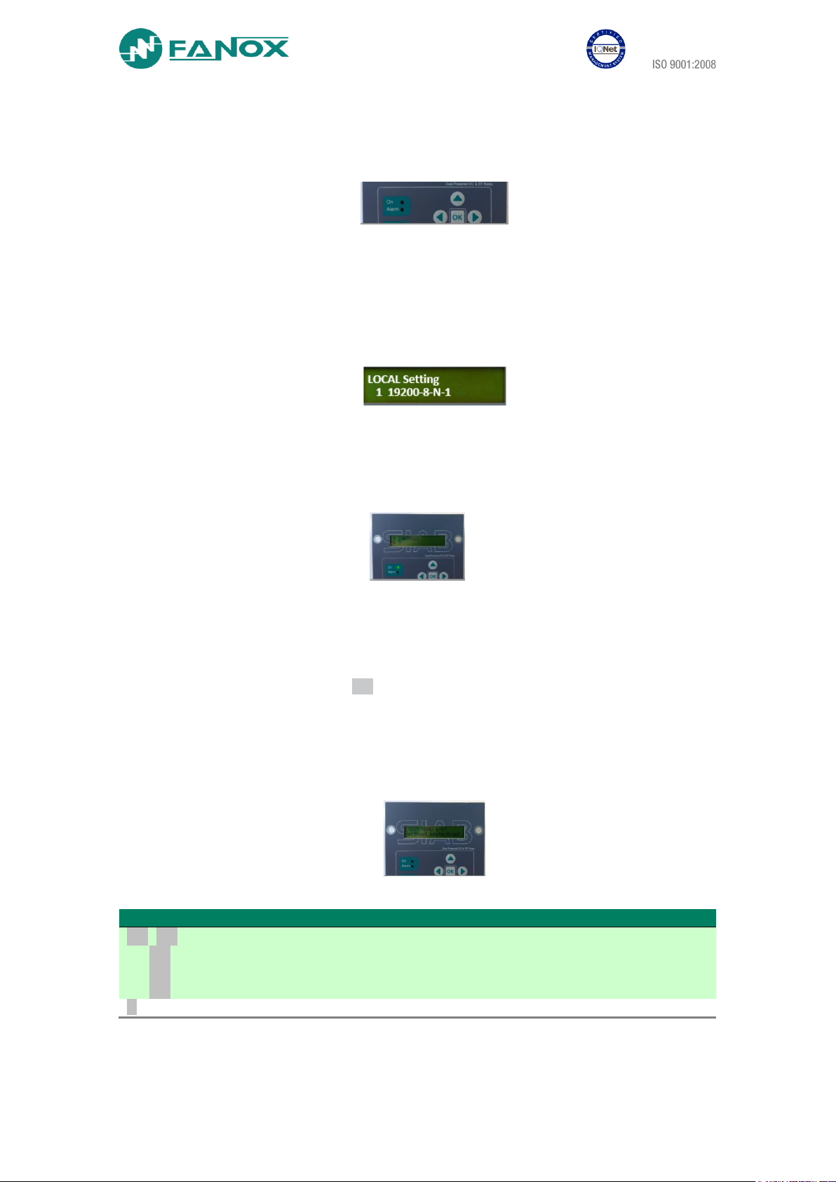
• Serial Number In “General Settings” menu serial number of 8 digits can be checked
(OK - ▼ - ▼ - ◄ - ▼ - ▼)
• Firmware Version In “Firmware Version” menu (HOLD ▲)
www.fanox.com Installation_Guide_SIAB000B0010AA_Rev. 03 5 / 32
1.3.1. Keypad & LCD
• Use KEYPAD to ensure that all the push-buttons work correctly (no difficulties while
pushing them, check out if the relay reacts by pushing each of the buttons)
• Use KEYPAD to enter in the relay´s menu and make sure that no text is lost while going
from one menu to another.
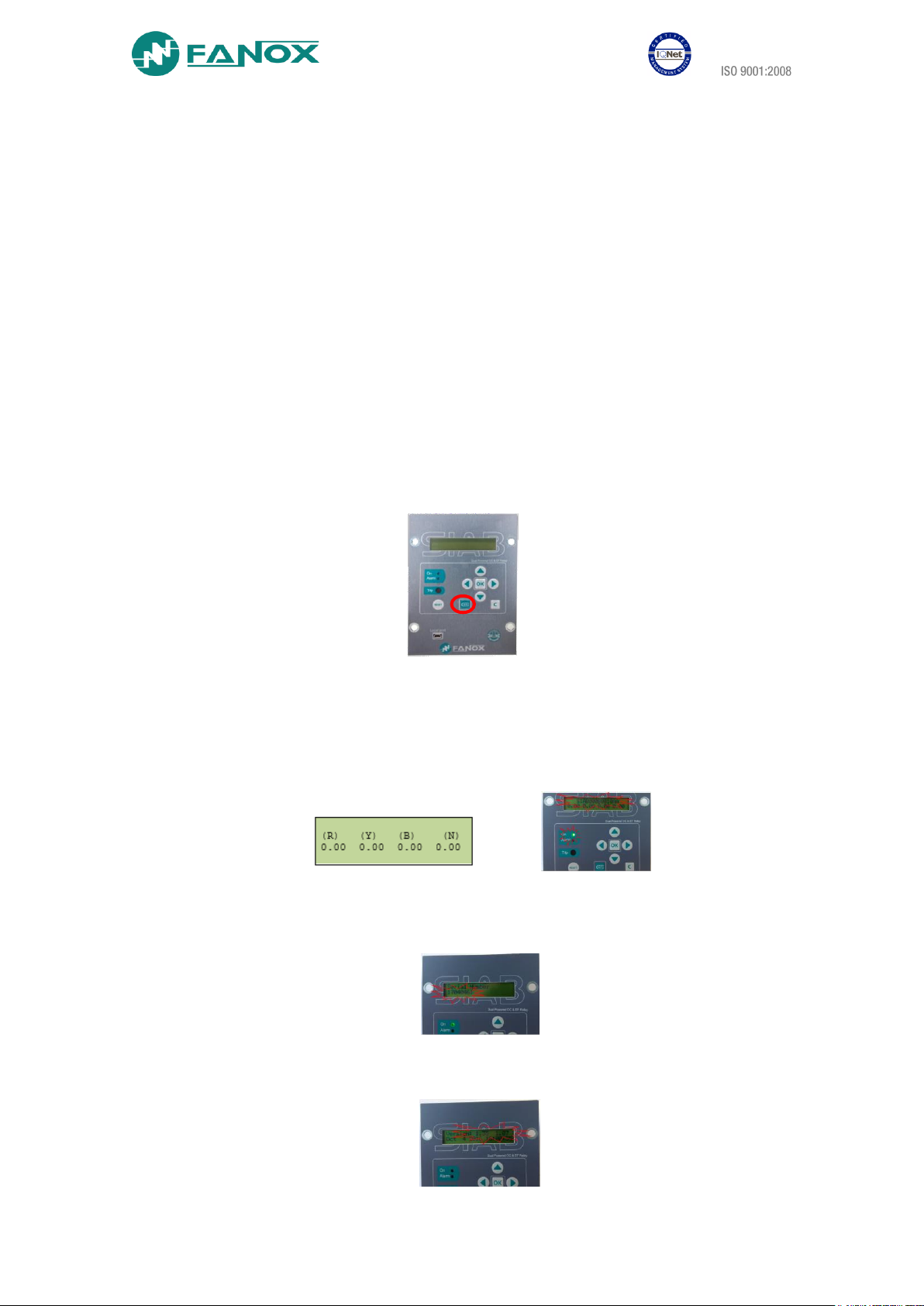
• Follow the sequence: Left ◄, Down ▼, Right ►, Up ▲, OK, C and RESET and the
following screen should be displayed:
• If the contrast of the LCD is ot the correct one, enter to “CONTRAST” menu by holding
“◄” for 3 seconds. Then, change it by using up and dwon buttons to increase or
decrease the contrast.
1.3.2. Test menu
NOTE: When performing test menu, protection won´t be available and it will be possible to open
circuit breaker. Only authorized personnel can do this job.
Press ◄,▼,► sequentially and hold OK. The relay will ask for the password “5555” to enter to
the test menu (or customer password if default “5555” has been modified).
It will be checked that the LEDs, Magnetic indicator flags and Outputs are activated if OK key is
pressed and it will be deactivated if OK key is pressed again. LEDs, Magnetic indicator and
outputs will be checked to verify the hardware is OK:
Action
Checking
OK, OK
Led ON
Led ON activated
▼, OK
Led ALARM
Led ALARM activated
▼, OK
Magnetic Indicator
Trip Magnetic indicator
▼, OK
Trip output
Trip Output activated
C
Skip from test menu
www.fanox.com Installation_Guide_SIAB000B0010AA_Rev. 03 6 / 32
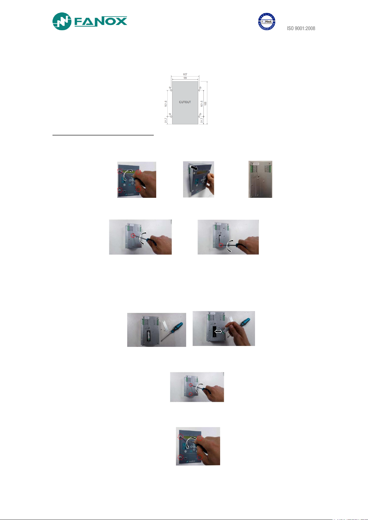
1.4. Relay intallation
To fix the relay to the switchgear, use default holes in front of relay with appropriate fixing system. Do not
manipulate relay to fix it on the switchgear.
How to change the internal battery
1. Disconnect the relay. Switch the power supply off to avoid any dangerous situation.
2. Unscrew the 4 screws on the front of the relay to extract it from the RMU and access to the
rear side of the relay.
3. Unscrew the 2 screws to remove the cover from the battery compartment.
4. Remove the battery and replace it respecting polarity (+ facing up):
Battery characteristics:
- AA 3.6V lithium battery
- Model LS14500 from SAFT
- Do not use rechargeable batteries or other types of battery
5. Put on the battery cover and tighten the 2 screws.
6. Put the relay into the RMU again and tighten the 4 screws on the front to fix the relay.

www.fanox.com Installation_Guide_SIAB000B0010AA_Rev. 03 7 / 32
Warning HAZARD OF EXPLOSION
• Do not recharge the battery.
• Do not short circuit the battery.
• Do not crush the battery.
• Do not disassemble the battery.
• Do not heat the battery above 100ºC (212ºF)
• Do not throw the battery into fire or water.
Failure to follow these instructions can result in death, severe injury, or equipment damage.
1.5. Relay rear part
Consider the wiring of the switchgear and connect relay properly:
A1
Phase A current input for measurement and self-power
C1
Trip output +
A2
Phase A current output for measurement and self-power
C2
Trip output –
A3
Phase B current input for measurement and self-power
C3-C4
External trip
A4
Phase B current output for measurement and self-power
C5
Auxiliary power supply +
A5
Phase C current input for measurement and self-power
C6
Auxiliary power supply -
A6
Phase C current output for measurement and self-power
╧ Earthing screw
1.6. Connection diagram
1.6.1. Connection diagram. Three phase diagram, neutral internally calculated
www.fanox.com Installation_Guide_SIAB000B0010AA_Rev. 03 8 / 32
2. USER INTERFACE
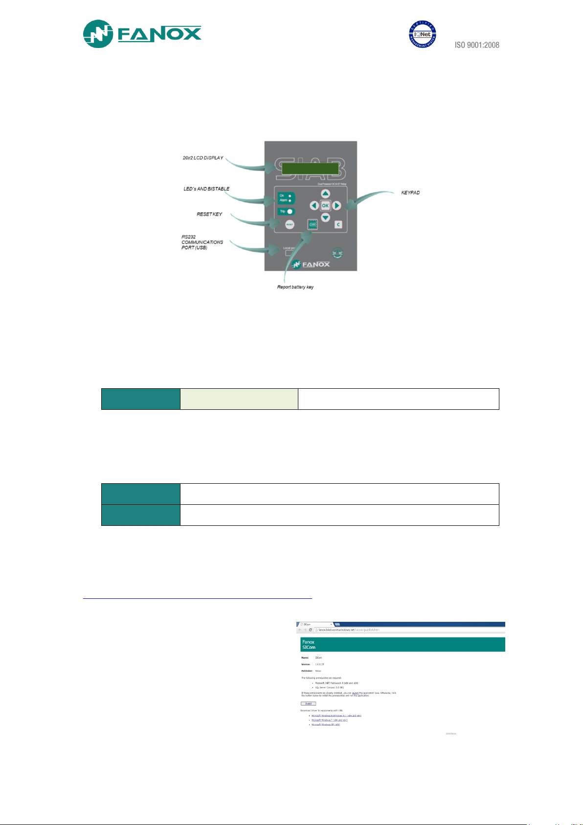
2.1. Relay front part
2.2. Bistable magnetic indicator (Flag)
The front panel is equipped with 1 bistable magnetic indicator which indicates the general trip.
The indicator remains in position even when the equipment loses power, so that the
maintenance service can see the trip even through the equipment is not powered.
Once it has been activated, it is necessary to manually reset it by pressing the “RESET” button.
The operation of the magnetic indicator can be checked from the test menu.
1 bistable
Magnetic Indicator “trip”
There is a general trip without indicating the reason.
2.3. LED indicators
The SIA-B front panel has two not configurable LEDs. By default, they show: ready (LED ON)
and alarm (LED ALARM).
LED ON
Activated (Green LED blinking) if the relay is ready
LED ALARM
Activated (Red LED blinking) if an alarm occurs.
2.4. How to install SICOMM software
To install the SICom it is necessary the following link:
http://fanox.blob.core.windows.net/sicom/publish.htm
The link will open the next screen, where key “install” must be pressed:
The necessary drivers depending on the
operative system can be downloaded from
this page. The update of the software
does not require any user´s action, this is,
if the computer is connected to Internet,
SICom updates itself when it is started.
www.fanox.com Installation_Guide_SIAB000B0010AA_Rev. 03 9 / 32
2.5. Setting-up the session: Password and access levels
Users must identify themselves with a password to start communications and to change the
equipment settings or configuration using the HMI. Depending on the access level, it may or
may not be possible to perform the operations shown on the table below.
ACCESS LEVEL
Read-only permission:
Status and
measurements
Settings
Events
Permission to:
Change settings
Download and Delete the
Events buffer
Permission to:
Execute Commands
Permission to:
Change Configuration
Permission to Change
Protected Settings
1
YES
YES
NO
NO
YES
2
YES
YES
NO
NO
NO
3
YES
NO
YES
NO
NO
4
YES
YES
YES
NO
NO
5
YES
YES
YES
YES
NO
Four passwords and their associated levels of access are set up when the equipment is
configured using the SIcom program. By default, the equipment is programmed with the
following passwords and their associated levels:
PASSWORD
ACCESS LEVEL
2222
2
3333 3 4444 4 5555
5
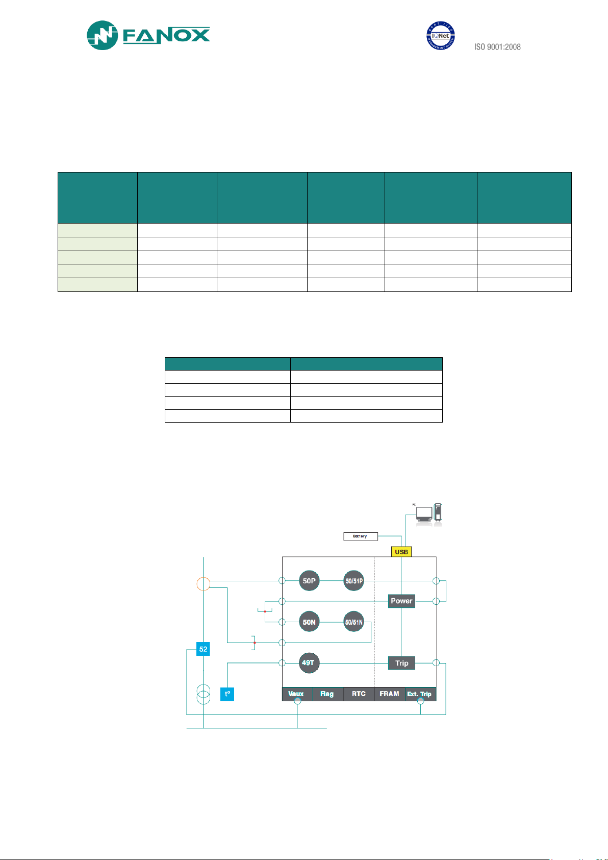
3. FUNCTIONAL DIAGRAM

www.fanox.com Installation_Guide_SIAB000B0010AA_Rev. 03 10 / 32
4. TECHNICAL SPECIFICATIONS
Complete model
SIAB000B0010AA
0: Phase measurement Defined by General Settings.
0: Neutral measurement Internal measurement.
0: Net frequency Defined by General settings.
B: Power supply Self-powered + 230 Vac (Dual) + Commissonig battery
0: Additional functions none.
0: Communications USB (modubs RTU)
1: Inputs–Outputs Trip (for Striker) + External trip input (49T) + 1 magnetic indicator
0: Mechanics Vertical. Assembly.
A: Languages English, Spanish and German
A: Adaptation -
Function 50
Permission: yes/no
Operating range: 0.20 to 20 x Is (step 0.01 x Is)
Operating time: 0.02 to 300 s (step 0.01 s)
Activation level 100%
Deactivation level 90%
Instantaneous deactivation
Timing accuracy: ± 40 ms or ± 0.5% (whichever is greater)
Function 50N
Permission: yes/no
Operating range: 0.20 to 20 x Is (step 0.01 x Is)
Operating time: 0.05 to 300 s (step 0.01 s)
Activation level 100%
Deactivation level 90%
Instantaneous deactivation
Timing accuracy: ± 40 ms or ± 0.5% (whichever is greater)
Function 50/51
Permission: yes/no
Operating range: 0.20 to 7 x Is (step 0.01 x Is)
Curves: IEC 60255-151 and IEEE
Operating time: IEC Inverse curve, IEC very inverse curve, IEC extremely inverse curve
IEC long time inverse, IEEE Inverse curve, IEEE very inverse curve, IEEE extremely
inverse curve.
Defined time: 0.02 to 300 s (step 0.01 s)
Dial: 0.05 to 1.25 (step 0.01)
Curve, activation level 110%
Curve, deactivation level 100%
Defined time, activation level 100%
Defined time, deactivation level 90%
Instantaneous deactivation
 Loading...