

FANOX SIA-B User Manual

USER´S MANUAL
L
SIA B
Self and Dual powered
Overcurrent & Earth Fault Protection Relay

www.fanox.com SIAB_ENG_V1 2/81
1. RECEPTION, HANDLING & INSTALLATION .................................................................................. 5
1.1. Unpacking ........................................................................................................................................ 5
1.2. Reception of relays.......................................................................................................................... 5
1.3. Handling electronic equipment ...................................................................................................... 5
1.4. Installation, commissioning and service ...................................................................................... 5
1.5. Storage ............................................................................................................................................. 6
1.6. Recycling .......................................................................................................................................... 6
2. DIMENSIONS AND CONNECTION DIAGRAMS ............................................................................. 7
2.1. Frontal view ...................................................................................................................................... 7
2.2. Case dimensions ............................................................................................................................. 8
2.3. Connection diagram ........................................................................................................................ 9
2.4. Terminals .......................................................................................................................................... 10
3. DESCRIPTION .................................................................................................................................. 11
3.1. Introduction ...................................................................................................................................... 11
3.2. Equipment description .................................................................................................................... 11
3.3. Functional Diagram ......................................................................................................................... 13
3.4. Model List ......................................................................................................................................... 14
3.5. Specific CTs ..................................................................................................................................... 15
4. PROTECTION FUNCTIONS ............................................................................................................. 17
4.1. 50P Function. Phase instantaneous phase overcurrent ............................................................. 17
4.2. 51P Function. Phase inverse time overcurrent ............................................................................ 17
4.3. 50N Function. Neutral instantaneous overcurrent ....................................................................... 18
4.4. 51N Function. Neutral inverse time overcurrent .......................................................................... 19
4.5. Trip blocking protection for the switchgear ................................................................................. 19
4.6. 49 Function. Thermal Image Protection ........................................................................................ 20
4.7. External trip ...................................................................................................................................... 23
4.8. General Settings .............................................................................................................................. 23
4.9. Setting Group ................................................................................................................................... 23
4.10. IEC 60255-151 Curves ..................................................................................................................... 24
5. MONITORING AND CONTROL ........................................................................................................ 28
5.1. Measurements .................................................................................................................................. 28
5.2. States and Events ............................................................................................................................ 28
5.3. Fault Reports .................................................................................................................................... 32
5.4. Date and Time by Real Time Clock (RTC) ..................................................................................... 32
5.5. Self-diagnosis .................................................................................................................................. 32
5.6. Commands ....................................................................................................................................... 33
5.7. Test Menu ......................................................................................................................................... 33
5.8. Power supply ................................................................................................................................... 34

www.fanox.com SIAB_ENG_V1 3/81
5.8.1. Self-Powered relay with specific current transformers ...................................................... 34
5.8.2. 230 Vac or 110 Vac, 50/60 Hz auxiliary power ...................................................................... 34
5.8.3. 24 Vdc auxiliary power supply .............................................................................................. 34
5.8.4. Battery power: 5 V, with a KITCOM adaptor......................................................................... 34
5.9. Opening mechanism: STRIKER ..................................................................................................... 35
6. TECHNICAL SPECIFICATIONS AND STANDARDS ...................................................................... 36
6.1. Technical Specifications ................................................................................................................. 36
6.2. Standards ......................................................................................................................................... 39
7. COMMUNICATION AND HMI ........................................................................................................... 41
7.1. Front Communication: USB ........................................................................................................... 41
7.2. Indicators .......................................................................................................................................... 41
7.3. LCD and keypad ............................................................................................................................... 42
7.4. SICom Communications program ................................................................................................. 42
7.5. MENUS .............................................................................................................................................. 43
7.5.1. Standby mode screen ............................................................................................................. 43
7.5.2. Accessing the menus ............................................................................................................. 43
7.5.3. Date-time menu ....................................................................................................................... 44
7.5.4. Versions ................................................................................................................................... 44
7.5.5. Communication parameters .................................................................................................. 44
7.5.6. Fault report .............................................................................................................................. 44
7.5.7. Test Menu ................................................................................................................................ 45
7.5.8. Functions Menu ...................................................................................................................... 47
7.5.9. Measurements Menu .............................................................................................................. 48
7.5.10. States Menu ............................................................................................................................. 49
7.5.11. Settings Menu ......................................................................................................................... 57
7.5.12. Events Menu ............................................................................................................................ 64
7.5.13. Commands Menu .................................................................................................................... 66
8. MODBUS RTU PROTOCOL ............................................................................................................. 67
8.1. ModBus packaged format ............................................................................................................... 68
8.2. Function codes ................................................................................................................................ 68
8.3. Exemptions and error answers ...................................................................................................... 69
8.4. Data type ........................................................................................................................................... 69
8.5. Memory map of SIA-B ..................................................................................................................... 70
8.6. Commands Map ............................................................................................................................... 74
8.7. Examples of ModBus frames ......................................................................................................... 74
8.7.1. Writing the access password “5555” to equipment nº 1 .................................................... 74
9. COMMISSIONING ............................................................................................................................. 75
9.1. Checklist for Commissioning ......................................................................................................... 75
9.2. Electrostatic discharge ................................................................................................................... 75

www.fanox.com SIAB_ENG_V1 4/81
9.3. Visual Inspection ............................................................................................................................. 75
9.4. Earthing ............................................................................................................................................ 75
9.5. Current transformers....................................................................................................................... 75
9.6. Auxiliary power ................................................................................................................................ 75
9.7. Front communications port ............................................................................................................ 75
9.8. Commissioning ................................................................................................................................ 76
10. APPENDIX ........................................................................................................................................ 77
10.1. Identification .................................................................................................................................... 77
10.2. Checks .............................................................................................................................................. 77
10.3. Test menu ......................................................................................................................................... 77
10.4. Register of commissioning settings.............................................................................................. 77
10.5. Comments ........................................................................................................................................ 79

www.fanox.com SIAB_ENG_V1 5/81
1. RECEPTION, HANDLING & INSTALLATION
1.1. Unpacking
Relays must only be handled by qualified personnel and special care must be taken to protect all
of their parts from any damage while they are being unpacked and installed. The use of good
illumination is recommended to facilitate the equipment visual inspection.
The facility must be clean and dry and relays should not be stored in places that are exposed to
dust or humidity. Special care must be taken if construction work is taking place.
1.2. Reception of relays
It is necessary to inspect the equipment at the time it is delivered to ensure that the relays have
not been damaged during transport.
If any defect is found, the transport company and FANOX should be informed immediately.
If the relays are not for immediate use, they should be returned to their original packaging.
1.3. Handling electronic equipment
Relays contain an electronic component that is sensitive to electrostatic discharges.
Just by moving, a person can build up an electrostatic potential of several thousand volts.
Discharging this energy into electronic components can cause serious damage to electronic
circuits. It is possible that this damage may not be detected straight away, but the electronic circuit
reliability and life will be reduced. This electronic component in the equipment is well protected by
the metal housing, which should not be removed as the equipment cannot be adjusted internally.
If it is necessary to disassemble the electronic component, this must be carried out with care and
contact with electronic components, printed circuits and connections must be avoided to prevent
an electrostatic discharge that could damage one of the components. If the electronic components
are stored outside the metal housing, they must be placed in an antistatic conductive bag.
If it is necessary to open a module, care must be taken to preserve the equipment reliability and
the duration of the life cycle as designed by the manufacturer by taking the following actions:
Touch the housing to ensure that you have the same potential
Avoid touching the electronic components and handle the module by its edges.
Remember that everyone who handles the module must have the same potential.
Use a conductive bag to transport the module.
For more information about how to handle electronic circuits, consult official documents such as
the IEC 147-OF.
1.4. Installation, commissioning and service
The personnel in charge of installing, commissioning and maintaining this equipment must be
qualified and must be aware of the procedures for handling it. The product documentation should
be read before installing, commissioning or carrying out maintenance work on the equipment.

www.fanox.com SIAB_ENG_V1 6/81
Personnel should take specific protection measures to avoid the risk of electronic discharge when
access is unlocked on the rear part of the equipment.
In order to guarantee safety, the crimp terminal and a suitable tool must be used to meet isolation
requirements on the terminal strip. Crimped terminations must be used for the voltage and current
connections.
It is necessary to connect the equipment to earth through the corresponding terminal, using the
shortest possible cable. As well as guaranteeing safety for the personnel, this connection allows
high frequency noise to be evacuated directly to earth.
The following checks must be performed before the equipment is supplied:
The rated voltage and polarity.
The power rating of the CT circuit and the integrity of the connections.
The integrity of the earth connection.
The equipment must be used within the stipulated electrical and environmental limits.
Note: Regarding the current transformer circuits: Do not open a live CT secondary circuit. The high
voltage produced as a result could damage the isolation and threaten lives.
1.5. Storage
If the relays are not going to be installed immediately, they must be stored in a dust- and humidity
free environment after the visual inspection has been performed.
1.6. Recycling
Before recycling the equipment, the capacitors should be discharged through the external
terminals. All electrical power sources should be removed before performing this operation to
avoid the risk of electrical discharge.
This product must be disposed of in a safe way. It should not be incinerated or brought into contact
with water sources like rivers, lakes, etc…
www.fanox.com SIAB_ENG_V1 7/81
2. DIMENSIONS AND CONNECTION DIAGRAMS
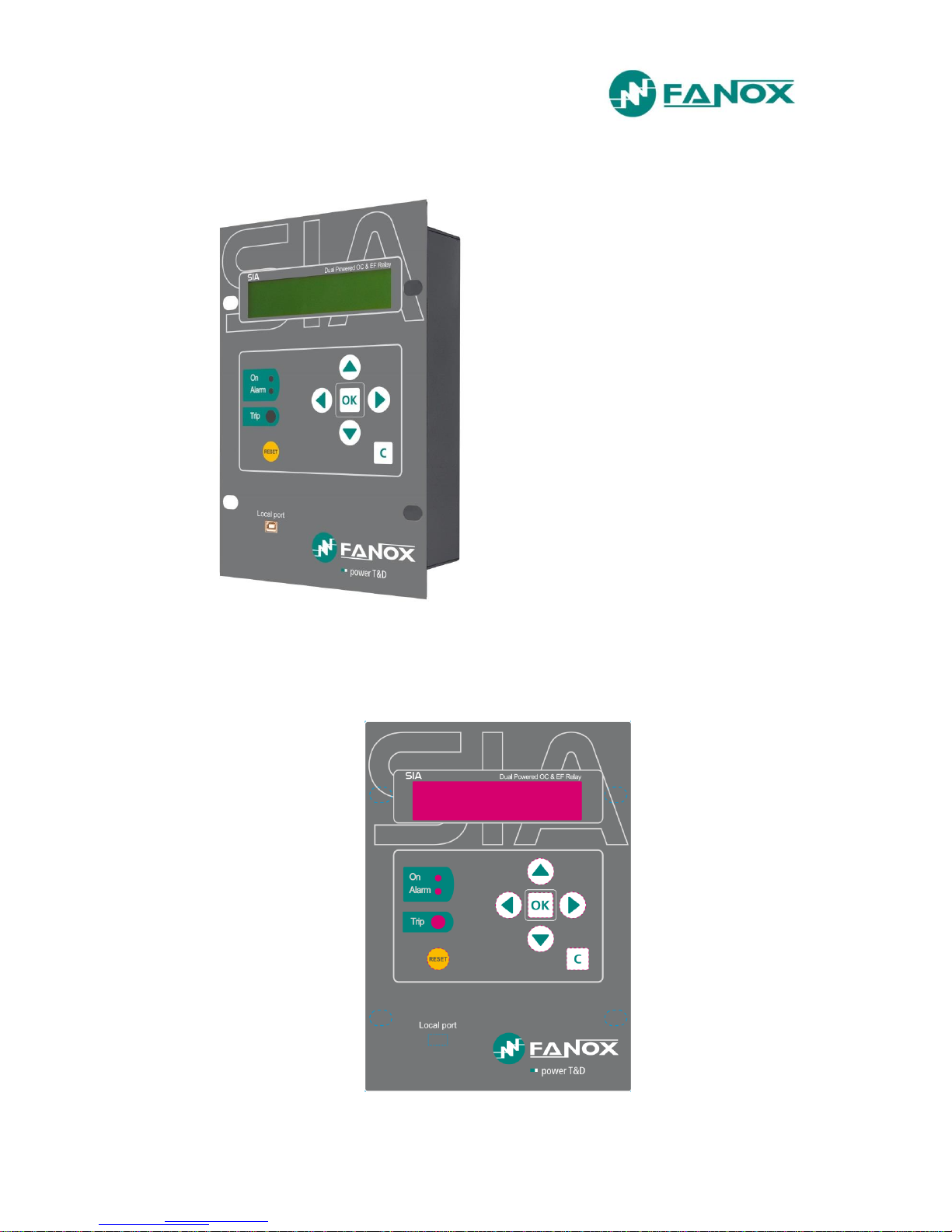
2.1. Frontal view
www.fanox.com SIAB_ENG_V1 8/81
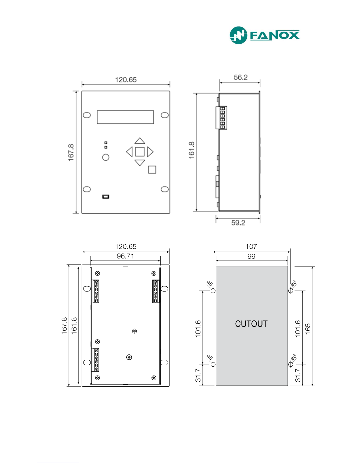
2.2. Case dimensions
The dimensions are in mm.
www.fanox.com SIAB_ENG_V1 9/81
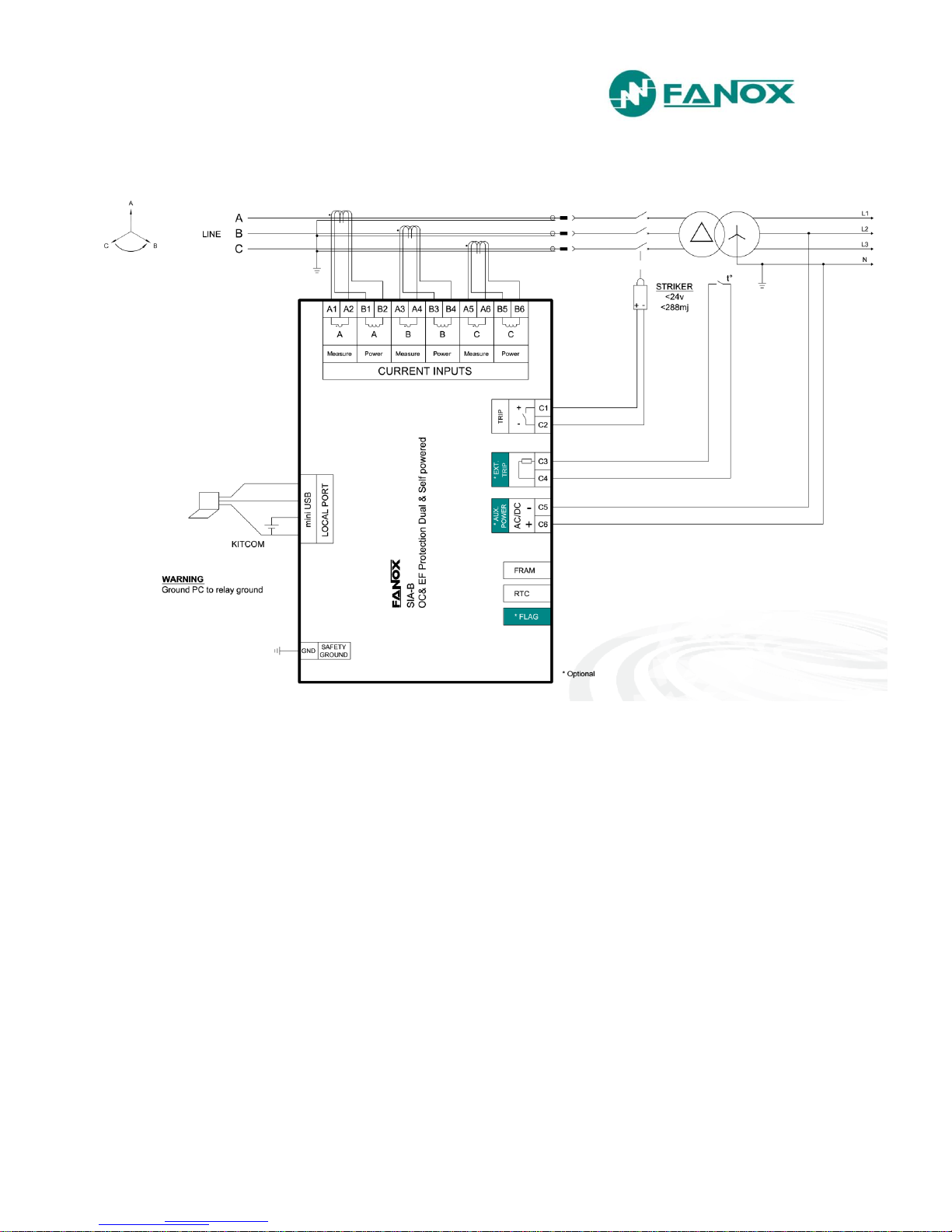
2.3. Connection diagram
NOTE! STRIKER: 6 – 24 Vdc & < 0,1 Ws
www.fanox.com SIAB_ENG_V1 10/81
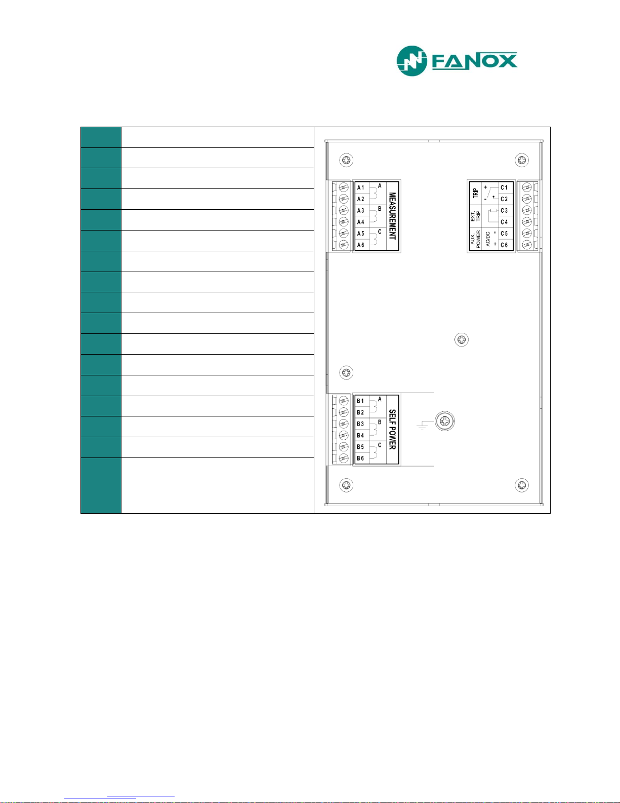
2.4. Terminals
A1
Phase A current input for measurement
A2
Phase A current output for measurement
A3
Phase B current input for measurement
A4
Phase B current output for measurement
A5
Phase C current input for measurement
A6
Phase C current output for measurement
B1
Phase A current input for power supply
B2
Phase A current output for power supply
B3
Phase B current input for power supply
B4
Phase B current output for power supply
B5
Phase C current input for power supply
B6
Phase C current output for power supply
C1
Trip output +-
C2
Trip output -
C3-C4
External trip
C5
Auxiliary power supply -
C6
Auxiliary power supply +

www.fanox.com SIAB_ENG_V1 11/81
3. DESCRIPTION
3.1. Introduction
Worldwide, the energy sector is currently undergoing a profound change as a result of high levels
of energy demand; more distribution lines and advanced supervision systems are required. Given
the need for creating intelligent infrastructure, FANOX has developed the SIA family of products to
carry out this function.
The family of SIA relays is designed to protect the secondary transformation and distribution
centres of electricity grids. Protection features include protection against instantaneous and
inverse time overcurrent (for the phases and the neutral), and it also has external trip support
(temperature, pressure, etc.) depending on the characteristics of each model.
The protection functions can be enabled selectively by using both the front panel and the
communications links to the SICom program, allowing for precise coordination with other
equipment.
Additional benefits include that all of the models have been designed to be supplied from an
external battery. This is aimed at facilitating event management and the commissioning of centres,
as well as allowing it to operate properly under adverse conditions.
3.2. Equipment description
The SIA-B equipment is a protection relay designed for secondary distribution. One of its main
characteristics is the necessity of using specific current transformers for measurement and power
supply.
The equipment starts-up from 0.4xIsmin three phase
current using specific CTs.
The SIA-B equipment is housed in a metal box with
galvanic isolation on all of its measurement inputs and
outputs (with the exception of ports for communications
and battery power supply, as these are sporadic
connections). This allows the equipment to have the
best possible level of electromagnetic compatibility,
both in terms of emission of, and immunity from,
radiated and conducted interferences. These levels are
the same as those established for primary substations.
The equipment has a LCD with two lines and twenty
columns and a membrane keyboard with six buttons.
These allow the display of the equipment state, the
current measurements in the primary and the events or
incidents associated with the equipment, and
adjustments to be made to the protection criteria.
There are two LED indicators on the front of the SIA-B
equipment. These indicate if the equipment is On (LED ON) and if an alarm has happened (LED
ALARM). Depending on model, there is a possibility of having, apart from the LEDS, one bistable
indicator to signaling the trip of any of the protection functions.
In order to facilitate the analysis of events, it is fitted with four fault reports. Each register includes
the events that have occurred during the incident.
The equipment has storage for up to 100 events, allowing any recorded incidents to be analyzed.
All SIA-B models are equipped with a real-time clock (RTC).

www.fanox.com SIAB_ENG_V1 12/81
Current measurements are performed using RMS values. Specific current transformers (CTs) are
used.
The equipment has a frontal communication port (miniUSB). This port allows a PC to be
connected, which can be used to monitor the equipment using the SICom communications
program (supplied by FANOX). Besides, the frontal port can be used to power the equipment by
using an USB cable which can be directly connected with PC.
The protective functions provided, easy-to-use interface, low amount of maintenance and simple
integration make the SIA-B a precise and practical solution for protecting both industrial and public
electrical grids and transformation and distribution centers. The main features of the equipment are
listed below, and these features will be explained in the rest of the manual:
Function
Description
SIA-B
Protection
50P
Phase instantaneous overcurrent protection function
1
50N
Neutral instantaneous overcurrent protection function
1
51P
Phase inverse time overcurrent protection function
1
51N
Neutral inverse time overcurrent protection function
1
Fuse +
Switchgear
Trip blocking to protect the switchgear
1 (optional)
49
Thermal image
1 (optional)
Measurements
Phase and neutral RMS measurement with 2% accuracy on a
band of ±20% over the nominal current and 4% over the rest
of the range.
IA, IB, IC, IN, Imax and TI
Inputs and Outputs
External trip input (without power supply)
Optional
Trip output for STRIKER
1
Communication and HMI
Front port: USB (ModBus, RTU 19200)
SICom Program
HMI: LCD, 20x2 and 6 keys + 1 reset button
LED Indicators
2
Bistable indicator
1 (optional)
www.fanox.com SIAB_ENG_V1 13/81
Power supply
Self-powered with specific CTs (0.4xIs three phase)
Auxiliary power: 230 Vac, 50/60 Hz
Optional
Auxiliary power: 110 Vac, 50/60 Hz
Optional
Auxiliary power: 24 Vdc
Optional
Battery power accessory: 5 V with Kitcom adaptor
Monitoring and recording
Events saved in the non-volatile FRAM* memory
100
Commands
Optional
Real-Time Clock (RTC)
Fault reports
4
Test menu
Self-diagnosis
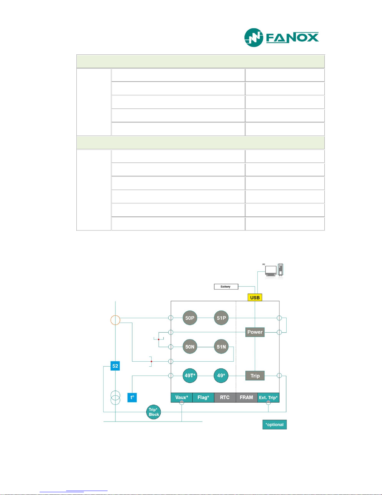
3.3. Functional Diagram

www.fanox.com SIAB_ENG_V1 14/81
3.4. Model List
TYPE
CT TYPE
NEUTRAL MEASUREMENT
NET FREQUENCY
POWER SUPPLY
ADDITIONAL FUNCTIONS
COMMUNICATIONS
INPUTS - OUTPUTS
MECHANICS
LANGUAGE
ADAPTATION
Dual Powered OC &
EF Relay
SIAB
50P+51P+50N+51N
0
Defined by General Setting
0
Internal measurement
0
Defined by General Setting
0
1
2
3
Self-powered
Dual-powered at 230 Vac
Dual-powered at 110 Vac
Dual-powered at 24 Vdc
0
1
B
+ 49
+ Trip Block for switch disconnector
0
USB frontal
0 1
2 led’s + trip output (striker)
+ External trip input (49T) + 1 FLAG
0
A
B
C
D
English, Spanish and German
English, Spanish and Turkish
English , Spanish and French
English , Spanish and Russian
A
-
www.fanox.com SIAB_ENG_V1 15/81
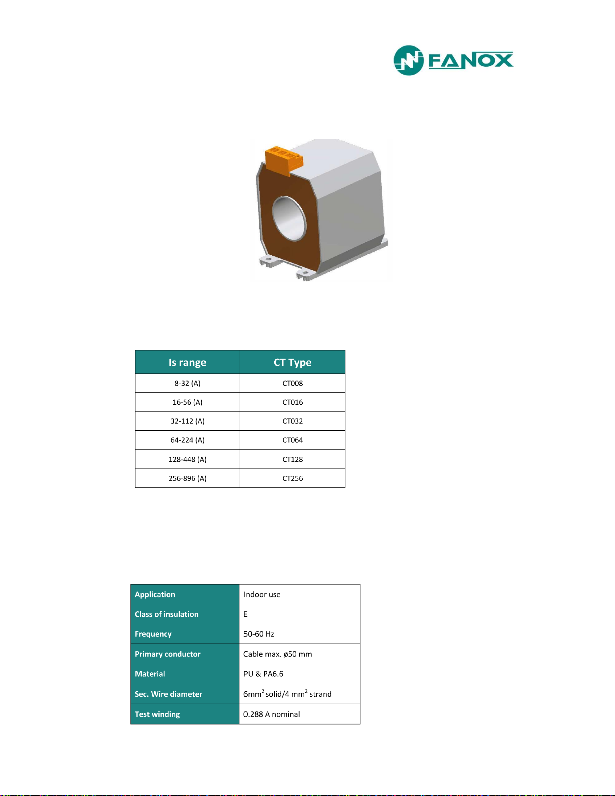
3.5. Specific CTs
SIAB relay requires specific CTs to achieve the measurement and the power supply:
Depending on the model we select, we have the following primary currents:
The main characteristics of the transformers are:
Technical specifications:
www.fanox.com SIAB_ENG_V1 16/81
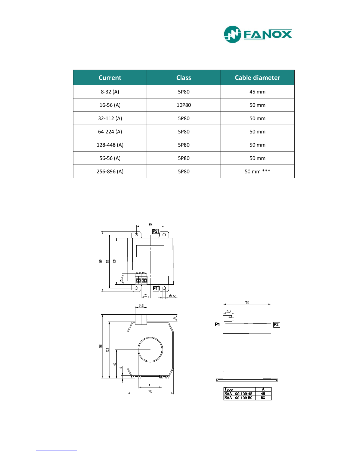
Ordering specifications:
*** Different shape drawing on request
Dimensions:

www.fanox.com SIAB_ENG_V1 17/81
4. PROTECTION FUNCTIONS
4.1. 50P Function. Phase instantaneous phase overcurrent
This protection function can be set by using three parameters:
Function
Description
Minimum
Maximum
Step
Unit
Default
50P
Phase instantaneous overcurrent
Permission
- - Yes/No - No
Tap
0,10
20,00
0,01
Is
5,00
Operating time
0,02
300,0
0,01 s 0,02
The operating time is independent from the operating current flowing through the equipment, so if
the phase current exceeds its predetermined value for an equal or greater amount of time than this
pre-set value, the protection function activates (trips) and does not reset itself until the value of the
phase drops below the point of current tap.
The function activates at 100% of the pre-set input, and deactivates at 95%. The reset is
instantaneous.
The accuracy of the operating time is equal to the pre-set time plus a maximum of 30 ms.
4.2. 51P Function. Phase inverse time overcurrent
This protection function can be set by using five parameters:
Function
Description
Minimum
Maximum
Step
Unit
Default
51P
Phase inverse time overcurrent
Permission
- - Yes/No
-
No
Curve - -
(1*)
-
Extremely Inverse
Dial
0,05
1,25
0,01
-
1,25
Tap
0,10
7,00
0,01
Is
1,00
Operating time
0,02
300,0
0,01
s
0,02
(1*) Inverse, Very inverse, Extremely inverse, Defined time

www.fanox.com SIAB_ENG_V1 18/81
If the option "Defined time" is selected for the curve setting, the unit behaves like an instantaneous
overcurrent unit. In this case, the unit operating time is set by the parameter "Operating time".
If a curve (inverse, very inverse or extremely inverse) is selected for the curve setting, the
operating time depends on the curve, dial and tap settings.
If the unit operates with defined time, the function is activated at 100% of the set tap value, and it
deactivates at 95%.
If the unit operates with a curve, the function is activated at 110% of the set tap value, and it
deactivates at 100%.
The reset is instantaneous in both cases.
The activation time is accurate to ±5% or ±30ms, whichever is greater, of the theoretical activation
time.
The curves used are IEC 60255-151, which are described in the "Curves" section.
4.3. 50N Function. Neutral instantaneous overcurrent
This protection function can be set by using three parameters:
Function
Description
Minimum
Maximum
Step
Unit
Default
50N
Neutral instantaneous overcurrent
Permission
-
-
Yes/No - No
Tap
0,10
20,00
0,01
I s
1,00
Operating time
0,02
300,00
0,01 s 0,02
The operating time is completely independent from the operating current that flows through the
equipment, so if the neutral current exceeds its predetermined value for an equal or greater
amount of time than this pre-set value, the protection function activates (trips) and does not reset
itself until the value of the phase drops below the point of current pick-up.
The function activates at 100% of the pre-set input, and deactivates at 95%. The reset is
instantaneous.
The accuracy of the operation time is equal to the pre-set time plus a maximum of 30 ms.

www.fanox.com SIAB_ENG_V1 19/81
4.4. 51N Function. Neutral inverse time overcurrent
This protection function can be set by using the following parameters:
Function
Description
Minimum
Maximum
Step
Unit
Default
51N
Neutral inverse time overcurrent
Permission
- - Yes/No - No
Curve - -
(1*)
-
Extremely Inverse
Dial
0,05
1,25
0,01 - 1,25
Tap
0,10
7,00
0,01
Is
0,50
Operating time
0,02
300,0
0,01 s 0,02
(1*) Inverse, Very inverse, Extremely inverse, Defined time
If the option "Defined time" is selected for the curve setting, the unit behaves like an instantaneous
overcurrent unit. In this case, the unit operating time is adjusted by using the parameter "Operating
time".
If a curve (inverse, very inverse or extremely inverse) is selected for the curve setting, the
operating time depends on the curve, dial and tap settings.
If the unit operates as defined time, the function is activated at 100% of the set tap value, and it
deactivates at 95%.
If the unit operates with a curve, the function is activated at 110% of the set tap value, and it
deactivates at 100%. The reset is instantaneous in both cases.
The activation time is accurate to ±5% or ±30ms, whichever is higher, of the theoretical activation
time.
The curves used are IEC 60255-151, which are described in the "Curves" section.
4.5. Trip blocking protection for the switchgear
Some transformation centers use a combination of switchgear and fuses for cutting out.
Switchgears have a limited opening current. As a result, the fuses are responsible for cutting out
the circuit for high current short circuits, as the switchgear would be destroyed if opened in this
situation. In order to deal with these situations, tripping is blocked when the phase current exceeds
a pre-set value.
Group
Description
Minimum
Maximum
Step
Unit
Default
Trip blocking
Blocking - -
Yes/No
-
Yes
Blocking limit
1,50
20,00
0,01
I nominal
7,00

www.fanox.com SIAB_ENG_V1 20/81
4.6. 49 Function. Thermal Image Protection
Thermal image is a measure of heating and cooling of an electric machine. Unlike overcurrent
protection, do not start counting the time when it detects a fault, but is continuously determining
the thermal state of the machine that monitors. The trip time depends on the thermal constants
adjusted, the current flowing and the prior thermal state of the machine.
The thermal image is calculated based on the following equation:
θ = 100 x (I/It)2 x (1 – e
-t/ζ
) + θ’0 x e
-t/ζ
Where:
I, maximum R.M.S. current of three phases
I
t,
adjusted tap current
ζ, thermal constant
θ’
0
, initial thermal state
The trip time is given by the equation:
t = ζ x ln x {[(I/It) 2 –
(θ’
0
/ 100)] / [(I/It) 2 - 1]}
The accuracy of the tripping time is 5% of the theoretical time.
The algorithm uses the maximum of the three phase currents. If the maximum is greater than 15%
of the adjusted tap, heating thermal constant is applied. If the maximum is less than 15% of the
adjusted tap cooling thermal constant is taken into account.
The overload function trips when the thermal image reaches the value of 100%. This value is
reached in time when the current flowing is equal to the function adjusted in thermal function.
It provides an adjustable level of thermal imaging to generate an alarm. If the trip occurs, the
function of overload is reset when the thermal image falls below the set alarm level.
As the current measurement algorithm used is R.M.S., in the thermal model is taken into account
the heat produced by the harmonics.
This protection function is adjusted by setting five different parameters:
Function
Description
Minimum
Maximum
Pitch
Unit
Default
49
Thermal image protection function
Permission
- - Yes/No - No
Tap
0,10
2,40
0,01
Is
1,2
ζ heating
3
600 1 min
3
ζ cooling 1 6
1
ζ heating
1
Alarm
20
99 1 %
80
www.fanox.com SIAB_ENG_V1 21/81
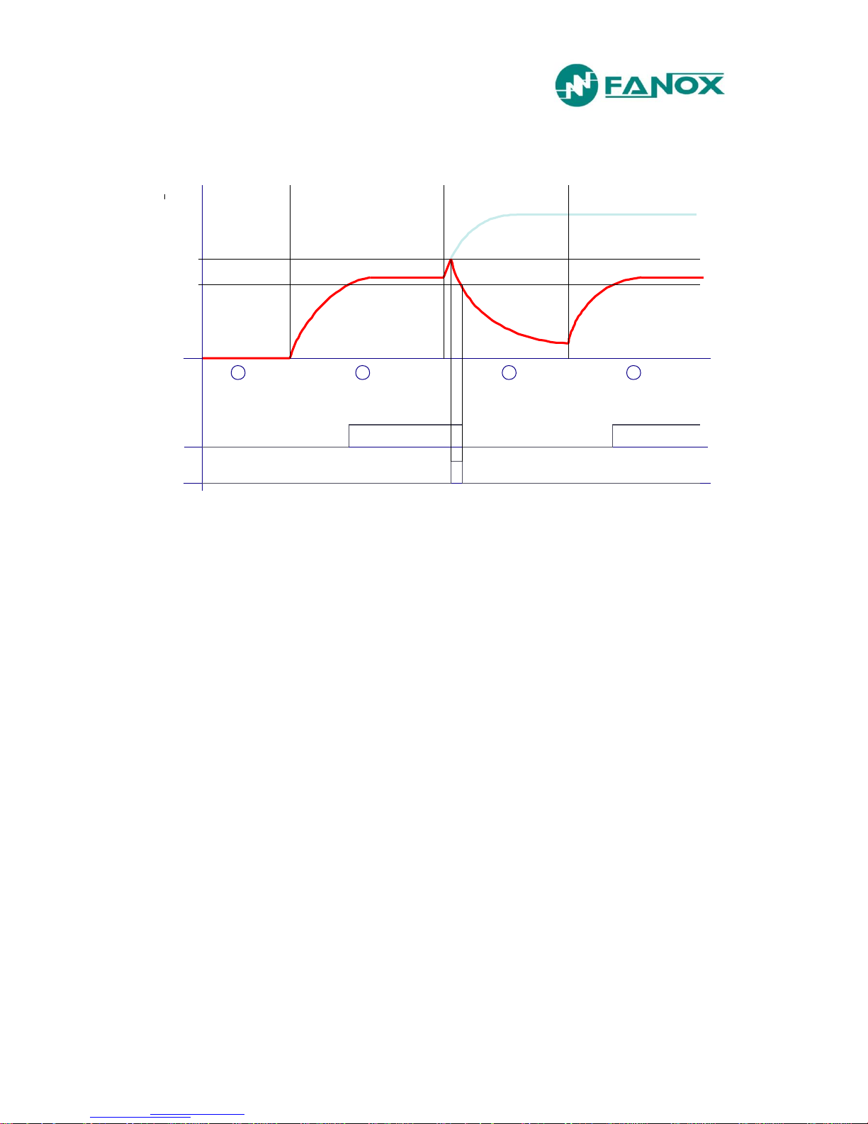
4.6.1. Thermal image measurement evolution graphic
On next graphic, thermal image measurement evolution can be observed depending on applied
current:
We suppose that thermal image protection has and adjusted tap of 1,1 times the nominal current
and an alarm level of 75%.
Zone 1: The machine is de-energized for a long time. Thermal image is 0%.
Zone 2: We supply the machine with the nominal current. Thermal image evolutions so as
to get the value of the thermal balance corresponding to one time the nominal current Th =
(I/It) 2 = 82%. The time that it takes in getting the thermal balance depends on the adjusted
heating constant.
Zone 3: Once reached the thermal image corresponding to the application of one time the
nominal current, we apply 1,2 times the nominal current. Thermal image would evolve so
as to get the thermal balance corresponding to 1,2 times the nominal current Th = (I/It)2 =
119%. This would occur if we had the permission of the thermal function disabled. If the
permission is disabled, 49 protection function performs when the thermal image reaches
the value of 100%. Once tripped, current is cut and thermal image is getting cool based on
the cooling constant.
Zone 4: Before getting totally cool, nominal current is applied again and thermal balance is
reached once passed the time determined by the heating thermal constant.
Thermal image protection alarm bit is active if the thermal image measurement is over the
adjusted alarm level.
Thermal image protection trip bit is active when the measurement of the thermal image is over
100% and it is reset when the measurement of the thermal image is under the adjusted alarm
level.
Th %
t
100%
1 2 3 4
75%
alarm
trip

www.fanox.com SIAB_ENG_V1 22/81
4.6.2. Thermal image with memory
Thermal image is stored in non-volatile RAM memory periodically every second. By this way,
though the relay loses the power supply, it will keep the thermal state of the machine.
4.6.3. Thermal image measurement display. Reset.
Thermal image measurement can be displayed on Measurement menu and Counters menu.
Display is possible in Measurement menu. Display and thermal image value reset is possible in
Counters menu.
4.6.4. Thermal protection curves
This is the thermal curve for ζ = 3 minutes.

www.fanox.com SIAB_ENG_V1 23/81
4.7. External trip
The equipment has a direct trip input, normally connected to a bimetallic contact fitted to the
power transformer. This serves as a backup to the overcurrent functions.
It allows the connection of a bimetallic free potential contact. When this contact closes, it
activates the input.
This input is especially protected against magnetic noise.
4.8. General Settings
General settings establish some parameters that are necessary for the relay to operate. These
settings are defined as general because they affect the entire relay, and as a result they are not
subject to a change of table.
Function
Description
Minimum
Maximum
Step
Unit
Default
General settings
Equipment identifier
-
- - -
“free text”(1*)
Frequency - -
60/50
Hz
50
Serial Number
-
- - - 0 Language - - - -
English
Settings active group
1
2 1 -
1
Nominal current
8
896 1 A
16
CT type
CT008
CT256
CT008, CT016, CT032,
CT064, CT128, CT256
-
CT018
Local communication
address
1
247 1 -
1
Password
****
**** - -
5555
(1*) “EQUIPMENT IDENTIFIER” setting it is only adjustable by communications.
The serial number is only a reading setting
The rest of the settings can be changed either from the HMI or through communications.
Any change of set values will restart all functions, irrespective they are activated or not.
4.9. Setting Group
There are available two protection setting groups. The setting group, which is activated in a
particular moment, can be modified in the following way:
Changing active group. In general settings menu there is an option to establish which
group is active.

www.fanox.com SIAB_ENG_V1 24/81
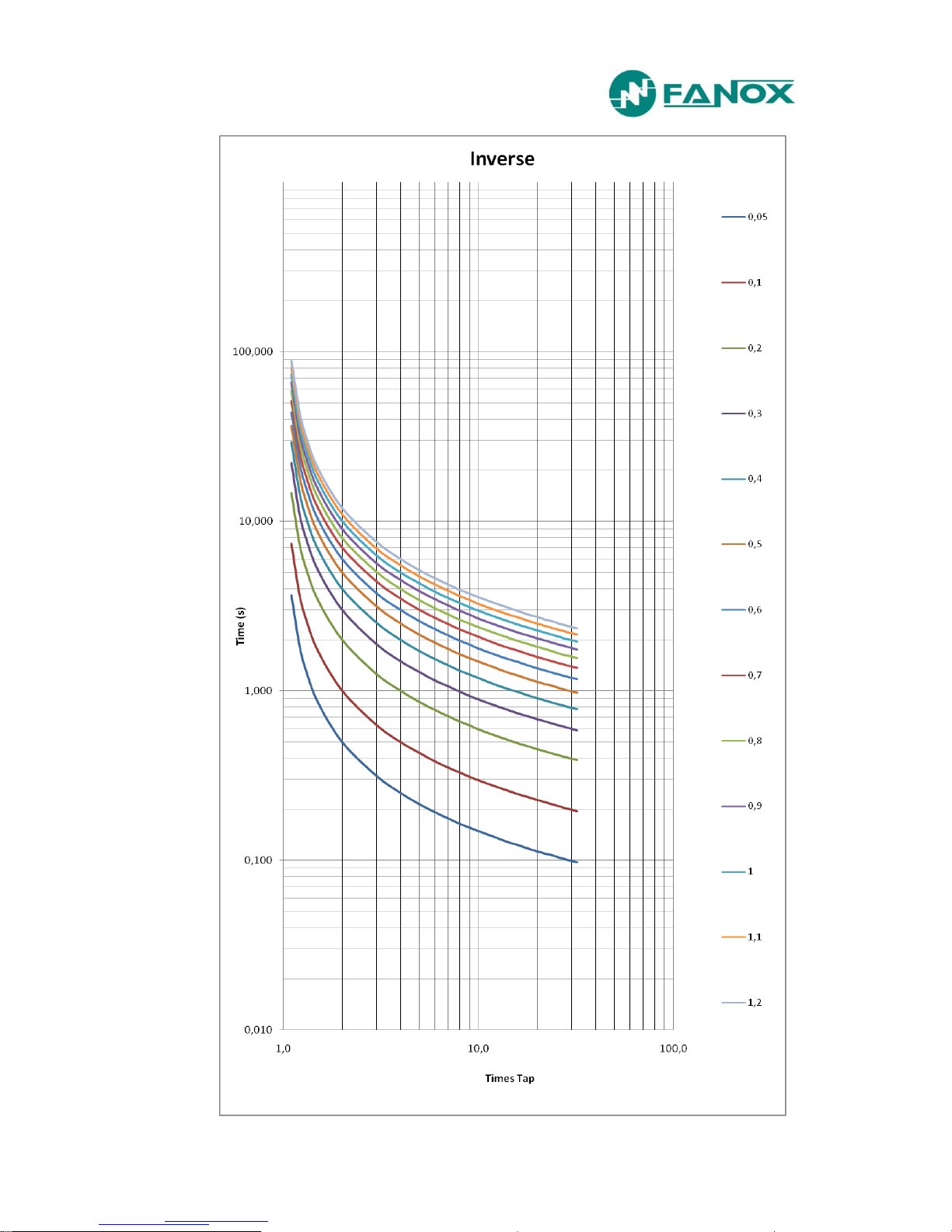
4.10. IEC 60255-151 Curves
The SIA-B relay complies with the curves shown in standard IEC 60255-151 Curves:
Inverse Curve
Very Inverse Curve
Extremely Inverse Curve
There is a general mathematical equation that defines the time in seconds as a function of the
current:
Parameters
A P Q B K
Ext. Inverse
80 2 1 0 0
Very Inverse
13,5 1 1 0 0
Inverse
0,14
0,02 1 0
0
The curve can be displaced on the axis using the time dial, D, which can be adjusted by the user.
V is Times Tap
I
adjusted
is the initial operating current, set by the user.
adjusted
I
I
V
KDB
QV
DA
t
P
www.fanox.com SIAB_ENG_V1 25/81
 Loading...