

FANOX MTR 10 Quick Start Manual
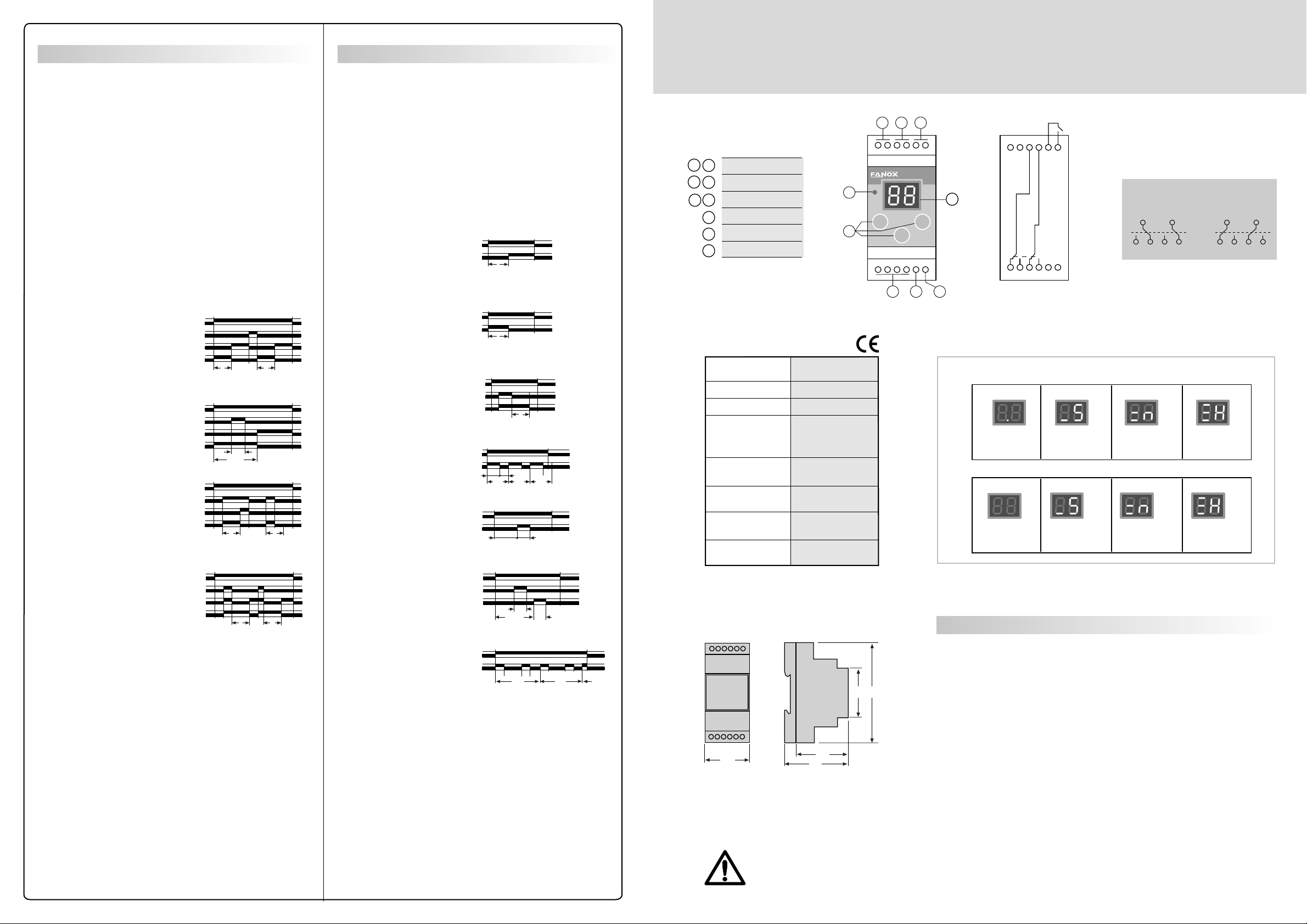
Command contact
Function examples diagrams
MULTIFUNCTION DIGITAL TIMER MTR 10
Can be switched in two ways:
• By closing an external voltage free contact between M and S.
• By connecting 5-35 Vac,dc between M(+) and R(-)
Each diagram represents the effet of the command contact for
the two initial states of the output relay: de-energized (1L) and
energized (1H).
U: power supply
Switched off contact. Its
cu
function is blocked.
Su función está inhibida
Reset contact
cr
When connected the output
relay is de-energized upon
disconnecting, the programmed
timing starts.
Lock contact
cl
A partial shutdown of the timing
takes place during its operation.
ci
Delay on contact
When disconnected the output
relay is de-energized; when
connected the programmed
timings starts.
U
cr
1L
1H
U
cl
1L
1H
U
ci
1L
1H
T T
Tl
T+Tl
T T
U: power supply
R: output relay
Output relay at start: 1L de-energized; 1H energized.
Work mode: CO non-cycle; C1 cycle.
Command contact: cu, cr, cl, ci, co.
Delay ON
1L - CO - cu
Timing ON
1H - CO - cu
Delay OFF with
command contact
1H - CO - co
Double timing
1L - CO - cu
Double timing cycle
work mode
1H - C1 - cu
U
R
T
U
R
T
U
co
R
U
R
T1 T2
C1 C2 C3
U
R
T
T1 T2
2
Auxiliary supply
1
4
3
Command contact
5
Output contact
6
Display
7
Red LED: energized output relay
8
Programmation push-button
9
Technical data
Auxiliary supply 230V 50/60 Hz / 8VA
+15-10% / Consumption 24V Vdc.ac / 1W
Accuracy 1% ± 10 ms
Repeat accuracy 0,5%
Output contacts: C300 - 125/250V
1 relay with 2 timed AC15 - 250V - 2A
change over contacts DC13 - 30V - 2A
NO-NC DC13 - 115V - 2A
Terminals: max section / 2,5mm2, No.22 - 12AWG/
screw torque 20 Ncm, 1,8 LB - IN
Mechanical / >20 x 106 OP /
electrical life 105 OP
Protection degree / IP40 front /
weight
Storage / -30ºC +70ºC /
operation temperature -20°C +55°C
0,15 kg
8
9
Ith= 5 A
1 5 3
R
PROG
I II
OK
6 4 2
MTR 10
A1 A3 15 25
S M
A1 - A2: 230 Vac (+15-10%)
A2 - A3: 24 Vac, cc (+15-10%)
7
16 18 26 28 R A2
ON
15 25
16 18 26 28
TIMES RANGES: THREE (seconds, minutes and hours)
[s]
0.1 ÷ 9.9 s
[s]
1 ÷ 99 s
0.1 ÷ 9.9 m
[m]
1 ÷ 99 m
OUTPUT RELA Y
[m]
0.1 ÷ 9.9 h
1 ÷ 99 h
OFF
15 25
16 18 26 28
[h]
[h]
co
Delay off contact
When disconnected the output
relay is de-energized. When
connected, the relay is
energized. When disconnected
again, the programmed timings
starts.
U
co
1L
1H
T T
Four timings cycle
work mode
1H - C1 - cu
Timing with
partial shutdown
by command contact
1L - CO - cl
U
cl
R
U
R
Tl
T2
T1+Tl
T1 T2 T3 T4
C1 C2 C3
Dimensions
PROGRAMMABLES PARAMETERS
1º Initial state of output relays:
energized (1H) or de-energized (1L).
9045
2º Working mode: cycle (C1) or non-cycle (CO).
3º Number of different times per program: up to 8 in cycle mode
and up to 9 in non-cycle.
4º Time setting range: from 0,1 seconds to 99 hours.
35
53
58
5º Command contact.
With built-in battery which allows timer to be programmed
without connecting to auxiliary voltage.
• ATTENTION: To prevent electrical shock, disconnect from power source before installing or servicing.
• Check that the auxiliary voltage supply is correct.
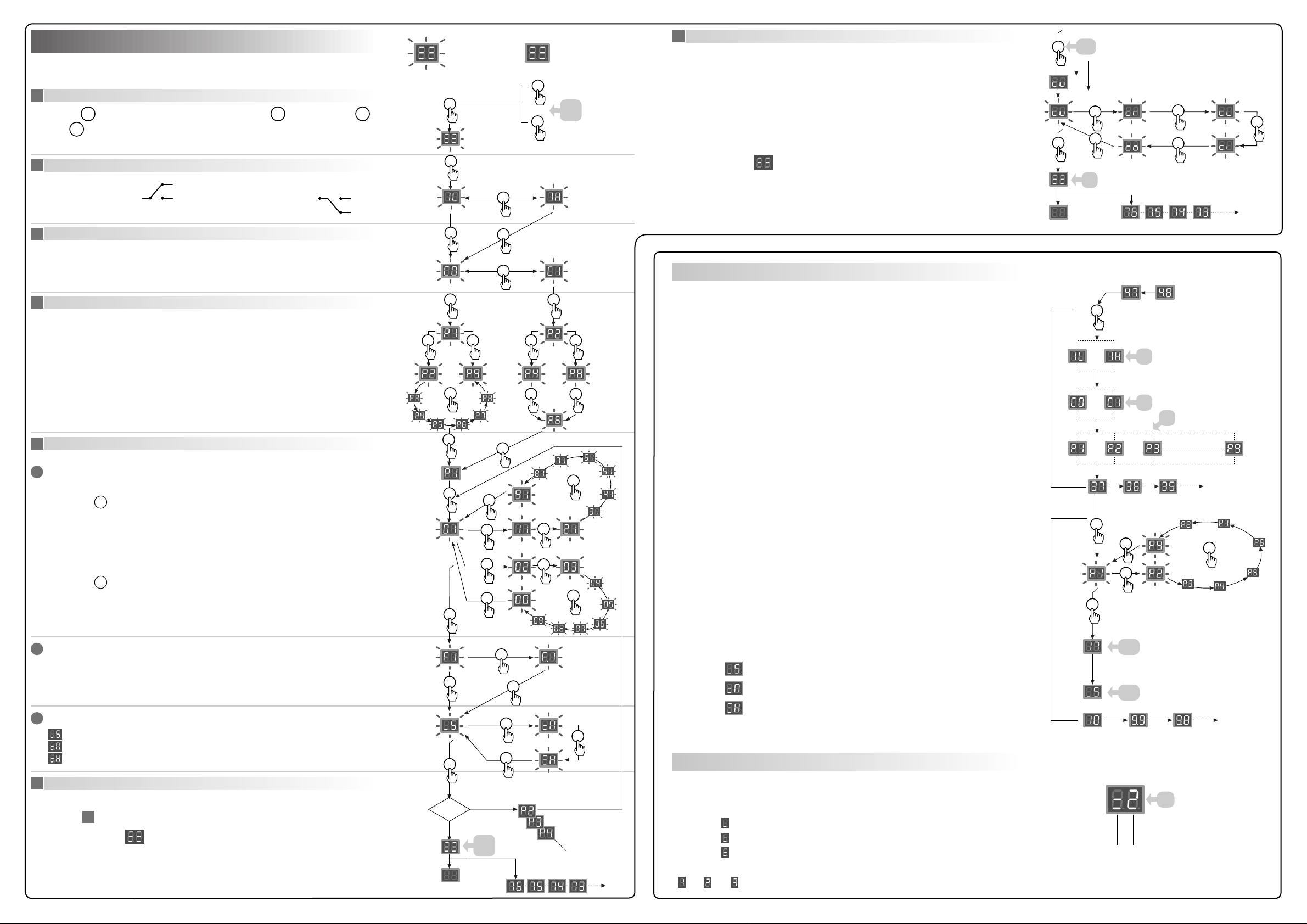
Programmation
Programmation
The built-in battery allows timer to be programmed without connecting
to auxiliary voltage.
Start
1
Hold down OK, and in less than 4 seconds, first push I and then push II.
Release
2
1L: de-energized "0"
3
OK
Initial state of output relay
15/25
Working mode
16/26
18/28
1H: energized "1"
15/25
16/26
18/28
CO: non cycle
C1: cycle
Display
Flashing
OK
OK
OK
Command contact
I
II
Display
Permanent
<4s
7
At the end of programmation, select command contact mode.
Hold down OF for 10s.
The programmed mode is shows in 5s. The timer is supplied with cu (function
blocked).
OK
10s
5s
10s
II
OK
II
II
II
II
The display shows during 4s and then:
– Programmation with battery:
II
Its turns off.
– Programmation with auxiliary voltage:
The program starts.
OK
II
Review of the programmed settings
4s
OFF
Number of timings
4
Non cycle mode (CO)
1, 2, 3, 4, 5, 6, 7, 8 or 9
Cycle mode (C1)
2, 4, 6 or 8
Time settings
5
5.1
Digits
Left digit
Right digit
5.1
5.1
I
II
OK OK
II II II II
II
OK
OK
OK
I
I
II
II
II II
OK
I
II
With timer working. Timing does not stop.
I
- The initial state of output relay is showed for 3s: 1L or 1H
- The working cycle is showed for 3s: CO or C1
3s
3s
3s
- The number of timings is showed for 3s.
• Non cycle mode CO.
1, 2, 3, 4, 5, 6, 7, 8 or 9
I
- Present timing time is showed.
- Programmed value per timing.
• Select the timing number.
II
• Cycle mode C1
2, 4, 6 or 8
OK
II
II
II
II
• Programmed time value.
5.2
Conversion factor
F1: without decimal point (x1)
F.1: with decimal point (x0,1)
5.3
Unit
: seconds
: minutes
: hours
End of timing
6
¿Last timing?
• NO: go to
5
• YES: display shows for 4s and then:
– Programmation with battery:
Its turns off.
– Programmation with auxiliary voltage:
The program starts.
II
• Time unit:
3,5s
Seconds:
OK
OK
Minutes:
3,5s
Hours:
II
II
OK
II
Present timing time is showed.
Timing monitoring
Nearly each 10s information about the number of timings in curse and the display time
NO
unit appears for 2s.
2s
• First digit:
<4s
OFF
seconds
minutes
hours
• Second digit: timing number.
1ª, 2ª, 3ª, ...
e.g.
[m]
nd
2
 Loading...