

FANOX DM30, D30 User Manual
• RELÉ DIFERENCIAL DE FALLOS A TIERRA
• EARTH FAULT DIFFERENTIAL RELAY
1
2
9
8
7
5
6
3
10
1
11
12
4
13
2
3
4
5
6
7
8
9
10
11
12
13
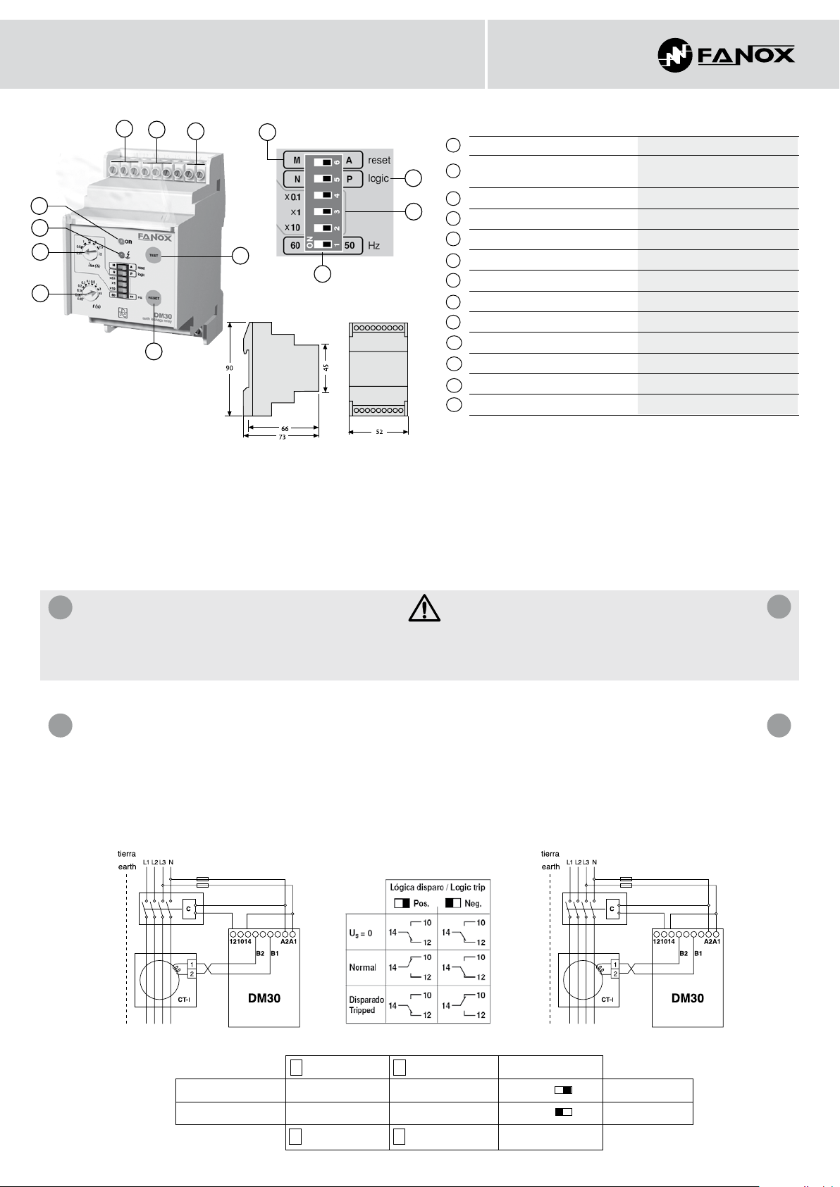
DM30
Contactos de salida
Bornas conexión transformador
toroidal CT-1
Botón de rearme
Botón de prueba
Ajuste sensibilidad
Ajuste del tiempo de retardo
LED rojo, indicación de disparo
LED verde, indicación de alimentación
Alimentación
Tipo de rearme
Selección lógica de disparo
Factor multiplicador de
Selección frecuencia de la red
∆n
I
∆n
I
Output contacts
Connection terminals for toroidal
transformer CT-1
Reset push-button
Test push-button
Sensitivity adjustment
Delay time adjustment
Red LED, trip indication
Green LED, supply indication
Supply
Reset type
Logic trip selection
∆n
multiplier factor
I
Network frequency selection
∆n
I
El relé supervisa permanentemente el circuito toroidal-relé, si este se
*
interrumpe el relé dispara y enciende de forma intermitente el LED rojo.
El equipo dispone de doble circuito de medida lo que le confiere una
**
seguridad redundante. Si uno de estos circuitos se averiase el relé
seguiría midiendo correctamente por el otro. Esta situación es detectada
por la función auto-diagnostico de que dispone y señalizada mediante el
parpadeo del LED verde ON. Cuando se de esta improbable situación es
aconsejable sustituir el relé cuando sea posible.
INSTRUCCIONES DE SEGURIDAD
A
• Para evitar descargas eléctricas durante la instalación o manipulación del
relé, asegúrese de que no hay tensión en la línea ni tensión auxiliar.
• Comprobar que la tensión nominal es la correcta.
ESQUEMA DE CONExIONES
B B
• Cableado: Los esquemas se representan con el relé sin tensión de
alimentación.
• Conectar el dispositivo de disparo (bobina de emisión, bobina de
mínima, contactor, etc.) según el siguiente cuadro.
The relay constantly supervises the toroidal circuit-relay. Should this
*
become interrupted the relay trips and the red LED begins to flash.
The unit is equipped with a double measuring circuit providing
**
redundant safety. Should one of these circuits fail, the relay shall
continue measuring correctly via the other one. This situation is detected
by its self-diagnosis function and is signalled by means of the flashing
green LED ON. Should this improbable situation occur it is advisable to
replace the relay as soon as possible.
SAFETY INSTRUCTIONS
• To prevent electric discharges during the installation or handling of the
relay, ensure there is no voltage in the line and no auxiliary voltage.
• Check that the nominal voltage is correct.
CONNECTION DIAGRAM
• Wiring: The schematics show the relay with supply voltage disconnected.
• Connect the trip device (shunt trip coil, undervoltage trip coil, contactor,
etc.) according to the following table.
A
Fig. 1 Fig. 2
- Bobina de mínima
C
- Contactor
Prioridad de seguridad Fig. 2 Fig. 1 Posit. P Safety priority
Prioridad de servicio
Fig. 1 Fig. 2 Negat. N Service priority
-
Undervoltage trip coil
C C
- Contactor
- Bobina de emisión Lógica de disparo
C
- Shunt trip coil Logic trip
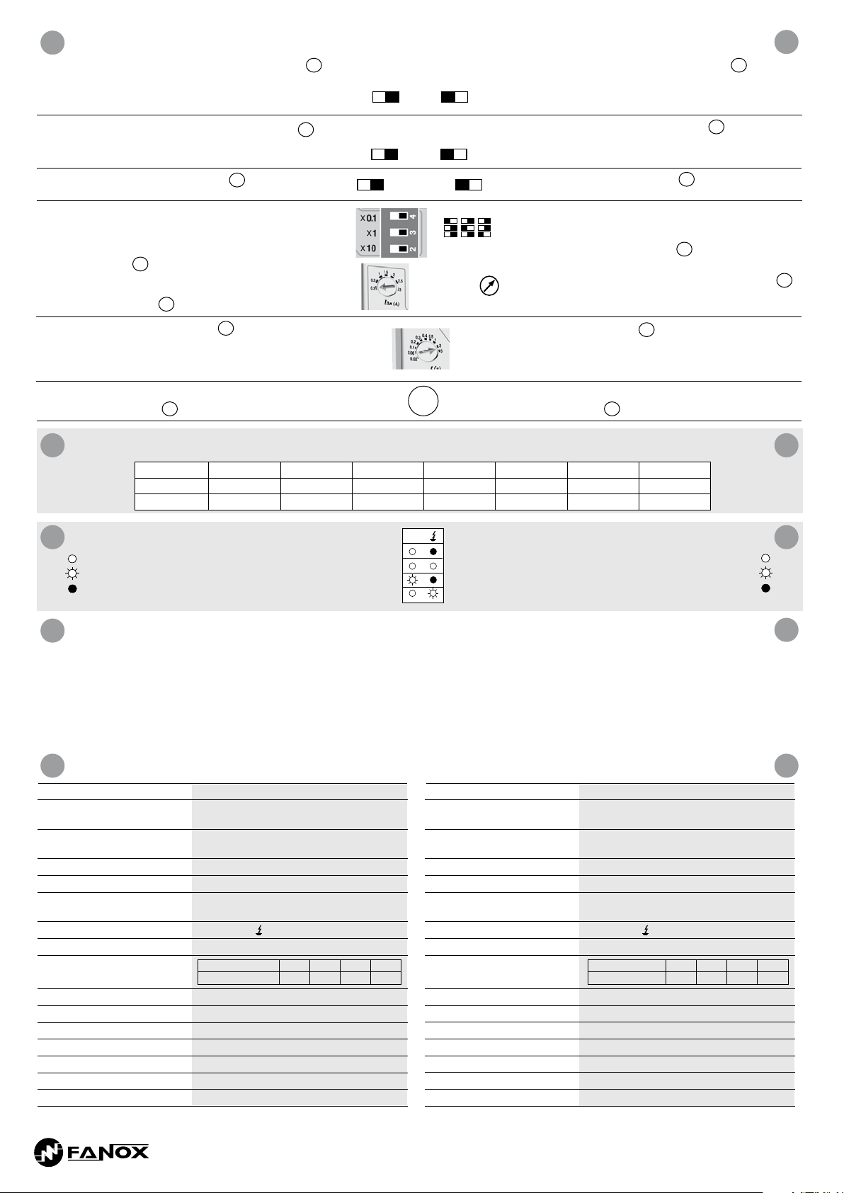
AjUSTES
C
1. Seleccionar el tipo de rearme: automático o manual. 3
10
Para realizar el rearme manual pulsar el RESET. Con
rearme manual se puede realizar el rearme a distancia
quitando la alimentación auxiliar durante 1 segundo.
2. Seleccionar lógica de disparo positiva o negativa.
3. Seleccionar la frecuencia de la red.
13
11
Rearme automático
Automatic reset
M A M A
Lógica positiva
Positive logic
N P N P
60 Hz 50 Hz 60 Hz 50 Hz
Rearme manual
Manual reset
Lógica negativa
Negative logic
SETTINGS
1.
Select the reset type: automatic or manual. For
manual
reset press RESET. The manual resetting can
10
be performed remotely removing the auxiliary supply
for 1 second.
2. Select positive or negative trip logic.
3. Select the network frequency.
11
13
C
4. Ajustar la sensibilidad
∆n
:
I
Seleccionar el factor multiplicador con los tres
correspondientes conmutadores deslizantes, este
factor se aplicará al valor que seleccionamos con el
potenciómetro.
12
Ajustar la intensidad de disparo mediante el
correspondiente potenciómetro teniendo en cuenta el
factor seleccionado.
5. Seleccionar el tiempo de retardo.
Si se ha seleccionado
siempre será instantáneo, independientemente de la
5
6
∆n
=30mA el disparo
I
∆n = factor x
I
4. Adjust sensitivity
Select the multiplier factor with the three corresponding
x 10x 1x 0,1
dipswitches. This factor shall be applied to the value we
select with the potentiometer.
Adjust the trip current by means of the corresponding
potentiometer bearing in mind the selected factor.
5. Select the delay time.
∆n
If
=30mA is selected the trip shall always be
I
immediate, regardless of the time selected.
∆n
:
I
12
6
temporización que hayamos seleccionado.
6. Cuando se conecte la instalación es obligatorio realizar
un TEST con disparo.
Con el n de evitar disparos intempestivos, es recomendable que el valor de corriente de fuga ajustado no sea inferior a los denidos en la siguiente tabla:
D D
In order to avoid unexpected trips, it is recommended that the value of the adjusted leakage current value not be lower than the values shown in the following
table:
SEñAlIzACIóN
E E
Encendido
Intermitente
Apagado
4 4
Tipo / Type CTD-1/28 CT-1/35 CT-1/60 CT-1/80 CT-1/110 CT-1/160 CT-1/210
CT Ø 28 mm 35 mm 60 mm 80 mm 110 mm 160 mm 210 mm
Min. I∆n 30 mA 30 mA 30 mA 100 mA 250 mA 250 mA 250 mA
Normal, relé alimentado
Disparado, fuga a tierra
Autodiagnóstico, error (ver **)
Disparado, mala conexión con toroidal
LED’s
TEST
LED’s
ON
Normal, relay ON
Tripped, earth fault
Self-checking error (see **)
Check transformer line
6. When the installation is connected a TEST with trip must
be performed.
SIGNAlS
ON
flashing
OFF
5
TEST
F
1. TEST con disparo: al pulsar el boton TEST el equipo dispara y se enciende
el LED rojo.
2. TEST sin disparo: si se pulsa el boton de RESET y manteniéndolo se
pulsa el TEST el relé no disparará pero se encenderá el LED rojo,
permaneciendo encendido mientras mantengamos pulsados los dos
botones. Para nalizar el ensayo y evitar que el relé dispare dejar de pulsar
primero el TEST y después el RESET.
TEST
1. TEST with trip: on pressing the TEST button the unit trips and the red LED
lights up.
2. TEST without trip: If you press the RESET button and, whilst it is maintained,
the TEST button is pressed, the relay will not trip but the red LED will light
up, remaining light whilst both buttons are pressed. To end the TEST and
prevent the relay from tripping, release the TEST push-button first and then
the RESET push-button.
CARACTERíSTICAS TéCNICAS TEChNICAl ChARACTERISTICS
Sensibilidad Regulable de 0,03 A a 30 A
Retardo a la desconexión Regulable de 0,02 s a 5 s (10 valores).
Disparo instantáneo si I∆n = 30 mA
Tensión auxiliar 230 Vca ± 15% 50/60 Hz
120 Vca ± 15% 50/60 Hz
Frecuencia de la corriente a controlar 50/60 Hz
Transformador toroidal CT-1
Rearme seleccionable Automático, manual y remoto (en posición manual
Señalización 2 LED’s: ON +
Modo relé salida. Lógica disparo
Máx. longitud de cable entre relé
y transformador
Contactos de salida 1 conmutado NA-NC
Poder de corte I
Terminales: sección máxima 2,5 mm
Consumo 2,5 VA (120-230Vca)
Grado de protección / peso IP-20 / 0,2 kg
Temperatura de funcionamiento -10°C +60°C
Normas
desconectar la tensión auxiliar durante 1s)
Seleccionable normalmente no energizado (N) / energizado (P)
Sección cable mm20,22 0,75 1 1,5
Longitud máxima m 15 55 75 110
: 5A; AC15 - 250V - 2A; DC13 - 30V - 2A
th
2
EN 60947-2-B,EN 50263,EN61543 (A11), IEC60255-5, VDE 0664
Sensitivity Adjustable from 0,03 A to 30 A
Trip time delay Adjustable from 0,02 s to 5 s (10 values).
Instant trip if I∆n = 30 mA
Aux. voltage supply 230 Vac ± 15% 50/60 Hz
120 Vac ± 15% 50/60 Hz
Frequency 50/60 Hz
Toroidal transformer CT-1
Reset mode Automatic, manual and remote (in manual mode
Signalling LED’s 2 LED’s: ON +
Output contacts mode. Trip logic
Max. cable length between relay
and transformer
Output contacts 1 change over NO-NC
Switching power I
Maximum terminal section 2,5 mm
Consumption 2,5 VA (120-230Vac)
Protection degree / weight IP-20 / 0,2 kg
Storage / operation temperature -10°C +60°C
Standards
disconnect the aux. supply during 1s)
Selectable: normally de-energized (N) / or energized (P)
Cable section mm20.22 0.75 1 1.5
Max. lenght m 15 55 75 110
: 5A; AC15 - 250V - 2A; DC13 - 30V - 2A
th
2
EN 60947-2-B,EN 50263,EN61543 (A11), IEC60255-5, VDE 0664
F
GG
Tel.: (+34) 94 471 14 09 - Fax.: (+34) 94 471 05 92
www.fanox.com fanox@fanox.com
02/2012/D00
FANOX se reserva el derecho de efectuar cualquier modificación de las
características señaladas en este documento sin necesidad de previo aviso.
Fanox reserves the right to modify technical specification of products
contained within this document without previous notice.
 Loading...