

Page 1
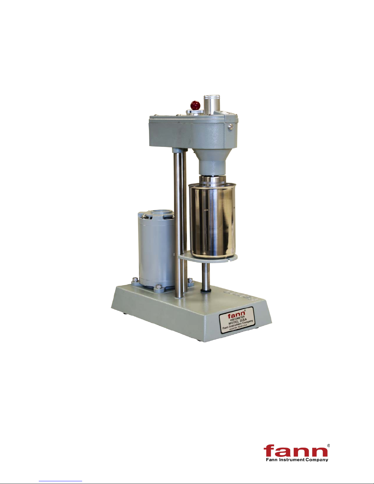
Model 35 Viscometer
Instruction Manual
Models 35A, 35SA, 35A/SR-12, and 35SA/SR-12
Manual No. 208878, Revision N
Page 2
Model 35 Instruction Manual
©2013 Fann Instrument Company
Houston, Texas, USA
All rights reserved. No part of this work covered by the copyright hereon may be reproduced or
copied in any form or by any means (graphic, electronic, or mechanical) without first receiving the
written permission of Fann Instrument Company, Houston, Texas, USA.
Printed in USA.
The information contained in this document includes concepts, methods, and apparatus
which may be covered by U.S. Patents. Fann Instrument Company reserves the right to
make improvements in design, construction, and appearance of our products without prior
notice
®
FANN
States and/or other countries. All other trademarks mentioned in the operating instructions are the
exclusive property of the respective manufacturers.
and the FANN logo are registered trademarks of Fann Instrument Company in the United
Contact FANN
Phone
TELEPHONE: 281-871-4482
TOLL FREE: 800-347-0450
FAX: 281-871-4358
Mail
Fann Instrument Company
P.O. Box 4350
Houston, Texas, 77210 USA
Location
Fann Instrument Company
15112 Morales Rd Gate 7
Houston, Texas, 77032, USA
Online
www.fann.com
[email protected]
208878 Revision N, February 2013 2
Page 3

Model 35 Viscometer Instruction Manual
Table of Contents
1 Introduction ............................................................................................................... 5
1.1 Background ...................................................................................................... 5
1.2 Document Conventions .................................................................................... 6
2 Safety ....................................................................................................................... 7
2.1 Safe Electrical Operation .................................................................................. 7
2.2 Standard B1 Bob .............................................................................................. 8
2.3 Heated Sample Cup ......................................................................................... 8
3 Features and Specifications ...................................................................................... 9
4 Installation .............................................................................................................. 13
5 Operation ................................................................................................................ 14
5.1 Operating the Model 35A and 35SA ............................................................... 15
5.2 Operating the Model 35A/SR-12 and 35SA/SR-12.......................................... 15
5.3 Measuring Gel Strength .................................................................................. 17
5.4 Changing the Rotors, Bobs, and Torsion Springs ........................................... 18
6 Instrument Calibration Check .................................................................................. 23
6.1 Dead Weight Calibration ................................................................................. 24
6.2 Fluid Calibration Check ................................................................................... 26
6.3 Torsion Spring Calibration .............................................................................. 27
7 Test Analysis .......................................................................................................... 28
7.1 Newtonian Viscosity Calculation ..................................................................... 28
7.2 Plastic Viscosity and Yield Point Calculation ................................................... 29
7.3 Spring Constant Calculation ........................................................................... 30
7.4 Additional Viscosity Calculations ..................................................................... 31
7.5 Measuring Ranges .......................................................................................... 33
8 Troubleshooting and Maintenance .......................................................................... 36
8.1 Troubleshooting .............................................................................................. 36
8.2 Maintenance ................................................................................................... 37
9 Accessories ............................................................................................................ 38
10 Parts List................................................................................................................. 39
11 Warranty and Returns ............................................................................................. 44
11.1 Warranty ......................................................................................................... 44
11.2 Returns ........................................................................................................... 44
208878 Revision N, February 2013 3
Page 4

Model 35 Viscometer Instruction Manual
List of Figures
Figure 3-1 Model 35SA Viscometer ................................................................................. 9
Figure 3-2 Model 35 Viscometer Schematic .................................................................. 10
Figure 5-1 Gear Box Shift Lever .................................................................................... 16
Figure 5-2 Rotor Removal and Installation .................................................................... 19
Figure 5-3 Bob and Bob Shaft ....................................................................................... 20
Figure 5-4 Torsion Spring Removal and Replacement .................................................. 22
Figure 6-1 DW3 Calibration Fixture ............................................................................... 24
Figure 10-1 Model 35A and 35SA - Upper ..................................................................... 40
Figure 10-2 Model 35A and 35SA – Lower .................................................................... 41
List of Tables
Table 3-1 Model 35 Viscometer Specifications .............................................................. 11
Table 3-2 Model 35 Viscometer Sizes ........................................................................... 11
Table 3-3 Rotor and Bob Dimensions ............................................................................ 12
Table 3-4 Rotor-Bob Specifications ............................................................................... 12
Table 3-5 Range of Environmental Conditions .............................................................. 12
Table 5-1 Six-Speed Testing Combinations for Models 35A and 35SA ......................... 15
Table 5-2 Twelve-Speed Testing Combinations- Models 35A/SR-12 and 35SA/SR-12 . 16
Table 6-1 Dial Deflection for Calibration Weights and Torsion Spring Assemblies ......... 25
Table 7-1 Rotor-Bob Factor (C) ..................................................................................... 29
Table 7-2 Speed Factor (S) ........................................................................................... 29
Table 7-3 Torsion Spring Specifications ........................................................................ 30
Table 7-4 Constants for Viscosity Calculations .............................................................. 32
Table 7-5 Conversion Factors ....................................................................................... 32
Table 7-6 Shear Stress Measuring Range for Fann Direct Indicating Viscometer .......... 33
Table 7-7 Shear Rate Measuring Range for Fann Direct Indicating Viscometers .......... 34
Table 7-8 Viscosity Range in Centipoise for Fann Direct Indicating Viscometers .......... 35
Table 8-1 Troubleshooting Guide .................................................................................. 36
Table 9-1 Accessories ................................................................................................... 38
Table 10-1 Model 35 Series Viscometers ...................................................................... 39
Table 10-2 Model 35 Series Viscometer Parts List ........................................................ 42
208878 Revision N, February 2013 4
Page 5

Model 35 Viscometer Instruction Manual
1 Introduction
Fann Model 35 viscometers are direct-reading instruments which are available in
six- speed and twelve- speed designs for use on either 50 Hz or 60 Hz electrical
power. The standard power source is 115 volts, but all models may be fitted with a
transformer, making operation with 220/230 volts possible.
Fann Model 35 viscometers are used in research and production. These viscometers
are recommended for evaluating the rheological properties of fluids, Newtonian
and non-Newtonian. The design includes a R1 Rotor Sleeve, B1 Bob, F1 Torsion
Spring, and a stainless steel sample cup for testing according to American
Petroleum Institute Recommended Practice for Field Testing Water Based Drilling
Fluids, API RP 13B-1/ISO 10414-1 Specification.
1.1 Background
Fann Model 35 viscometers are Couette rotational viscometers. In this viscometer,
the test fluid is contained in the annular space (shear gap) between an outer cylinder
and the bob (inner cylinder). Viscosity measurements are made when the outer
cylinder, rotating at a known velocity, causes a viscous drag exerted by the fluid.
This drag creates a torque on the bob, which is transmitted to a precision spring
where its deflection is measured.
Viscosity measured by a Couette viscometer, such as the Model 35, is a measure of
the shear stress caused by a given shear rate. This relationship is a linear function
for Newtonian fluids (i.e., a plot of shear stress vs. shear rate is a straight line).
The instrument is designed so that the viscosity in centipoise (or millipascal
second) of a Newtonian fluid is indicated on the dial with the standard rotor R1,
bob B1, and torsion spring F1 operating at 300 rpm. Viscosities at other test speeds
may be measured by using multipliers of the dial reading. A simple calculation that
closely approximates the viscosity of a pseudo-plastic fluid, such as a drilling fluid
is described in Section 7.
The shear rate may be changed by changing the rotor speed and rotor-bob
combination. Various torsion springs are available and are easily interchanged in
order to broaden shear stress ranges and allow viscosity measurements in a variety
of fluids.
208878 Revision N, February 2013 5
Page 6
Model 35 Viscometer Instruction Manual
1.2 Document Conventions
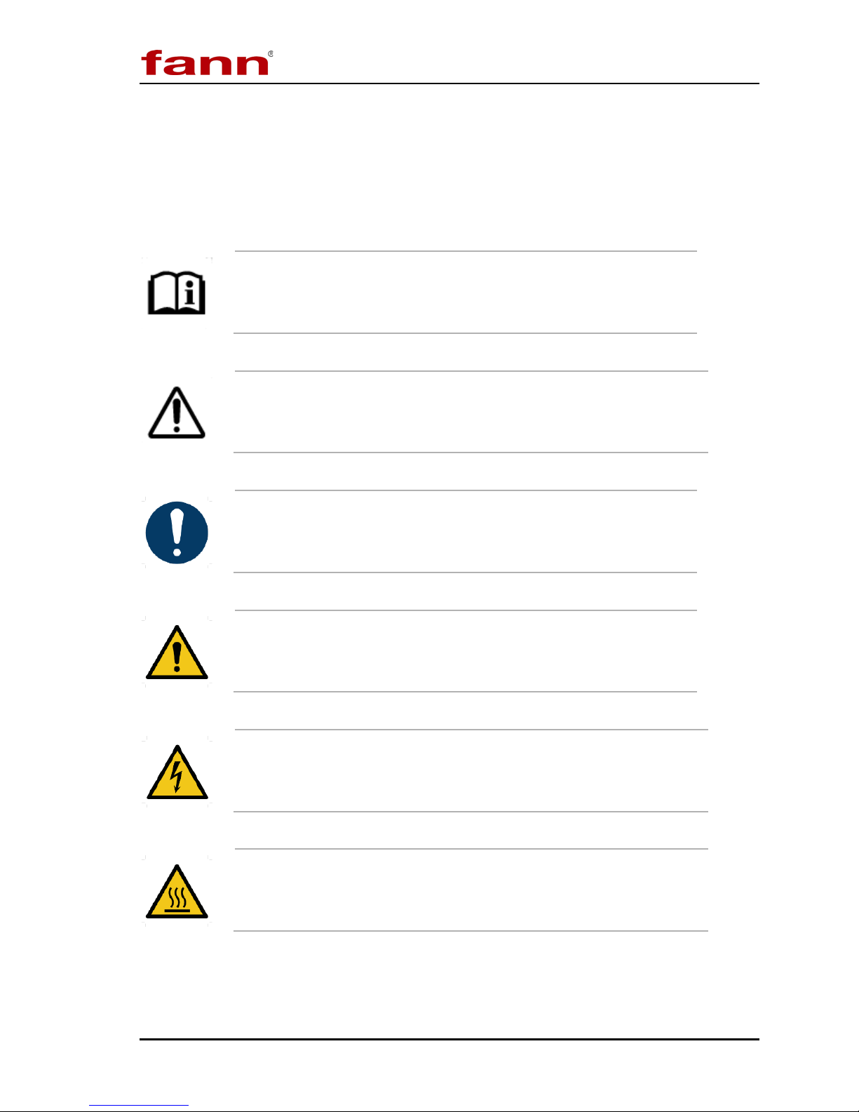
The following icons are used as necessary to distinguish elements of text.
NOTE. Notes emphasize additional information that may be
useful to the reader.
CAUTION. Describes a sit uat ion or practice that requires operator
awareness or action in order to avoid undesirable consequences.
MAN D AT O R Y AC TION . Gives directions that, if not observed,
could result in loss of data or in damage to equipment.
WARNING! Describes an unsafe condition or practice that if not
corrected, could result in personal injury or threat to health.
ELECTRICITY WARNING! Alert s t he operator that there is risk of
electric shock.
HOT SURFACE! Alerts the operator that there is a hot surface and
that there is risk of getting burned if the surface is touched.
208878 Revision N, February 2013 6
Page 7
Model 35 Viscometer Instruction Manual
2 Safety
Safe laboratory practices and procedures should be observed while operating and
maintaining the Model 35 viscometer.
The safe operation of the Fann Model 35 series viscometer requires that the
laboratory technician be familiar with the proper operating procedures and potential
hazards associated with the instrument.
The operator should be properly trained before operating this equipment. The safe
operation of this equipment may be impaired if it is used in a manner not specified
by the manufacturer.
2.1 Safe Electrical Operation
This instrument is driven by 115 volt or 230 volt electrical power. Keep hands,
clothes and other objects away from the rotating parts of the machine.
The optional heated sample cups and recirculating sample cups are electrically
heated. Make sure the power cord and other wiring associated with these cups and
the Model 35 assembly is in good condition and properly grounded.
Make sure the viscometer’s power switch is the OFF position and unplugged from
the source before cleaning, repairing or performing maintenance.
Please note that when motor speed /control power switch is in the
OFF position, power is only removed from the motor. However, the
power switch and the capacitor wil still have a charge.
Do not allow the viscometer base to get wet. If samples have been spilled or
splattered, wipe clean with a damp cloth. Do not allow water to run into the base;
excessive water could cause damage to the electrical components.
208878 Revision N, February 2013 7
Page 8
Model 35 Viscometer Instruction Manual
2.2 Standard B1 Bob
The standard B1 bob (furnished with the Model 35 series
viscometers) is a hollow bob that must not be used to test
samples hotter than 200°F (93°C).
Solid bobs are available for testing at higher temperatures.
2.3 Heated Sample Cup
When testing heated samples using the heated sample cups
wear the proper hand protection to avoid getting burned.
When using heated sample cups, do NOT exceed 200oF (93oF).
208878 Revision N, February 2013 8
Page 9
Model 35 Viscometer Instruction Manual
3 Features and Specifications
The Fann direct-indicating viscometers are equipped with the standard R1 rotor
sleeve, B1 bob, F1 torsion spring, and a stainless steel sample cup. Other rotor-bob
combinations and/or torsion springs can be substituted to extend the torque
measuring range or increase the sensitivity of the torque measurement.
Each viscometer is supplied with a 115 volt motor. For operation on 230 volts, a
step-down transformer is required.
The viscometers are available in six-speed and twelve-speed models.
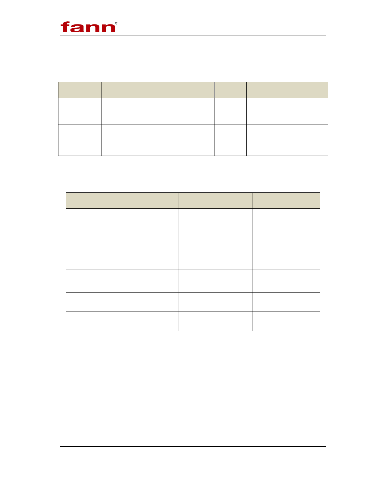
See Table 3-1, 3-2, 3-3, and 3-4 for specifications. Table 3-5 lists the recommended
environmental conditions for use.
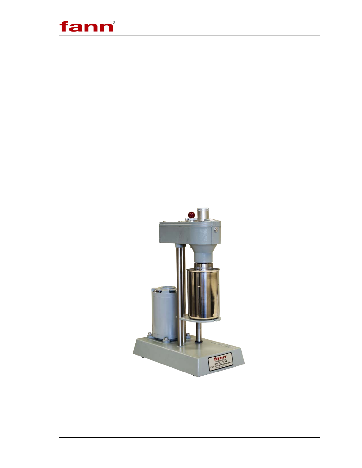
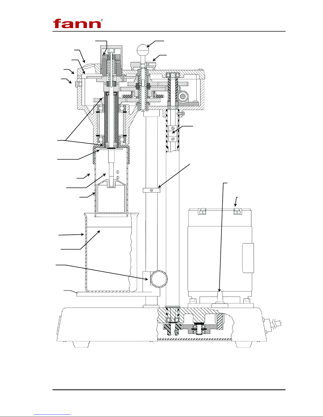
Figure 3-1 is a picture of the viscometer and Figure 3-2 is a detailed drawing that
names the individual parts.
208878 Revision N, February 2013 9
Figure 3-1 Model 35SA Viscometer
Page 10
Model 35 Viscometer Instruction Manual
Switch
Lens
Gas Purge Nipple
Bob Shaft
Bob
Sample Fill Line
Locking Knob
Stage
Torsion Spring Assembly
Pointer
(optional)
Bearings
Splash Guard
Bob Shaft
Gear Shift Knob
Gel Knob
Dial
Coupling
Stop
Scribed Line
Motor Speed
Circulating Cup
(350 ml)
2 Speed Motor
208878 Revision N, February 2013 10
Figure 3-2 Model 35 Viscometer Schematic
Page 11
Model 35 Viscometer Instruction Manual
Dimensions
(LxDxH)
39 x 15 x 27 cm
6.8 kg
39 x 15 x 27 cm
6.8 kg
20.3 x 40.6 x 48.3 cm
11.8 kg
20.3 x 40.6 x 48.3 cm
11.8 kg
No. of
Speeds
600, 300, 200, 180, 100,
90, 60, 30, 6, 3, 1.8, 0.9
600, 300, 200, 180, 100,
90, 60, 30, 6, 3, 1.8, 0.9
Table 3-1 Model 35 Viscometer Specifications
Model No. Part No. Electrical
35A 207198
35SA 207199
35A/SR-12 207200
35SA/SR-12
207201
115V, 60 Hz, 90W
115V, 50 Hz, 90W
115V, 60 Hz, 90W
115V, 50 Hz, 90W
Table 3-2 Model 35 Viscometer Sizes
Model No. Part No.
35A 207198
35SA 207199
15.2 x 6 x 10.5 in.
15.2 x 6 x 10.5 in.
15.2 x 6 x 10.5 in.
35A/SR-12 207200
6 600, 300, 200, 100, 6, 3
6 600, 300, 200, 100, 6, 3
12
12
39 x 15 x 27 cm
Speeds
Weight
15 lb
15 lb
15 lb
6.8 kg
35SA/SR-12 207201
35A w/ case 101671768
35SA w/ case 101671770
15.2 x 6 x 10.5 in.
39 x 15 x 27 cm
8 x 16 x 19 in.
8 x 16 x 19 in.
15 lb
6.8 kg
26 lb
26 lb
208878 Revision N, February 2013 11
Page 12
Model 35 Viscometer Instruction Manual
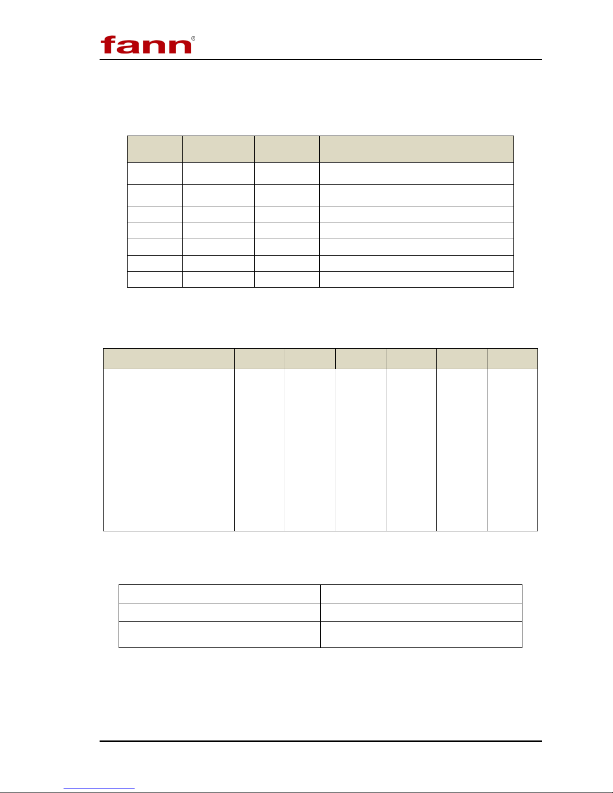
Radius
(cm)
Length
(cm)
3.8
1.9
n/a
n/a
n/a
80% RH at 87.8oF (31oC) or les s
50% RH at 104oF (40oC)
Table 3-3 Rotor and Bob Dimensions
Unit
B1 1.7245
B2 1.2276
B3 0.86225
B4 0.86225
R1 1.8415
R2 1.7589
R3 2.5867
3.8
3.8
Cylinder Area (cm2) x Radius (cm)
71.005
35.981
17.751
8.876
n/a
n/a
n/a
Table 3-4 Rotor-Bob Specifications
ROTOR-BOB R1 B1 R2 B1 R3 B1 R1 B2 R1 B3 R1 B4
Rotor Radius, R0 (cm) 1.8415 1.7588 2.5866 1.8415 1.8415 1.8415
Bob Radius, Ri (cm) 1.7245 1.7245 1.7245 1.2276 0.8622 0.8622
Bob Height, L (cm) 3.8 3.8 3.8 3.8 3.8 1.9
Shear Gap in Annulus
(cm)
0.117 0.0343 0.8261 0.6139 0.9793 0.9793
Radii Ratio, Ri /R0 0.9365 0.9805 0.667 0.666 0.468 0.468
Maximum Use
Tempe rature (
Minimum Use
Tempe rature (
o
o
C)
C)
93 93 93 93 93 93
0 0 0 0 0 0
Table 3-5 Range of Environmental Conditions
Maximum Altitude
Temperature Range
6562 ft (2000 m)
o
F to 104oF (5oC to 40oC)
41
Maximum Relative Humidity (RH)
208878 Revision N, February 2013 12
Page 13

Model 35 Viscometer Instruction Manual
4 Installation
The Model 35 should be placed in a position where there is easy access to the
power cord plug for disconnection.
Consideration should be given to the location where samples are prepared and
equipment is cleaned when the test is completed. There should be sufficient storage
area nearby for commonly used tools, as well as consumables.
208878 Revision N, February 2013 13
Page 14
Model 35 Viscometer Instruction Manual
5 Operation
This section describes the operating instructions for the Model 35 series
viscometers. It also includes instructions for measuring gel strength and changing
rotors, bobs, and torsion springs.
To start the test, add 350 ml of pre-stirred sample to the stainless steel sample cup.
The sample cup has a line that marks 350 ml as shown in Figure 3-2.
A scribed line on the rotor indicates proper immersion depth. Refer to Figure 3-2.
Damage to the bob shaft bearings may occur if this immersion depth is exceeded. If
other sample holders are used, the space between the bottom of the rotor and the
bottom of the sample holder should be one-half inch (1.27cm) or greater.
The standard B1 Bob is hollow and should never be used to test
samples hotter than 200
o
F (93oC).
208878 Revision N, February 2013 14
Page 15

Model 35 Viscometer Instruction Manual
5.1 Operating the Model 35A and 35SA
The Model 35A and 35SA viscometers operate at six speeds, ranging from 3 rpm
to 600 rpm. To select the desired speed, set the speed switch (located on the right
side of the base) to the high or low speed position as desired. Then turn the motor
on and move the gear shift knob (located on the top of the instrument) to the
position that corresponds to the desired speed.
Table 5-1 lists the positions for the viscometer switch and the gear knob
combinations to obtain the desired speed. The viscometer gear shift knob may be
engaged while the motor is running. Read the dial for shear stress values.
Table 5-1 Six-Speed Testing Combinations for Models 35A and 35SA
Speed RPM Viscometer Switch Gear Shift Knob
600 High Down
300 Low Down
200 High Up
100 Low Up
6 High Center
3 Low Center
5.2 Operating the Model 35A/SR-12 and 35SA/SR-12
The Model 35A/SR-12 and 35SA/SR-12 have twelve speeds for testing
capabilities. To achieve this broader testing range from 0.9 rpm to 600 rpm, an
additional gear box shift lever is used; it is located on the right side of the gear box.
See Figure 5-1. Move this lever to the left or right as determined from Table 5-2.
Never change the gear box shift lever while the motor is running.
Changing it while the motor is running will result in gear damage
Only the viscometer gear shift knob (on top of the instrument)
can be changed while the motor is running.
208878 Revision N, February 2013 15
Page 16

Model 35 Viscometer Instruction Manual
Gear Box Shift Lever
After preparing the instrument for 12-speed testing by setting the gear box shift
lever, select the proper speed range with the speed shift switch. Then turn on the
motor and set the gear shift knob on the top of the instrument. Refer to Table 5-2
for the correct combination of gear box shift lever setting, speed switch selection,
and viscometer gear shift knob placement. The shear stress values will appear on
the dial.
Figure 5-1 Gear Box Shift Lever
Table 5-2 Twelve-Speed Testing Combinations- Models 35A/SR-12 and 35SA/SR-12
RPM Gear Box
Shift Lever
600 Left High Down
300 Left Low Down
200 Left High Up
180 Right High Down
100 Left Low Up
90 Right Low Down
60 Right High Up
30 Right Low Up
6 Left High Center
3 Left Low Center
1.8 Right High Center
Speed Switch Gear Shift
Knob
0.9 Right Low Center
208878 Revision N, February 2013 16
Page 17

Model 35 Viscometer Instruction Manual
5.3 Measuring Gel Strength
The commonly used procedure for measuring gel strength is as follows:
1. Stir the sample thoroughly at 600 rpm.
2. Set the gear shift knob to the 3 rpm position, and then turn the motor to the OFF
position.
3. After the desired wait time, turn the motor to the ON position at low speed.
4. Read the dial at the moment the gel breaks as noted by a peak dial reading. The
gel strength units are lb/100ft2.
An alternative method for measuring gel strength is as follows:
1. Stir the sample thoroughly at 600 rpm.
2. Turn the motor to the OFF position.
3. After the desired wait period, turn the gel knob (located below the gear shift
knob) slowly counterclockwise.
4. Read the dial at the moment the gel breaks as noted by a peak dial reading. The
gel strength units are lb/100ft2.
208878 Revision N, February 2013 17
Page 18

Model 35 Viscometer Instruction Manual
5.4 Changing the Rotors, Bobs, and Torsion Springs
The R1-B1-F1 rotor-bob-torsion spring combination is standard for all Fann
viscometers. Other rotor-bob combinations may be used, provided shear rates are
calculated for the fluid being tested. Rotor-bob combinations other than R1-B1
have large gap sizes; as a result, the shear stress dial readings are not consistent
with readings from a smaller gap.
The following instructions explain how to remove and replace the rotors, bobs, and
torsion springs.
Calibration is required when torsion springs are changed.
Changing the rotors and bobs only reconfigures the geometry of
the shear gap. These changes do not affect the torsion springs,
bearings, or shaft. Therefore, calibration is not required when
changing rotors or bobs.
208878 Revision N, February 2013 18
Page 19
Model 35 Viscometer Instruction Manual
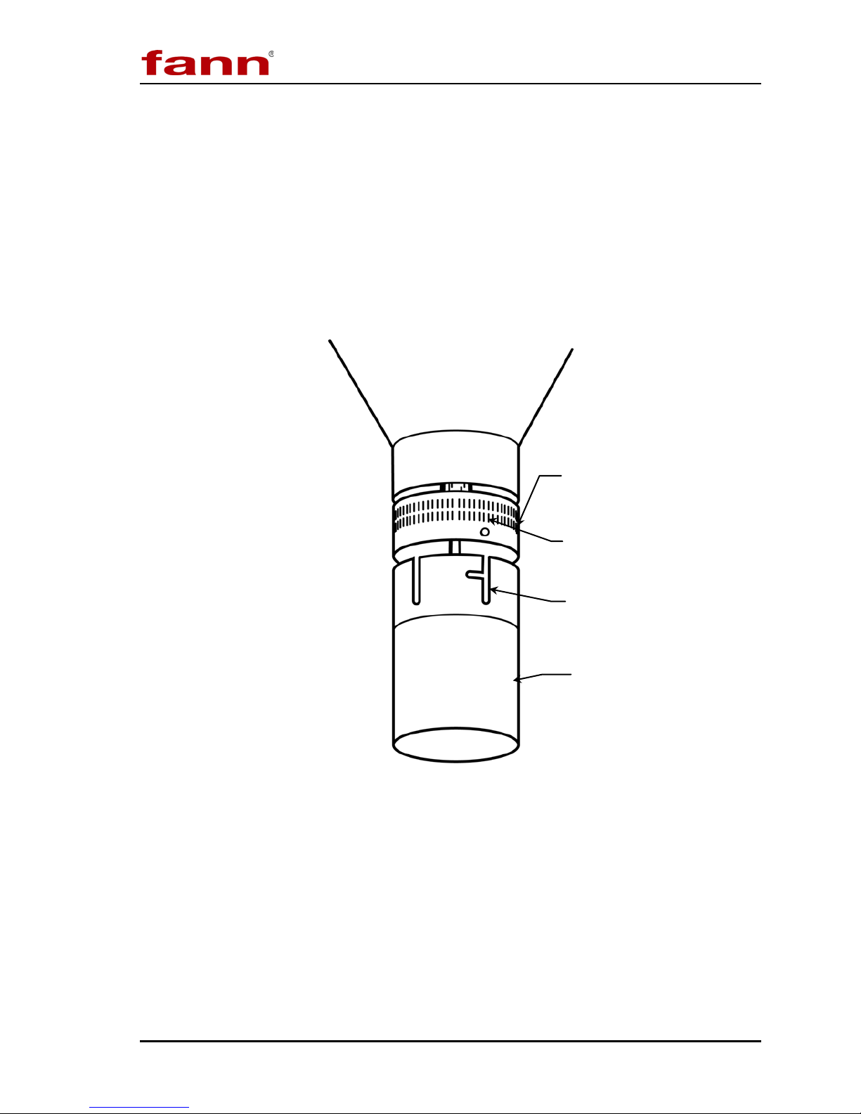
Main Shaft
Lock Pin
Rotor
To remove rotor: Rotate
To replace rotor: Align slot and
turning counterclockwise.
5.4.1 Rotor Removal and Replacement
Refer to Figure 5-2.
To remove the rotor from its socket, twist the rotor clockwise and gently pull it
down.
To replace the rotor, align the rotor slot and groove with the lock pin in the main
shaft socket. Then push the rotor upward and turn it counterclockwise, locking it
into position.
clockwise and pull down.
groove with lock pin, then push
upward
and lock into place by
Figure 5-2 Rotor Removal and Installation
Slot and Groove
208878 Revision N, February 2013 19
Page 20

Model 35 Viscometer Instruction Manual
Bob Shaft
Bob (Type B-1 hollow
5.4.2 Bob Removal and Replacement
The bob shaft end is tapered and fits into a matching tapered hole in the bob. Refer
to Figure 5-3.
1. Rotate the rotor clockwise and gently pull it down to remove it.
2. To remove the bob, twist it clockwise while pulling down.
3. To install the bob, twist it clockwise while pushing upward.
shown
Figure 5-3 Bob and Bob Shaft
208878 Revision N, February 2013 20
Page 21

Model 35 Viscometer Instruction Manual
5.4.3 Torsion Spring Removal and Replacement
Refer to Figure 5-4.
1. Remove the dust cap [A] and plug screw [B].
2. Loosen set screws [C] and [D] about one-half turn. The spring can now be
lifted out. Be careful not to stretch the spring.
3. Insert the new spring, making sure the bottom mandrel is properly oriented
and seated. Set screw [D] should line up with the point at which the spring
leaves the bottom mandrel. A notch cut into the upper end of the bottom
mandrel will help locate this point. Tighten set screw [D], so that it presses
against the split ring to hold the bottom mandrel of the spring.
Before tightening the set screw [C], make sure that the top of the
adjustable mandrel is flush with the top of the clamp [E]. You may
need to slightly compress or stretch the spring to accomplish this.
4. Tighten the set screw [C]. The slot in the top of the adjustable mandrel
should line up with the clamping set screw [C].
5. Loosen the set screw [F] to zero dial under index, and then rotate the knob
[G] as required for alignment. Adjust the knob [G] vertically to allow the
spring to be clamped in a free position, neither stretched nor compressed.
6. Tighten the set screw [F] and replace the dust cap [A].
208878 Revision N, February 2013 21
Page 22

Model 35 Viscometer Instruction Manual
A
E
C
F
B
D
G
Figure 5-4 Torsion Spring Removal and Replacement
208878 Revision N, February 2013 22
Page 23
Model 35 Viscometer Instruction Manual
6 Instrument Calibration Check
A calibration check only verifies the instrument’s correct
mechanical operation — its torsion springs, bearings, and shaft.
Changing the rotors and bobs only reconfigures the geometry of
the shear gap. These changes do not affect the torsion springs,
bearings, or shaft. Therefore, calibration is not required when
changing rotors or bobs.
Periodically, the Model 35 viscometer should be checked for proper calibration. If
the measurements do not meet the specified accuracy, then the viscometer should
be calibrated or repaired. For continuous accurate measurements, the instrument
must be properly calibrated.
In accordance with API 13B-1 and 13B-2, Fann recommends
calibrating the Model 35 before it is placed in service and at least
monthly while it is in service. However, calibration frequency
depends on your usage and laboratory quality assurance
program.
The calibration is checked by applying known torques to the bob shaft. For any
applied torque, within the torque range of the spring, there should be a specific dial
reading (plus or minus a small tolerance). There are two methods of calibration
check — 1) dead weight calibration check, and 2) standard fluid calibration check.
If the spring requires adjustment, the proper setting can be easily verified.
The standard fluid calibration check verifies that the complete instrument is
operating properly. This calibration method will identify a bent bob shaft, rotor
eccentricity, and/or runout of the rotor or bob more effectively than the dead weight
method.
208878 Revision N, February 2013 23
Page 24

Model 35 Viscometer Instruction Manual
Calibrating Spool
Calibrating Fixture
Pulley
Weight
6.1 Dead Weight Calibration
This procedure uses the Model DW3 Calibration Kit (P/N 207853). Refer to Figure
6-1.
208878 Revision N, February 2013 24
Figure 6-1 DW3 Calibration Fixture
Page 25

Model 35 Viscometer Instruction Manual
1. Remove rotor and bob. Refer to Section 6. Be sure that the tapered end of the
bob shaft is clean, and then install the calibrating spool.
2. Install the DW3 calibrating fixture by clamping it onto the upper portion of the
viscometer support legs.
3. Select a weight according to Table 6-1. Insert the bead at the end of the thread
into the recess in the top of the calibrating spool. Wrap the thread a little more
than once around the spool and then drape the thread over the pulley.
4. Hang the selected weight on the thread, and then adjust the calibrating fixture
up or down until the thread from the spool to the pulley is horizontal. Compare
the dial reading with the reading on Table 6-1.
5. If necessary, adjust the torsion spring as specified in Section 6.3.
From Table 6-1, the factory tolerances for F1 spring only are 127 ± 1/2° for
50 grams and 254 ± 1/2° for 100 grams. A movement of ± 1/2° is permissible when
the main shaft is turning. This movement will generally be dampened out when a
fluid is being tested.
Check the linearity of the dial reading with at least three weights. If the spring
appears to be non-linear, then bob shaft is probably bent. An instrument with these
characteristics needs additional service and/or repair.
Table 6-1 Dial Deflection for Calibration Weights and Torsion Spring Assemblies
Torsion Spring
Assembly (with R1-
B1 combination)
F-0.2 77.2 127.0 254.0 - - F-0.5 193.0 50.8 101.6 254.0 - -
F-1 386.0 25.4 50.8 127.0 254.0 F-2 772.0 - 25.4 63.5 127.0 254.0
F-3 1158.0 - - 43.0 84.7 169.4
F-4 1544.0 - - - 63.5 127.0
Torsion Spring
Constant, k1
Dynes/cm/degree
deflection
Weight in Grams
10 20 50 100 200
Dial Reading
F-5 1930.0 - - - 50.8 101.6
F-10 3860.0 - - - - 50.8
208878 Revision N, February 2013 25
Page 26

Model 35 Viscometer Instruction Manual
6.2 Fluid Calibration Check
This procedure describes the calibration check using only certified Newtonian
calibration fluids. Fann calibration fluids are available for separate purchase
(Table 9-1). All calibration standards are certified by methods traceable to the
United States National Institute of Standards and Technology (NIST).
1. Make sure that the instrument is clean before immersing the rotor and bob into
the calibration fluid. If necessary, remove the rotor and thoroughly clean the
bob, bob shaft, and rotor. Make sure the bob shaft and rotor are straight and
have not been damaged.
The batch number on the label of the calibration fluid must match
the number on the viscosity/temperature chart.
2. Fill the sample cup to the scribed line with calibration fluid and place it on the
instrument stage. Elevate the stage so that the rotor is immersed to the proper
immersion depth. Refer to Figure 3-2.
3. Place a thermometer into the sample cup until it touches the bottom, and then
secure it to the side of the viscometer to prevent breakage.
4. Operate the instrument at 100 rpm for approximately three minutes. This will
equalize the temperature of the bob, rotor, and the fluid.
5. Read the dial at 300 rpm and 600 rpm. Record these numbers and the
temperature from the thermometer to the nearest 0.1° C (0.15° F).
The viscosity at the 300 rpm reading should be within ±1.5 cP of the viscosity from
the temperature chart at the recorded temperature.
Divide the 600 rpm reading by 1.98; compare this value to the value on the chart.
The viscosity at the 600 r pm reading should be within ±1.5 cP of this viscosity
value.
Plot the 300 rpm reading and the 600 rpm reading then draw a straight line from
zero through these two points. If the 300 and 600 points do not fall in a straight
line, it is possible that the either rotor, bob, or bob shaft is bent or that other
eccentricity exis ts .
Points at 100 rpm and 200 rpm can be plotted if verification is needed.
208878 Revision N, February 2013 26
Page 27

Model 35 Viscometer Instruction Manual
Readings outside the specified limits are indications that the instrument should be
either calibrated or repaired. (See Section 6.3 for the procedure to calibrate the
spring.)
After completion of the calibration check, carefully wipe clean the rotor surfaces
(inner and outer), bob, thermometer, sample cup, and work area.
6.3 Torsion Spring Calibration
Refer to Figure 5-4 for identification of parts.
Make sure that the bob shaft is not bent before adjusting the
torsion spring.
1. Remove dust cap [A], and then loosen set screw [C] about one-half turn.
2. Insert the calibration tool into the spring and rotate the adjustable mandrel
(inside the spring) slightly. Turn the mandrel counterclockwise if the dial
reading is too low, or turn the mandrel clockwise if the dial reading is too high.
Before tightening set screw [C], check the top of the center
mandrel and be sure that it is flush with the top of the clamp [E].
To accomplish this, it may be necessary to adjust the spring by
slightly compressing or stretching the spring.
3. Tighten the set screw [C]. The slot in the top of the adjustable mandrel should
line up with clamping set screw [C].
4. Loosen the set screw [F] to zero dial under index, then rotate knob [G] as
required for alignment, then adjust knob [G] vertically to allow the spring to be
clamped in a "free" position, neither stretched nor compressed.
5. Tighten the set screw [F] and replace the dust cap [A].
208878 Revision N, February 2013 27
Page 28

Model 35 Viscometer Instruction Manual
7 Test Analysis
This section explains how to obtain the test results, which includes reading values
from the viscometer and performing calculations.
The reference for measuring viscosity and performing calculations is API
Recommended Practice for Field Testing Water Based Drilling Fluids, API RP
13B-1/ISO 10414-1.
7.1 Newtonian Viscosity Calculation
The Newtonian viscosity in centipoise (cP) may be read directly from the dial when
the viscometer speed is 300 rpm and the rotor-bob-torsion spring combination is
R1-B1-F1. Other springs may be used provided that the dial reading is multiplied
by the "f" factor (spring constant) to calculate the viscosity.
To calculate Newtonian viscosities in centipoise with the Fann viscometer, use the
following equation:
ƞ
= S x θ x f x C Equation 7-1
N
where,
S is the speed factor (Refer to Table 7-2)
θ is the dial reading
f is the spring factor (Refer to Table 7-3)
C is the rotor-bob factor (Refer to Table 7-1)
is the Newtonian viscosity (cP)
ƞ
N
Example: Using an R2-B1 combination at a speed of 600 rpm with an F5.0 spring,
and a dial deflects to 189, the viscosity is
ƞ
= 0.5 x 189 x 5 x 0.315 = 149 cP
N
Rotor-bob-torsion spring combinations with the larger gaps are
likely to give results that differ from these figures. For best
accuracy, calibrate with a standard fluid having a viscosity near
the range of interest and using the R-B-F combination to be used
in the test.
208878 Revision N, February 2013 28
Page 29

Model 35 Viscometer Instruction Manual
Table 7-1 Rotor-Bob Factor (C)
Rotor-Bob
Combination
R-B Factor
(C)
Table 7-2 Speed Factor (S)
Rotor
Speed Factor
(rpm)
R1-B1 1.000 0.9 333.3
R1-B2 8.915 1.8 166.6
R1-B3 25.392 3 100
R1-B4 50.787 6 50
R2-B1 0.315 30 10
R2-B2 8.229 60 5
R2-B3 24.707 90 3.33
R2-B4 49.412 100 3
R3-B1 4.517 180 1.667
R3-B2 12.431 200 1.5
R3-B3 28.909 300 1.0
R3-B4 57.815 600 0.5
(S)
7.2 Plastic Viscosity and Yield Point Calculation
Using R1-B1-F1 combination, test a sample at 600 rpm and record the dial reading.
Change the speed to 300 rpm and record the dial reading.
Determine the plastic viscosity (PV) and yield point (YP) using the following
equations. PV represents the slope of a straight line between the two dial readings.
YP represents the theoretical point at which the straight line, when projected, will
intercept the vertical axis.
PV (cP) = θ
YP (lb/100 ft2) = θ
where θ is the dial reading
600
– θ
300
– PV Equation 7-3
300
Equation 7-2
A spring other than F1 may be used if the dial readings are
multiplied by the proper “f” factor, but the other rotor-bob
combinations cannot be used for this two-point method.
208878 Revision N, February 2013 29
Page 30

Model 35 Viscometer Instruction Manual
θ
grG
K
s
××
=
°=
××
= 127
386
981150
K
s
Torsion Spring
deflection)
F0.2
77.2
0.2
307
Green
F0.5
193
0.5
766
Yellow
F1
386
1
1,533
Blue
F2
772
2
3,066
Red
F3
1,158
3
4,600
Purple
F4
1,544
4
6,132
White
F5
1,930
5
7,665
Black
F10
3,860
10
15,330
Orange
7.3 Spring Constant Calculation
This calculation applies to the dead weight calibration method.
Equation 7-4
where
is the spring constant in dyne-cm/degree deflection
K
s
G is the load in grams
g is the gravitational constant at 981cm/sec
r is the radius arm at 1cm
θ is the dial reading in degrees
Example: The required setting for the F1 spring is 386 dynes/cm/degree
deflection with the R1-B1 combination. Using the 50 gram weight supplied with
the calibration kit, the spring constant is
2
Torsion
Spring
Assembly
(dyne/cm/degree
*With R1-B1 Combination
Table 7-3 Torsion Spring Specifications
Constant*
k1
Torsion
Spring Factor
f
Maximum Shear
Stress with B1
(dyne/cm2)
Bob
Color
Code
208878 Revision N, February 2013 30
Page 31
Model 35 Viscometer Instruction Manual
7.4 Additional Viscosity Calculations
The viscosity can also be computed using the following equations. Conversion
factors are listed in Table 7-5.
η = Kf
where
K is the overall instrument constant in (dyne-sec/cm
f is the torsion spring factor
θ is the Fann viscometer reading
N is the rate of revolution of the outer cylinder
η is the viscosity in cP
Equation 7-5
N
θ
For Equation 7-5, choose the correct K value (overall instrument
constant) that matches the rotor-bob combination in Table 7-4.
Choose the f constant that matches the torsion spring assembly
in Table 7-3.
For Equation 7-5, choose the correct K value (overall instrument
constant) that matches the rotor-bob combination in Table 7-4.
Choose the f constant that matches the torsion spring assembly
in Table 7-3.
2
) (rpm/degree deflection)
k1k
η =
2
(100)
k
3
where
k
is the torsion constant, dyne-cm/degree deflection
1
is the shear stress constant for the effective bob surface, cm3
k
2
is the shear rate constant, sec-1 per rpm
k
3
100 is the conversion factor, 1 poise = 100 cP
θ is the Fann viscometer reading
N is the rate of revolution of the outer cylinder
η is the viscosity, cP
208878 Revision N, February 2013 31
θ
Equation 7-6
N
Page 32

Model 35 Viscometer Instruction Manual
γ
τ
τ
τ
Standard F1 Torsion Spring
(cm-3)
(approx.)
η =
Equation 7-7
where
is the shear stress, dynes/cm
is also calculated as k1 k2θ
γ is the shear rate, sec
γ is also calculated as k
η is the viscosity, Poise
Table 7-4 Constants for Viscosity Calculations
Constant
Overall Instrument Constant, K
η = Kfθ/N
Shear Rate Constant k3,
-1
(sec
per rpm)
2
-1
N
3
Rotor-Bob Combinations
R1 B1 R2 B1 R3 B1 R1 B2 R1 B3 R1 B4
300 94.18 1355 2672 7620 15,200
1.7023 5.4225 0.377 0.377 0.268 0.268
Shear Stress Constant for
Effective Bob Surface k
,
2
Symbol Unit Conversion Factor
SI Units
Shear Stress
Shear Rate
Viscosity ƞ
Oilfield Units (R1-B1-F1)
Shear Stress
Shear Stress
Shear Stress
Shear Rate
Viscosity
Effective Viscosity
0.01323 0.01323 0.01323 0.0261 0.0529 0.106
Table 7-5 Conversion Factors
τ
γ
Pa
(Newton/m
s
Pa ⋅ s
mPa⋅ s
τ
τ
τ
γ
dynes/cm
lb/100 ft
lb/100 ft
1/sec 1/sec = 1.7023 N
µ cP
µ
cP
e
2
)
-1
1 s
2
2
2
1 Pa = 10 dynes/cm
-1
(no change)
1 Pa ⋅ s = 10 poise
1 mPa⋅ s = 1 cP
•
1
Fann = 5.11 dynes/cm2
•
1
Fann = 1.065 lb/100 ft2
•
1
Fann = 1 lb/100 ft2
µ = (5.11θ / 1.70N) x 100= 300 x (θ / N)
µ
= 300 x (θ / N)
e
2
208878 Revision N, February 2013 32
Page 33
Model 35 Viscometer Instruction Manual
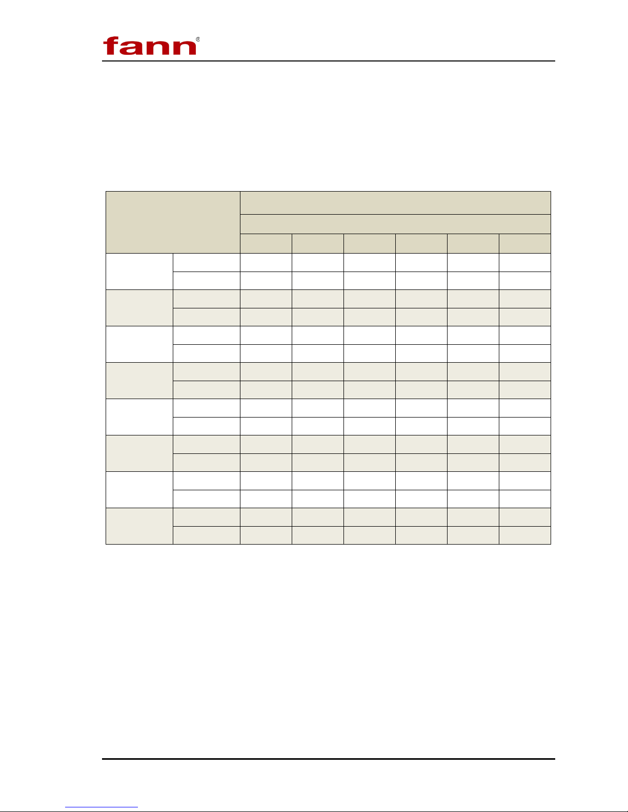
7.5 Measuring Ranges
The measuring ranges for shear stress, shear rate, and viscosity are listed in Table
7-6, 7-7 and 7-8, respectively.
Table 7-6 Shear Stress Measuring Range for Fann Direct Indicating Viscometer
Torsion Spring/
Viscometer Reading
o
F 0.2
F 0.5
F1
F2
F3
F4
F5
θ = 1
θ = 300o
θ = 1o
θ = 300o
o
θ = 1
θ = 300o
θ = 1o
θ = 300o
o
θ = 1
θ = 300o
θ = 1o
θ = 300o
o
θ = 1
θ = 300o
Shear Stress Range (dynes/cm2),
Rotor-Bob Combinations
R1 B1 R2 B1 R3 B1 R1 B2 R1 B3 R1 B4
1.02 1.02 1.02 2.01 4.1 8.2
307 307 307 605 1225 2450
2.56 2.56 2.56 5.04 10.2 20.4
766 766 766 1510 3060 6140
5.11 5.11 5.11 10.1 20.4 40.9
1533 1533 1533 3022 6125 12,300
10.22 10.22 10.22 20.1 40.8 81.8
3066 3066 3066 6044 12,250 24,500
15.3 15.3 15.3 30.2 61.3 123
4600 4600 4600 9067 18,400 36,800
20.4 20.4 20.4 40.3 81.7 164
6132 6132 6132 12,090 24,500 49,100
25.6 25.6 25.6 50.4 102 205
7665 7665 7665 15,100 30,600 61,400
(k1k2θ)
τ =
F10
θ = 1o
θ = 300o
208878 Revision N, February 2013 33
51.1 51.1 51.1 100.7 204 409
15,330 15,330 15,330 30,200 61,200 123,000
Page 34
Model 35 Viscometer Instruction Manual
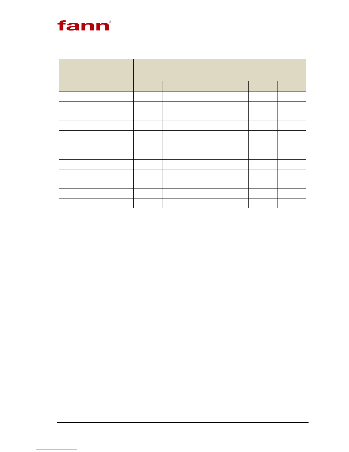
Table 7-7 Shear Rate Measuring Range for Fann Direct Indicating Viscometers
Rate of Revolution of
Outer Cylinder, N
(rpm)
0.9 1.5 4.9 0.4 0.4 0.24 0.24
1.8 3.1 9.8 0.7 0.7 0.48 0.48
3 5.1 16.3 1.1 1.1 0.8 0.8
6 10.2 32.5 2.3 2.3 1.61 1.61
30 51.1 163 11.3 11.3 8 8
60 102 325 22.6 22.6 16.1 16.1
90 153 488 33.9 33.9 24.1 24.1
100 170 542 37.7 37.7 26.8 26.8
180 306 976 67.9 67.9 48.2 48.2
200 340 1084 75.4 75.4 53.6 53.6
300 511 1627 113 113 80.4 80.4
600 1021 3254 226 226 161 161
Shear Rate Range (sec-1), γ = k3N
Rotor-Bob Combinations
R1 B1 R2 B1 R3 B1 R1 B2 R1 B3 R1 B4
208878 Revision N, February 2013 34
Page 35

Model 35 Viscometer Instruction Manual
Table 7-8 Viscosity Range in Centipoise for Fann Direct Indicating Viscometers
1)
Viscosity (cP)
(
Fann Model
Rotor-Bob Combinations
R1 B1 R2 B1 R3 B1 R1 B2 R1 B3 R1 B4
All Models, 600 rpm max
Minimum Viscosity
(
2)
(3)
0.5
0.5
(3)
2.3 4.5 12.7 25
Model 35A & 35SA
3 rpm min
Maximum Viscosity
(4)
30,000 9,400 135,000 270,000 762,000 1,500,000
Model 35A/SR 12 &
35SA/SR 12
0.9 rpm min
Maximum Viscosity
Notes:
(1) Computed for standard Torsion Spring (F1). For other torsion springs multiply viscosity range by f factor.
(2) Minimum viscosity is computed for minimum shear stress and maximum shear rate.
(3) For practical purposes the minimum viscosity is limited to 0.5 cP because of Taylor Vortices.
(4) Maximum viscosity is co mputed for maximum shear stress and minimum shear rate.
(4)
100,000 31,400 400,000 890,000 2,550,000 5,000,000
208878 Revision N, February 2013 35
Page 36

Model 35 Viscometer Instruction Manual
8 Troubleshooting and Maintenance
Troubleshooting and regular maintenance procedures are described in this section.
If more extensive maintenance or service of the instrument is required, please
contact your Fann representative.
8.1 Troubleshooting
Table 8-1 Troubleshooting Guide
Problem or Symptom Possible Cause Corrective Action
Erratic dial motion
Out of calibration
Excessive noise
Contaminated bob shaft
bearings.
Bent bob shaft.
Rotor out of alignment.
Contaminated bob shaft
bearings.
Bent bob shaft.
Bent rotor.
Damaged or incorrectly
installed torsion spring.
Incorrect motor speed.
Lubrication failure or
contamination in gears.
Worn center thrust washer. Contact Fann for repair.
Replace the bob shaft bearings
(P/N 207450).
Bend shaft slightly to
straighten it. Contact Fann for
repair or replacement.
Replace the rotor if it is
damaged. See list of rotors in
Table 9-1.
Replace the bob shaft bearings
(P/N 207450).
Bend shaft slightly to
straighten it. Contact Fann for
repair or replacement.
Replace the rotor.
See Table 9-1.
See Section 5.4 to replace the
torsion spring.
Replace the motor
(P/N 207446 or 207447).
Contact Fann for repair.
Excessive run-out of rotor
208878 Revision N, February 2013 36
Top cover not set properly. Adjust the top cover.
Damaged rotor.
Contamination in main shaft
recess.
Replace the rotor.
See Table 9-1.
Contact Fann for repair.
Page 37

Model 35 Viscometer Instruction Manual
8.2 Maintenance
The instrument should be serviced by qualified personnel only. If factory service is
required, contact Fann for return authorization.
These tips are recommended for properly caring for the viscometer.
• Clean the bob and rotor after each test.
• Periodically examine the bob and rotor for dents, abrasion, or other damage.
• Always remove the bob from the bob shaft when transporting instrument to
avoid bending bob shaft.
• Periodically test the bob shaft bearings. Operate the instrument at 3 rpm or
6 rpm without sample. Observe movement of the dial. It should not move
more than +/- 1 division.
• Rough bob shaft bearings should be replaced.
• Oiling or greasing of the viscometer is not required in normal service.
208878 Revision N, February 2013 37
Page 38

Model 35 Viscometer Instruction Manual
Part No.
F
Constant
Max Shear Stress
Color Code
207656
F0.2
77.2
307
Green
207657
F0.5
193
766
Yellow
207465
F1
386
1,533
Blue
207658
F2
772
3,066
Red
207659
F3
1,158
4,600
Purple
207660
F4
1,544
6,132
White
207661
F5
1,930
7,665
Black
207662
F10
3,860
15,330
Orange
Rotors
207523
R1, 303 Stainless Steel
207942
R2, 303 Stainless Steel
207943
R3, 303 Stainless Steel
208983
R1, Closed-end, Stainles s Stee l
208985
R2, Closed-end, Stainless Stee l
Bobs
207521
B1, 303 Stainless Steel, Hollow
207520
B2, 303 Stainless Steel, Solid
207519
B3, 303 Stainless Steel, Solid
207518
B4, 303 Stainless Steel, Solid
Sample Cups
101558383
Thermocup, 115 Volts, 50/60 Hz, 2 amps, 200oF
101558384
Thermocup, 230 Volts, 50/60 Hz, 1 amp, 200oF
207958
Double-Wall Circulating Cup
207560
Stainless Steel Sample Cup
Circulators
208754
Heat-only Circulator, 90°F to 212°F, 4 liters, 115 Volts, 60 Hz, 1,000 Watt
Cooling /Heating Circulator, -20°C to 150°C, 6 lit er s , 115 Volts, 60 Hz,
Heater Capacity 1,100 Watt
Calibration
207853
DW3 Dead Weight Calibration Kit
207124
Calibration Fluid, 10 cP, 16 oz
207119
Calibration Fluid, 20 cP, 16 oz
207120
Calibration Fluid, 50 cP, 16 oz
207121
Calibration Fluid, 100 cP, 16 oz
207122
Calibration Fluid, 200 cP, 16 oz
207123
Calibration Fluid, 500 cP, 16 oz
207125
Calibration Fluid, 30,000 cP, 16 oz
207126
Calibration Fluid, 100,000 cP, 16 oz
9 Accessories
Table 9-1 Accessories
Torsion Springs
208755
208878 Revision N, February 2013 38
Page 39

Model 35 Viscometer Instruction Manual
10 Par ts List
The Model 35 series of viscometers are listed in Table 10-1. The parts list for the
Fann Model 35 viscometers are combined in Table 10-2.
See Figure 10-1, the upper half of the Model 35 for identification numbers 1-24 and
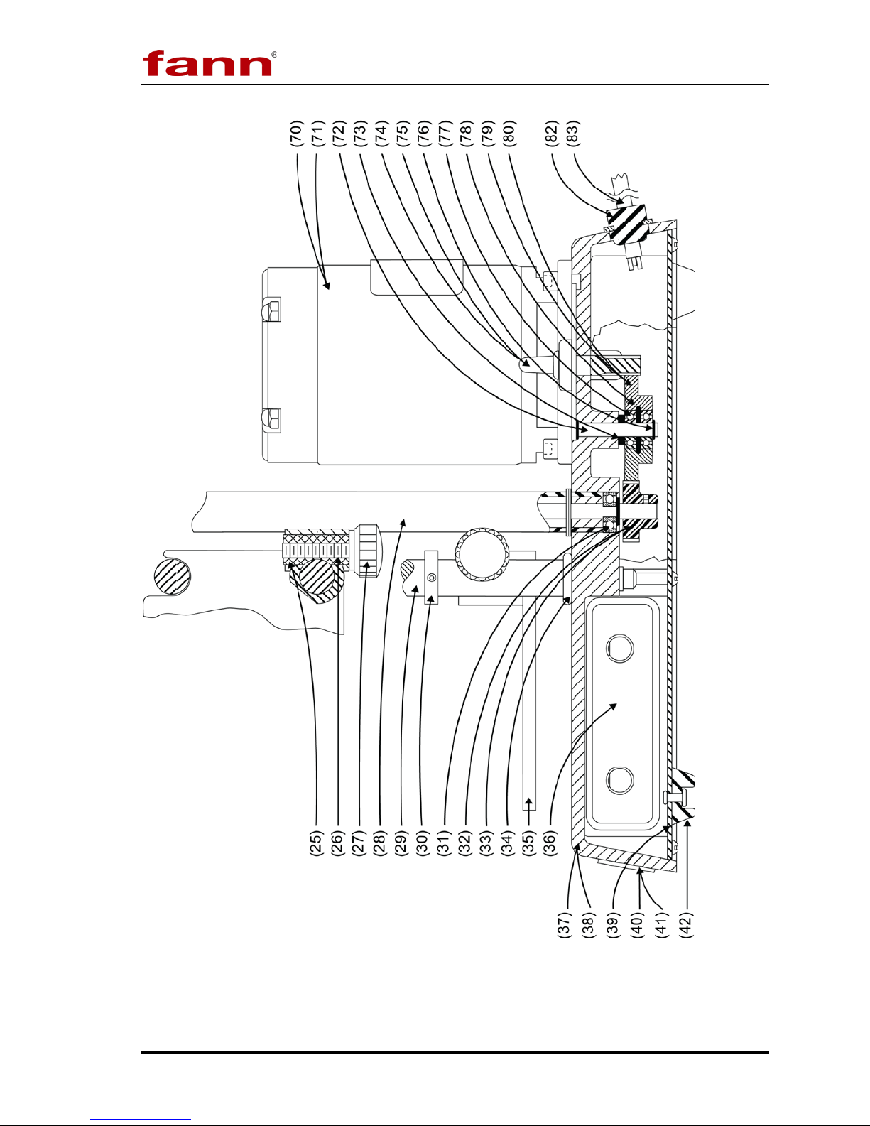
43-69 in the parts list. See Figure 10-2, the lower half of the Model 35 for
identification numbers.
Table 10-1 Model 35 Series Viscometers
Model No. Part No. Electrical
35A 207198
35SA 207199
35A/SR-12 207200
35SA/SR-12
207201
115V, 60 Hz, 90W
115V, 50 Hz, 90W
115V, 60 Hz, 90W
115V, 50 Hz, 90W
208878 Revision N, February 2013 39
Page 40

Model 35 Viscometer Instruction Manual
208878 Revision N, February 2013 40
Figure 10-1 Model 35A and 35SA - Upper
Page 41
Model 35 Viscometer Instruction Manual
208878 Revision N, February 2013 41
Figure 10-2 Model 35A and 35SA – Lower
Page 42

Model 35 Viscometer Instruction Manual
ID
Part No.
Description
1
207594
Zeroing Sleeve
2
207585
Dust Cap
3
207595
Clamp Sleeve (2)
4
207465
Torsion Spring Assembly F1
5
207557
Spring Bushing
6
207586
Lens
7
207496
Housing Cover Assembly
8
207527
Needle Pointer
9
207603
Plug Screw
10
207899
Gear Housing
11
207445
Bob Shaft & Dial Assembly
12
207144
Retainer
13
207998
Shim
14
207553
Main Shaft Gear
15
207506
Main Shaft Key
16
207867
Internal Retaining Ring (2)
17
207965
Main Shaft
18
207449
Main Shaft Bearing (2)
19
207450
Bob Shaft Bearing (2)
20
207546
Bearing Shield
21
205697
External Retaining Ring
22
207539
Splash Guard
23
207523
Rotor R-1
24
207521
Bob B-1
25
207597
Clamp Nut
26
207598
Clamp Spacer
27
207588
Clamp Screw
28
207153
Drive Shaft Tube
29
207599
Support Rod (2)
30
207593
Stop Collar
31
207437
Bearing
32
207564
Drive Shaft Gear (35A)
33
207563
Drive Shaft Gear (35SA)
34
205654
O-Ring
35
207448
Stage
36
219548
Capacitor. 7.5 µF
37
207458
Base (Model 35A, 60 Hz)
38
207204
Base (Model 35SA, 50Hz)
39
207459
Cover Plate
40
207500
Name Plate (35A)
41
207499
Name Plate (35SA)
42
205779
Rubber Feet (4)
43
207511
Shift Rod Assembly
44
207596
Detent Spring
45
207592
Gel Knob
Table 10-2 Model 35 Series Viscometer Parts Li st
208878 Revision N, February 2013 42
Page 43

Model 35 Viscometer Instruction Manual
ID
Part No.
Description
46
207452
Bushing
47
207776
Balls (6)
48
207815
Washer
49
207547
Upper Change Gear
50
207963
Worm Gear
51
207550
Lower Change Gear
52
207971
Temperature Warning Tag
53
207555
Bearing (Cover Housing)
54
207498
Speed Selection Tag
55
207559
Cluster Gear
56
207440
Jack Shaft Assembly
56a
207439
Gear Worm
56b
207438
Washer
56c
207436
Bushing
56d
207435
Jackshaft Frame
56e
207507
Shaft and Gear for Jackshaft Assembly
56f
207437
Bearing
56g
207814
External Retainer
57
207428
Spacer
58
207437
Bearing
59
207143
Internal Retaining Rings
60
207567
Clutch Spring
61
207545
Upper Drive Shaft
62
208002
Thrust Washer
63
207778
Shim
64
207817
Flat Washer
65
207152
Flex Coupling
66
207452
Bushing
67
207558
Lower Drive Shaft
68
207487
Stop Screw
69
207514
Center Shaft Gear Assembly
70
207446
Motor (35A)
71
207447
Motor (35SA)
72
207587
Idler Shaft
73
207485
Flat Washer
74
208365
Switch
75
207784
Switch Boot
76
207814
External Retainer
77
207437
Bearing (2)
78
207143
Internal Retaining Ring
79
208003
Idler Gear (35A)
80
208004
Idler Gear (35SA)
82
204371
Strain Relief
83
203512
Power Cord
208878 Revision N, February 2013 43
Page 44

Model 35 Viscometer Instruction Manual
11 Warranty and Returns
11.1 Warranty
Fann Instrument Company warrants its products to be free from defects in material
and workmanship for a period of 12 months from the time of shipment. If repair or
adjustment is necessary, and has not been the result of abuse or misuse within the
twelve-month period, please return, freight prepaid, and correction of the defect
will be made without charge.
Out of warranty products will be repaired for a nominal charge.
Please refer to the accompanying warranty statement enclosed with the product.
11.2 Returns
For your protection, items being returned must be carefully packed to prevent
damage in shipment and insured against possible damage or loss. Fann will not be
responsible for damage resulting from careless or insufficient packing.
Before returning items for any reason, authorization must be obtained from Fann
Instrument Company. When applying for authorization, please include information
regarding the reason the items are to be returned.
Our correspondence address is:
Fann Instrument Company
P.O. Box 4350
Houston, Texas USA 77210
Telephone: 281-871-4482
Toll Free: 800-347-0450
FAX: 281-871-4446
15112 Morales Road
Gate 11, Houston, Texas USA 77032
208878 Revision N, February 2013 44
 Loading...