

Fanimation ZONIX MA4660SSBNW, Showroom Series, XENO FP6728BBN User Manual
Español p. 25
MODEL #MA4660**
MODEL #MA4660SSBNW
Questions, problems, missing parts? Before returning to your retailer, call our customer
service department at 1-888-567-2055, 8 a.m.-5 p.m., EST, Monday-Friday.
ATTACH YOUR RECEIPT HERE AND REGISTER YOUR FAN AT FANIMATION.COM
READ AND SAVE THESE INSTRUCTIONS
Serial Number
Purchase Date
MA4660** Net Weight 12.46 lbs (5.65 kg)
MA4660SSBNW Net Weight 13.45 lbs (6.10 kg)
™
ZONIX WET CUSTOM CEILING FAN
6. Use only with light kits marked suitable for use in wet locations.
1. LIMITED LIFETIME MOTOR WARRANTY - If any part of your fan motor fails, due to a defect in materials or workmanship during
the lifetime of the original purchaser, Fanimation will provide the replacement part free of charge, when the defective fan is returned
to our national service center. Proof of purchase is required. Customer shall be responsible for all costs incurred in the removal or
reinstallation and shipping of the product for repairs or replacement.
2. ONE YEAR MOTOR LABOR WARRANTY - If your fan motor fails at any time within one year from the original purchase, due to
defects in materials or workmanship, labor to repair the motor will be provided free of charge at our national service center. Purchaser
will be responsible for labor charges after this one-year period. Customer shall be responsible for all costs incurred in the removal or
reinstallation and shipping of the product for repairs or replacement.
3. If any other part of your fan fails at any time within one year after original purchase, due to a defect in materials or workmanship, we
will repair, or replace, at our option, the defective part free of charge for parts and labor performed at our national service center.
4. Because of varying climate conditions, this warranty does not cover changes in the finish, including rusting, pitting, corroding,
tarnishing, or peeling.
LIMITED LIFETIME WARRANTY
Extends to the original purchaser of a Fanimation Fan
Important Safety Instructions
WARNING: To avoid fire, shock and serious personal injury, follow these instructions.
1. Read your owner’s manual and safety information before installing your new fan. Review the accompanying assembly diagrams.
2. Before servicing or cleaning unit, switch power off at service panel and lock service panel disconnecting means to prevent power
from being switched on accidentally. When the service disconnecting means cannot be locked, securely fasten a warning device, such
as a tag, to the service panel.
3. Be careful of the fan and blades when cleaning, painting, or working near the fan. Always turn off the power to the ceiling fan before
servicing.
4. Do not insert anything into the fan blades while the fan is operating.
5. Do not operate reversing switch until fan blades have come to a complete stop.
Additional Safety Instructions
1. To avoid possible shock, be sure electricity is turned off at the fuse box before wiring, and do not operate fan without blades.
2. All wiring and installation procedures must satisfy National Electrical Codes (ANSI/ NFPA 70) and Local Codes. The ceiling fan
must be grounded as a precaution against possible electrical shock. Electrical installation should be made or approved by a licensed
electrician.
3. The fan base must be securely mounted and capable of reliably supporting at least 35 lbs. See page 5 of owner’s manual for
support requirements. Consult a qualified electrician if in doubt.
4. The fan must be mounted with the fan blades at least 7 feet from the floor to prevent accidental contact with the fan blades.
5. Follow the recommended instructions for the proper method of wiring your ceiling fan. If you do not have adequate electrical
knowledge or experience, have your fan installed by licensed electrician.
6. Do not suitable for use with solid-state speed controls.
8. For supply connections, if the conductor of a fan is identified as a grounded conductor, then it should be connected to a grounded
conductor power supply. If the conductor of a fan is identified as an ungrounded conductor, then it should be connected to an ungrounded
conductor power supply. If the conductor of a fan is identified for equipment grounding, then it should be connected to an
equipment grounding conductor.
7. This fan is to be used in wet locations.
This device complies with Part 15 of the FCC Rules. Operation is subject to the following two conditions:
(1) This device may not cause harmful interference, and (2) this device must accept any interference received, including
interference that may cause undesired operation. Please note that changes or modifications not expressly approved by the
party responsible for compliance could void the user's authority to operate the equipment.
Note: This equipment has been tested and found to comply with the limits for Class B digital device, pursuant to part 15 of the
FCC Rules. These limits are designed to provide reasonable protection against harmful interference in a residential installation.
This equipment generates, uses and can radiate radio frequency energy and, if not installed and used in accordance with the
instructions, may cause harmful interference to radio or television reception, which can be determined by turning the
equipment off and on, the user is encouraged to try to correct the interference by one or more of the following measures:
- Reorient or relocate the receiving antenna.
- Increase the separation between the equipment and the receiver.
- Connect the equipment into an outlet on a circuit different from that to which the receiver is connected.
Consult the dealer or an experienced radio/TV technician for help.
WARNING: TO REDUCE THE RISK OF SHOCK, THIS FAN MUST BE INSTALLED WITH A GENERAL USE ISOLATING WALL
CONTROL/SWITCH.
WARNING: This product is designed to use only those parts supplied with this product and/or accessories designated specifically for
use with this product. Using parts and/or accessories not designated for use with this product could result in personal injury or property
damage.
WARNING:
WARNING: Do not operate this fan with a variable (Rheostat) wall controller or dimmer switch. Doing so could result in damage to the
To reduce the risk of personal injury, do not bend the blade bracket (flange or blade holder) when installing the brackets,
balancing the blades, or cleaning the fan. Do not insert foreign objects in between rotating fan blades.
ceiling fan's remote control unit.
5. This warranty is void and does not apply to damage from improper installation, neglect, accident, misuse, exposure to extremes of
heat or humidity, or as a result of any modification to the original product.
6. All costs of removal and reinstallation of the fan are the sole responsibility of the owner of the fan and not the store that sold the fan
or Fanimation.
7. Fanimation reserves the right to modify or discontinue any product at any time and may substitute any part under this warranty.
8. Under no circumstances may a fan be returned without prior authorization from Fanimation. The receipt of purchase must accompany authorized returns and must be sent freight prepaid to Fanimation. The fan to be returned must be properly packed to avoid
damage in transit; Fanimation will not be responsible for any damage resulting from improper packaging.
9. It is understood that any repair or replacement is the exclusive remedy available from Fanimation. There is no other expressed or
implied warranty. Fanimation hereby disclaims any and all implied warranties, including, but not limited to those of merchantability and
fitness for a particular purpose to the extent permitted by law. Some states do not allow limitations on implied warranties. Fanimation
will not be liable for incidental, consequential, or special damages arising out of or in conjunction with product use or performance,
except as may otherwise be accorded by law. This warranty gives you special legal rights and you may also have other rights that vary
from state to state.
10. A certain amount of wobble is normal and should not be considered a problem or a defect.
LIMITED LIFETIME WARRANTY
Extends to the original purchaser of a Fanimation Fan
Table of Contents
4. . . . . . . . . . . . . . . . . . . . . . . . . . . . . . . . . . . . . . . snoitcurtsnI gnikcapnU
Energy Effi cient Use of Ceiling Fans . . . . . . . . . . . . . . . . . . . . . . . . . . . . 5
Electrical and Structural Requirements . . . . . . . . . . . . . . . . . . . . . . . . . . 5
How to Assemble Your Ceiling Fan . . . . . . . . . . . . . . . . . . . . . . . . . . . . .7
How to Hang Your Ceiling Fan . . . . . . . . . . . . . . . . . . . . . . . . . . . . . . . . .9
How to Wire Your Ceiling Fan . . . . . . . . . . . . . . . . . . . . . . . . . . . . . . . . .
How to Install Your Canopy Housing . . . . . . . . . . . . . . . . . . . . . . . . . . .
10
11
How to Assemble the Ceiling Fan Blades . . . . . . . . . . . . . . . . . . . . . . .
How to Mounting Your Switch Cup Cover Assembly (for MA4660). . .
How to Mounting Your Switch Cup Cover Assembly
(for MA4660SSBNW). . . . . . . . . . . . . . . . . . . . . . . . . . . . . . . . . . . . . . . . .
12
11
13
MA4660 & MA4660SSBNW Parts List. . . . . . . . . . . . . . . . . . . . . . . . . . . .18
How to Clean Your Ceiling Fan Blades . . . . . . . . . . . . . . . . . . . . . . . . .
17
Maintenance . . . . . . . . . . . . . . . . . . . . . . . . . . . . . . . . . . . . . . . . . . . . . . . 17
How to Install Your Remote Control . . . . . . . . . . . . . . . . . . . . . . . . . . . . 17
MA4660 Exploded-View Illustration. . . . . . . . . . . . . . . . . . . . . . . . . . . . . 19
MA4660SSBNW Exploded-View Illustration. . . . . . . . . . . . . . . . . . . . . .
Trouble Shooting . . . . . . . . . . . . . . . . . . . . . . . . . . . . . . . . . . . . . . . . . . . 22
21
Optional Light Kit . . . . . . . . . . . . . . . . . . . . . . . . . . . . . . . . . . . . . . . . . . .
Optional Fan Blades. . . . . . . . . . . . . . . . . . . . . . . . . . . . . . . . . . . . . . . . .
21
15How to Operate Your Ceiling Fan. . . . . . . . . . . . . . . . . . . . . . . . . . . . . . .
20
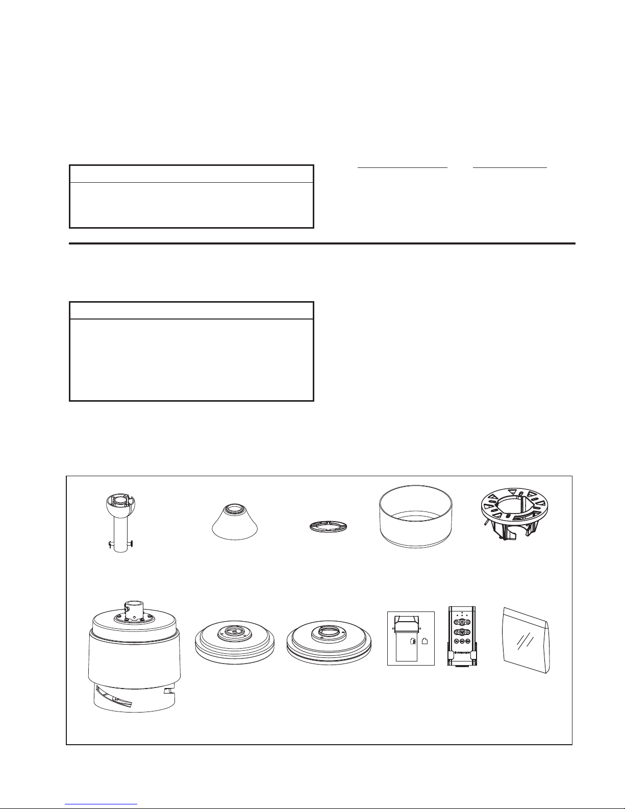
• Motor Assembly
• Downrod/Hanger Ball
Assembly
• Hanger Bracket
• Ceiling Canopy
• Canopy Screw Cover
• Motor Coupling Cover
• Switch Cup Cover Assembly
• Receiver Unit
• Hand-Held Remote
• Hardware bags:
– Ten 3/16˝-24 (blade to motor hub)
Serrated head screws & stainless
flat washers
– Four wire connectors
– Blade Balance Kit
– Two #8-32 junction box screws,
stainless steel
– Two Flat Washer, stainless steel
Unpacking Instructions
For your convenience, check-off each step. As each step is completed, place a check mark. This will ensure that all
steps have been completed and will be helpful in fi nding your place should you be interrupted.
Wiring outlet box and box connectors must be of type
required by local code. The minimum wire would be a 3conductor (2-wire with ground) of the following size:
NOTE: Place the parts from the loose parts bags in a small
container to keep them from being lost. If any parts are missing,
contact your local retailer.
Tools Needed for Assembly Materials
Wire Size A.W.G.Installed Wire Length
14
12
Up to 50 ft.
50 - 100 ft.
NOTE: If you are uncertain of part description, refer to
exploded view illustration.
4
1. Check to see that you have received the following
parts:
Switch Cup Cover
Assembly
(MA4660**)
Switch Cup Cover
Assembly
(MA4660SSBNW)
Hardware Bags
Motor Assembly
Downrod/
Hanger Ball
Assembly
Hanger Bracket
• One Phillips head screwdriver
• One stepladder
• One ¼˝ blade screwdriver
• One wire stripper
• One hex wrench
Ceiling Canopy
Motor Coupling Cover
▲
WARNING
Do not install or use fan if any part is damaged or
missing. This product is designed to use only those
parts supplied with this product and/or any accessories
designated specifically for use with this product by
Fanimation. Substitution of parts or accessories not
designated for use with this product by Fanimation could
result in personal injury or property damage. Contact
your retail store for missing or damaged parts.
▲
WARNING
Before assembling your ceiling fan, refer to section on
proper method of wiring your fan (page 10). If you feel you
do not have enough wiring knowledge or experience,
have your fan installed by a licensed electrician.
Canopy
Screw Cover
This manual is designed to make it as easy as possible for you
to assemble, install, operate, and maintain your ceiling fan
Hand-Held
Remote
Receiver Unit
– Bag Assembly Safety Cable

5
Energy Efficient Use of Ceiling Fans
Ceiling fan performance and energy savings rely
heavily on the proper installation and use of the ceiling
fan. Here are a few tips to ensure efficient product
performance.
Using the Ceiling Fan Year Round
Summer Season: Use the ceiling fan in the counter-
clockwise direction. The airflow produced by the ceiling
fan creates a wind-chill effect, making you “feel” cooler.
Select a fan speed that provides a comfortable breeze,
lower speeds consume less energy.
Winter Season: Reverse the motor and operate the ceiling
fan at low speed in the clockwise direction. This produces
a gentle updraft, which forces warm air near the ceiling
down into the occupied space.Remember to adjust your
thermostat when using your ceiling fan - additional energy
and dollar savings could be realized with this simple step!
Electrical and Structural Requirements
Your new ceiling fan will require a grounded electrical
supply line of 120 volts AC, 60 HZ, 15 Amp Circuit.
Electrical code requires use of a fan-rated outlet box to
support the extra weight and motion associated with a
ceiling fan. A fan-rated box will be labeled as such and
typically supports up to a 70lbs ceiling fan. Fan-Rated
Outlet Boxes vary in ratings and design. Ensure the
ratings of your ceiling fan outlet box meet the
requirements for the ceiling fan being installed. Figure 1,
Figure 2 and Figure 3 depicts different structural
configurations that may be used for mounting the
outlet box.
Low-profile use (Figure 1)
A 1
2-in.-deep pancake box is meant to be screwed to a
joist or block. It’s used if only one cable is coming into
the box. It is also available in a saddle-mount
configuration.
CEILING
2" x 4"
CEILING JOIST
OUTLET BOX
Figure 1
Figure 2
2" x 4"
CEILING JOIST
CEILING
OUTLET BOX
Deep-profile use (Figure 2)
A 2-1
-in.-deep box can be attached to blocking
between joists and is roomy enough to handle more
than one cable.
Choosing the Appropriate Mounting Location
Ceiling fans should be installed, or mounted, in the middle
of the room and at least 7 feet from floor to the blade and
18 inches from wall to the blade. If ceiling height allows,
install the fan 8 - 9 feet from floor to the blade for optimal
airflow. Consult your Fanimation Retailer for optional
mounting accessories.
Turn Off When Not in the Room
Ceiling fans cool people, not rooms. If the room is
unoccupied, turn off the ceiling fan to save energy.
6
Electrical and Structural Requirements (Continued)
If your fan is to replace an existing light fixture, turn
electricity off at the main fuse box at this time and
remove the existing light fixture.
Turning off wall switch is not sufficient. To avoi d
possible electrical shock, be sure electricity is
turned off at the main fuse box before wiring. All
wiring must be in accordance with National and
Local codes and the ceiling fan must be properl y
grounded as a precaution against possible electrical
shock.
WARNING
To reduce the risk of fire, electrical shock, or
personal injury, mount fan to outlet box marked
acceptable for fan support of 15.88 kg (35 lbs) or less.
Use screws supplied with outlet box. Most outlet
boxes commonly used for support of light fixtures
are not acceptable for fan support and may need to
be replaced. Consult a qualified electrician if
in doubt.
WARNING
Brace use (Figure 3)
Paired with a deep box, this hanger is meant to span
between two joists and takes the place of wooden
blocking.
To avoid fire or shock, follow all wiring instructions
carefully. Any electrical work not described in these
instructions should be done or approved by a
licensed electrician.
WARNING
Figure 3
CEILING JOIST
CEILING
OUTLET BOX
Do not operate this fan with a variable (Rheostat) wall
controller or dimmer switch. Doing so could result in
damage to the ceiling fan's remote control unit.
WARNING
Downrod
Set Screw
Hanger Ball
7
How to Assemble Your Ceiling Fan
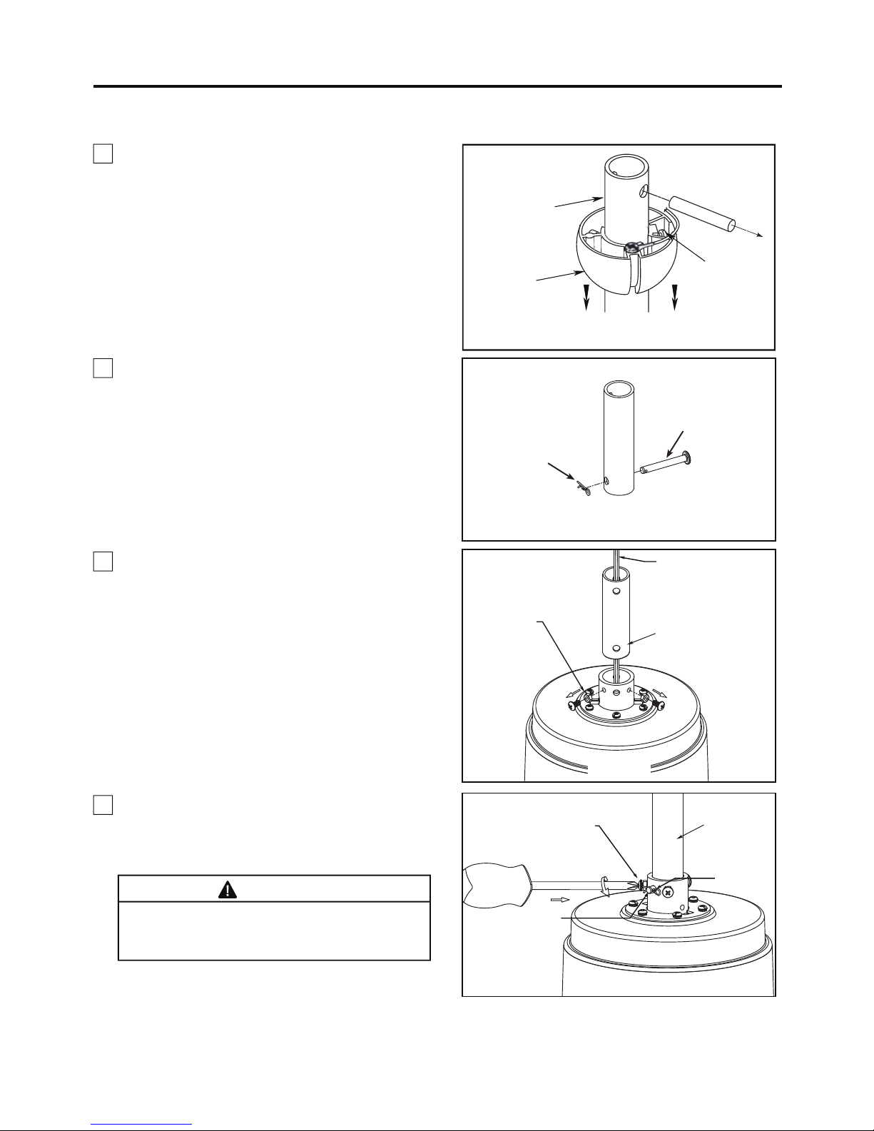
1. Remove the hanger ball portion from the downrod/
hanger ball assembly by loosening the set screw in the
hanger ball until the ball falls freely down the downrod.
Remove the pin from the downrod, then remove the
hanger ball. Retain the pin and hanger ball for reinstal-
lation in Step 6. (Figure 1)
Downrod
Figure 1
Figure 2
4. Insert downrod into the downrod support on top of
the motor. Install the clevis pin by aligning the holes
in the downrod support with holes in the downrod.
Secure clevis pin with hairpin clip. Tighten the two set
screws with nuts in the downrod support. (Figure 4)
WARNING
It is critical that the clevis pin in the downrod support
is properly installed and the set screws and nuts are
securely tightened. Failure to do so could result in
the fan falling.
2. Remove the hairpin clip and clevis pin from the
bottom of the downrod. Retain the pin and clip for
reinstallation in Step 4. (Figure 2)
Figure 3
Black, White, Blue Wires
and Safety Cable
Set Screws
and Nuts (2)
3. Loosen the two set screws and locking nuts in
the downrod support of the motor assembly. Route
the black, white and blue wires and safety cable
through the downrod. (Figure 3)
Hairpin Clip
Clevis Pin
Downrod
Set Screws and
Locking Nuts (2)
Clevis Pin
Figure 4
Hairpin Clip
8
How to Assemble Your Ceiling Fan (continued)
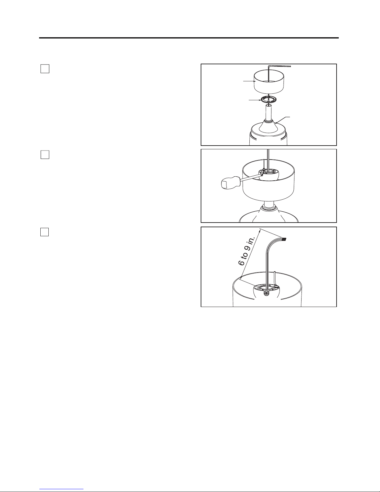
7. Cut off excess lead wire approximately 6 to 9 inches
above top of the downrod. Strip insulation off 1/2 inch
from the end of each lead wire. (Figure 7)
NOTE:
All set screws must be checked, and retightened
where necessary, before installation.
Figure 6
Motor Coupling
Cover
Ceiling Canopy
Canopy Screw
Cover
5. Route wires and safety cable through motor coupling
cover, canopy screw cover and ceiling canopy.
(Figure 5)
Figure 5
Figure 7
6. Reinstall the hanger ball on the downrod as follows.
Route the black, white and blue wires and safety cable
through the hanger ball. Position the pin through the
two holes in the downrod and align the hanger ball
so the pin is captured in the groove in the top of the
hanger ball. Pull the hanger ball up tight against the
pin. Securely tighten the set screw in the hanger
ball. A loose set screw could create fan wobble.
(Figure 6)
How to Hang Your Ceiling Fan
9
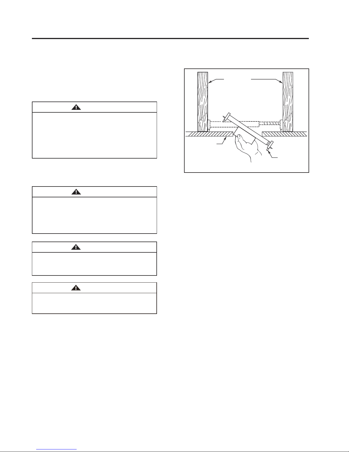
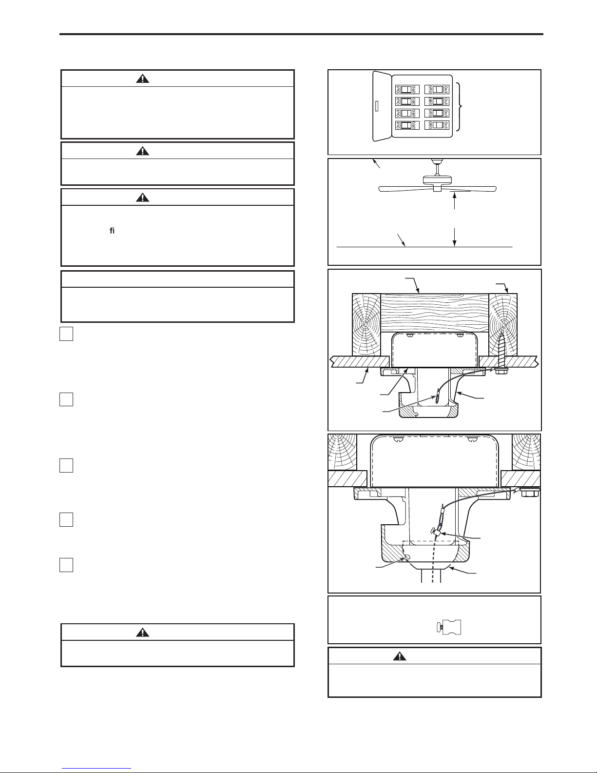
1. Using the 3⁄8˝ x 2˝ lag bolt and flat washer, attach
safety cable to ceiling joist or wood structural member.
The lag bolt will pass through the flat washer, safety
cable loop, and into the building structure (Figure 3).
You will first drill a ¼˝ pilot hole into the building structure
to prevent splitting or cracking.
2. Securely attach the hanger bracket to ceiling junction
box acceptable for ceiling fan support.
NOTE: Ceiling support cable cannot be secured to
junction box only, it must be directly secured to ceiling
joist or structural member using the ⅜˝ x 2˝ lag bolt and
fl at washer. (Figure 3)
3. Make sure the electrical supply wires, including the
hanger bracket grounding wire and safety cable are
pulled through the downrod, between the hanger bracket
and the junction box so that electrical connections can be
made later.
Carefully lift the fan and seat the downrod/hanger ball
assembly on the hanger bracket that was just attached to
the ceiling joist. Be sure the groove in the ball is lined up
with tab on the hanger bracket. (Figure 4)
5. Attach the safety cable to ceiling support cable. Slide
cable clamp onto safety cable (from fan). Place the end
of cable through the loop of ceiling support cable. Pull as
much cable through loop as possible. Feed end of cable
into clamp hole and firmly tighten screw (Figure 4). Cut
off excess safety cable.
˝ ˝ r
r.
r
˝ ˝
fl r.
r.
of
4.
WARNING
The fan must be hung with at least 7´ of clearance from
floor to blades. (Figure 2)
WARNING
The outlet box must be securely anchored and capable
of withstanding a load of at least 35 lbs. Hanger bracket
must seat
rmly against outlet box. If the outlet box is
recessed, remove wallboard until bracket contacts box.
If bracket and/or outlet box are not securely attached,
the fan could wobble or fall.
CAUTION
Do not connect fan blades until the fan is completely
installed. Hanging fan with blades connected may result
in damage to the fan blades.
WARNING
To avoid possible electrical shock, be sure electricity is
turned off at the main fuse box before hanging. (Figure 1)
NOTE: If you are not sure if the outlet box is grounded,
contact a licensed electrician for advice, as it must be
grounded for safe operation.
WARNING
Failure to seat tab in groove could cause damage to
electrical wires and possible shock or fire hazard.
Figure 2
CEILING
FLOOR
NO LESS
THAN
7 FEET
Figure 1
MAIN FUSE BOX
WOOD MEMBER
(2” X 4” APPROX.)
CEILING JOIST
CEILING
JUNCTION
BOX
HANGER BRACKET
C EI LI N G
SUPP ORT
CABLE
Figure 3
X 1
HARDWARE USED:
Figure 4
TAB
NOTE: SUPPLY WIRES AND FAN
WIRES OMITTED FOR CLARITY
DOWNROD/HANGER
BALL ASSEMBLY
ATTACH SAFETY
CABLE TO CEILING
SUPPORT CABLE
CEILING SUPPORT
CABLE CLAMP
W/SCREW
To avoid possible shock, do not pinch wires
between the downrod/hanger ball assembly and the
hanger bracket.
WARNING
How to Wire Your Ceiling Fan
Bl
Light
or
W
or
NOTE: The remote unit has 32 different code
combinations. To prevent possible interference from or to
other remote units, simply change the combination code
in the remote and receiver.
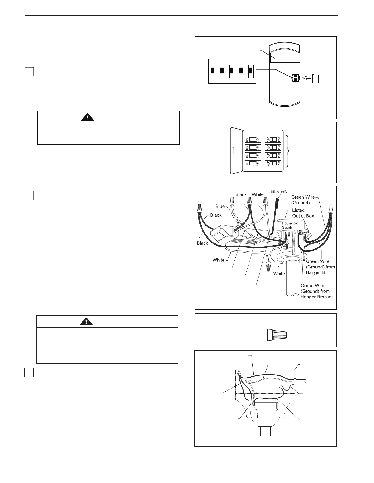
1. To set the code on receiver unit, slide dip switches to
the same positions as set on the remote. If complete the
receiver code setting process, put the rubber cover
(included) in the receiver unit. (Figure 1)
NOTE: Factory setting is all up. Do not use this position.
WARNING
To avoid possible electrical shock, be sure electricity
is turned off at the main fuse box before wiring
(Figure 2).
Receiver Unit
ON DIP
1 2 3 4 5
Dip Switch
Rubber Cover
Figure 1
NOTE:
If you are not sure if the outlet box is
grounded, contact a licensed electrician for advice, as
it must be grounded for safe operation.
CAUTION: INCORRECT WIRE CONNECTION WILL
DAMAGE THIS RECEIVER.
2. Connect green wires from hanger bracket and
downrod to bare (ground) wire using wire connector.
Connect black wire from receiver unit marked “AC IN L”
to black supply wire using wire connector. Connect white
wire from receiver unit marked “AC IN N” to white supply
wire using wire connector. Connect white wire from
receiver unit marked “TO MOTOR N” to white wire from
fan using wire connector supplied with receiver unit.
Connect black wire from receiver unit marked “TO
MOTOR L” to black wire from fan using wire connector
supplied with receiver unit. Lastly, connect blue wire
from receiver unit to the blue fan light wire using wire
connector supplied with receiver unit. (Figure 3)
NOTE:
If you feel that you do not have enough electrical
wiring knowledge or experience, have your fan installed
by a licensed electrician.
WARNING
Check to see that all connections are tight, including
ground, and that no bare wire is visible at the wire
connectors except for the ground wire. Do not
operate fan until the blades are in place. Noise and
motor damage could result.
3. After connections have been made, turn leads
upward and carefully push leads into the outlet
box, with the white and green leads to one side
of the box and the black leads to the other side.
(Figure 4)
ue to
Black to Mot
hite to Mot
Green Wire
from Supply
(Ground)
Green Wire
from Hanger
Bracket (Ground)
Figure 2
Figure 3
HARDWARE USED:
CONNECTORS
White Wire
from Supply
White Wire
from Receiver
Receiver
MAIN FUSE BOX
x 6WIRE
Listed
Outlet Box
Household
Supply
Black Wire
from Supply
all
10
Green Wire
from Hanger
Ball (Ground)
Figure 4
Black Wire
from Receiver
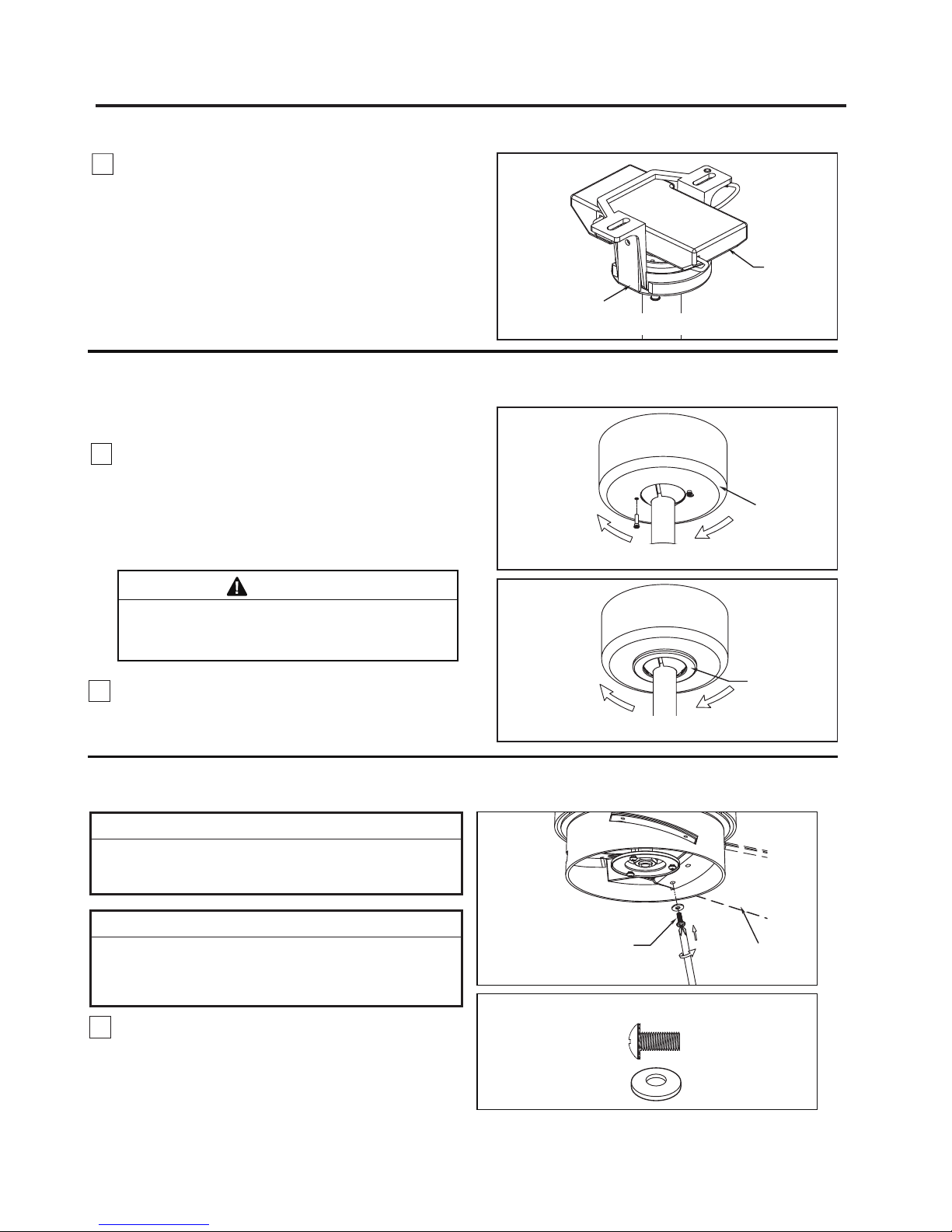
4. Once the connection has been made, slide the
receiver into the hanger bracket, taking care not to
pinch the wires. (Figure 5)
How to Wire Your Ceiling Fan (continued)
How to Install Your Canopy Housing
2. Securely attach and tighten the canopy screw cover
over the shoulder screws in the hanger bracket utilizing
the keyslot twist-lock feature. (Figure 2)
1. Remove one of the two shoulder screws in the
hanger bracket. Loosen the second shoulder screw
without fully removing it. Assemble canopy by
rotating key slot in canopy over shoulder screw in
hanger bracket. Tighten shoulder screw. Fully
assemble and tighten second shoulder screw that
was previously removed. (Figure 1)
WARNING
To avoid possible fire or shock, make sure that the
electrical wires are completely inside the canopy
housing and not pinched between the housing and the
ceiling.
NOTE: This step is applicable after the neccessary
wiring is completed.
Ceiling Canopy
11
Canopy Screw
Cover
Receiver
Hanger Bracket
Figure 5
Figure 2
How to Assemble the Ceiling Fan Blades
1. Carefully slide the blade through the slot. Securely
fasten the three blades with serrated-head screws with
flat washers. Do not over-tighten. (Figure 1)
INSTALLATION NOTE
Do not connect fan blades until the fan is completely
installed. Installing the fan with blades assembled may
result in damage to the fan blades.
▲
WARNING
To reduce the risk of personal injury, do not bend the
blades when installing, balancing or cleaning the fan.
Do not insert foreign objects in between the rotating
blades.
NOTE: You will find the fan blade set packed in its own
carton and hardware bag in the fan box.
Serrated-head
Screw with Flat
Washer (3 per blade)
Blade
(Not included)
x 9
x 9
Serrated Head
Screw
Flat Washer
HARDWARE USED:
Figure 1
Figure 1
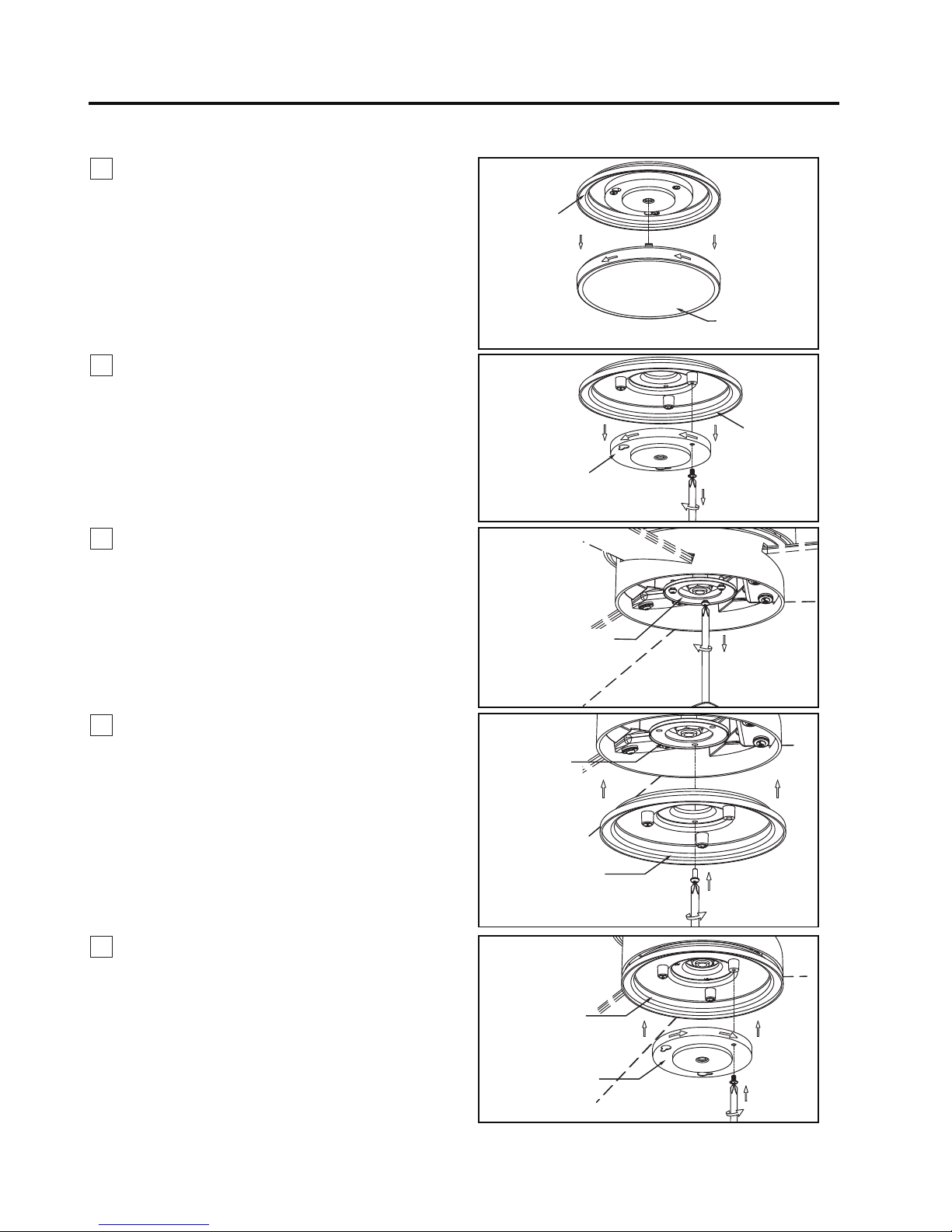
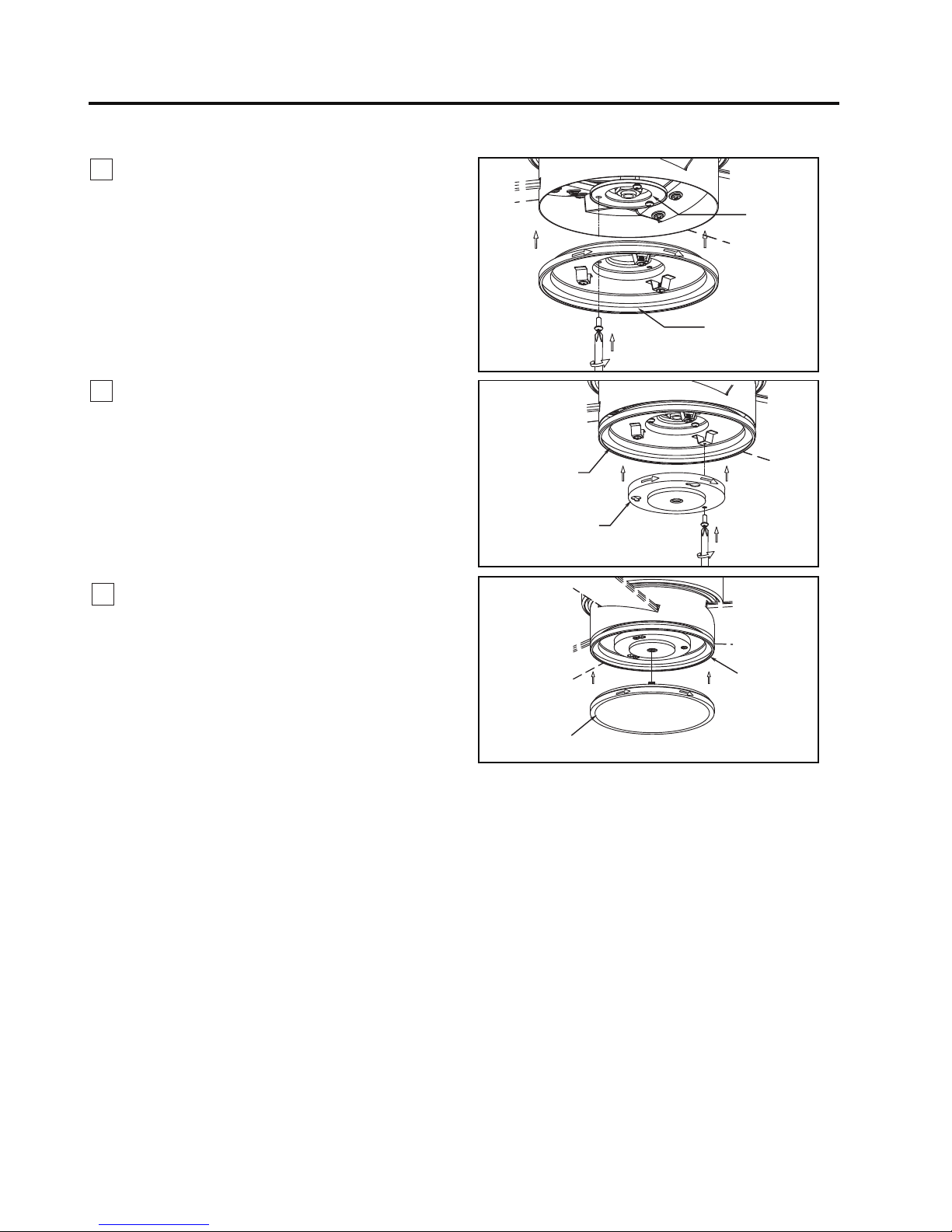
1. Remove the switch cover from the switch cup
cover assembly by twisting in a counterclockwise
direction. Retain the switch cover for Step 6.
(Figure 1)
2. Remove one of the three screws in the support-
cover switch cup and retain the screw for Step 5.
Slightly loosen the remaining two screws and remove
the inner-switch cup. Retain the inner-switch cup for
reassembly in Step 5. (Figure 2)
3. Remove the three screws in the support bracket at
the bottom of motor assembly and retain the screws
for later. (Figure 3)
4. Attach the support-cover switch cup to the support
flange using the previously removed three screws
and fully tighten. (Figure 4)
5. Assemble the inner-switch cup to the support-cover
switch cup using the two key slots in the inner-switch
cup. Replace the previously removed screw and
securely tighten all three screws. (Figure 5)
12
Motor Assembly
Figure 1
Switch Cover
Support-Cover
Switch Cup
Support-Cover
Switch Cup
Support-Cover
Switch Cup
Inner-Switch Cup
Inner-Switch Cup
Figure 2
Figure 4
Figure 5
How to Mounting Your Switch Cup Cover Assembly (for MA4660)
Figure 3
Switch Cup Cover
Assembly
Motor Assembly
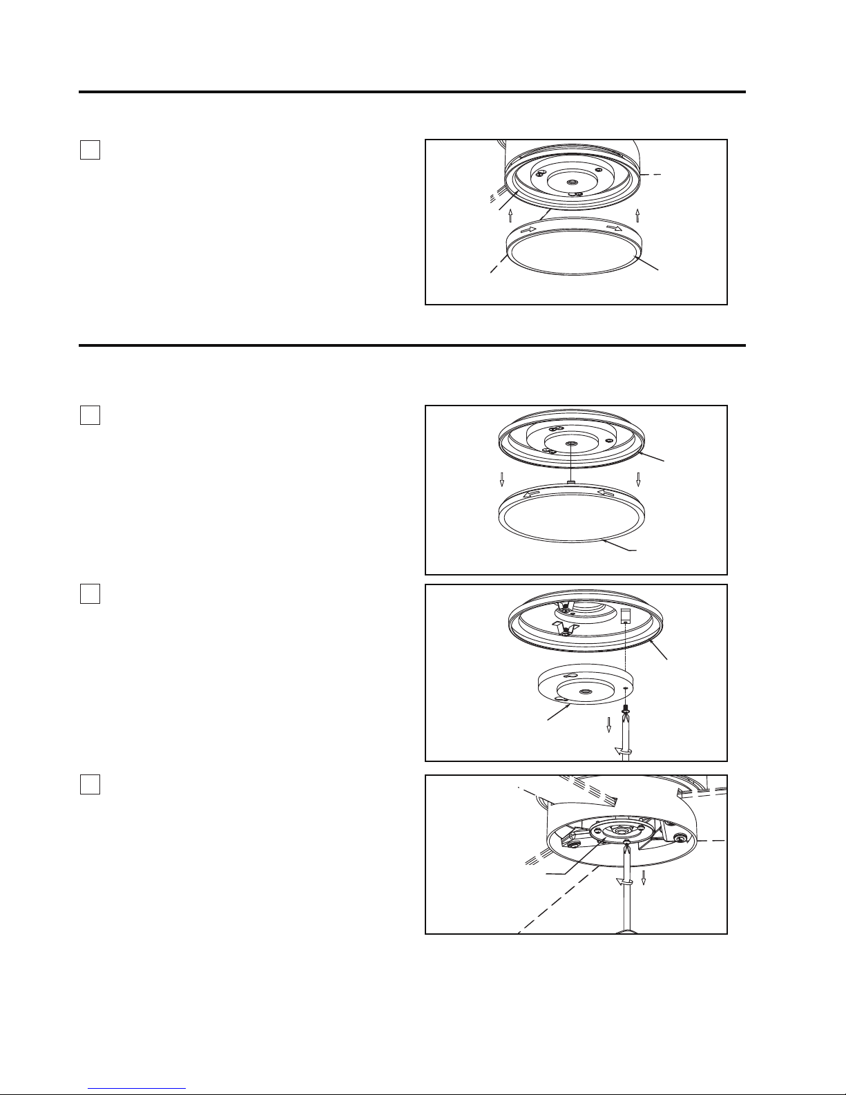
Figure 1
Inner-Switch Cup
Figure 2
Figure 3
Switch Cup
Cover Assembly
Motor Assembly
How to Mounting Your Switch Cup Cover Assembly (for MA4660SSBNW)
6. Assemble the switch cup to the support-cover
switch cup by twisting in a clockwise direction.
(Figure 6)
13
Support-Cover
Switch Cup
Figure 6
How to Mounting Your Switch Cup Cover Assembly (for MA4660) continued
Switch Cover
1. Remove the switch cover from the switch cup
cover assembly by twisting in a counterclockwise
direction. Retain the switch cover for Step 6.
(Figure 1)
2. Remove one of the three screws in the supportcover switch cup and retain the screw for Step 5.
Slightly loosen the remaining two screws and remove
the inner-switch cup. Retain the inner-switch cup for
reassembly in Step 5. (Figure 2)
Switch Cover
Support-Cover
Switch Cup
3. Remove the three screws in the support bracket at
the bottom of motor assembly and retain the screws
for later. (Figure 3)
14
Motor
Assembly
Figure 4
Figure 5
How to Mounting Your Switch Cup Cover Assembly (for MA4660SSBNW) continued
Figure 6
Support-Cover
Switch Cup
Support-Cover
Switch Cup
Inner-Switch Cup
4. Attach the support-cover switch cup to the support
flange using the previously removed three screws
and fully tighten. (Figure 4)
5. Assemble the inner-switch cup to the support-cover
switch cup using the two key slots in the inner-switch
cup. Replace the previously removed screw and
securely tighten all three screws. (Figure 5)
6. Assemble the switch cup to the support-cover
switch cup by twisting in a clockwise direction.
(Figure 6)
Support-Cover
Switch Cup
Switch Cover
How to Operate Your Ceiling Fan
Figure 2
MAIN FUSE BOX
Figure 1
For illustrative purposes only-not
intended to cover all types of controls
2. Restore electrical power to the outlet box by turning
the electricity on at the main fuse box. (Figure 2)
Check to see that all connections are tight, including
ground, and that no bare wire is visible at the wire
connectors, except for the ground wire. Do not
operate fan until the blades are in place. Noise and
fan damage could result.
WARNING
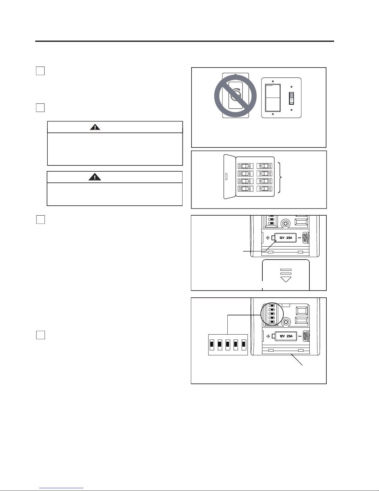
1. IMPORTANT: Using a full range dimmer switch
(not included) to control fan speed will damage the fan.
To reduce the risk of fire or electrical shock, do not use
a full range dimmer switch to control the fan speed.
(Figure 1)
WARNING
Do not operate this fan with a variable (Rheostat) wall
controller or dimmer switch. Doing so could result in
damage to the ceiling fan's remote control unit.
15
3. To make fan operational, install 23A/12V battery
(included) in hand-held remote transmitte
4. To set the remote code with a small screwdriver or
ball point pen (neither included), slide dip switches
firmly up or down. (Figure 4)
r, with fan
power off. Then follow the remote code setting
process. (If not used for long periods of time, remove
battery toprevent damage to transmitter). Store the
remote away from excessive heat or humidly.
(Figure 3)
NOTE: The remote unit has 32 different code
combinations. To prevent possible interference from
or to other remote units, simply change the
combination code in the remote and receiver.
NOTE: Factory setting is all up. Do not use this
position.
12V 23A
Battery (1 pcs)
Figure 3
Figure 4
Dip Switch
ON DIP
1 2 3 4 5
Remote
 Loading...