

Fanimation Torrento FP920 Owner's Manual
The Torrento
Pedestal Fan
®
Wet Location Model
Model No. FP920
OWNER’S MANUAL
READ AND SAVE THESE INSTRUCTIONS
Net Weight 75 lbs.

FP920 – TORRENTO
®
Important Safety Instructions
WARNING: To avoid fire, shock and serious personal injury, follow these instructions.
1. Read your owner’s manual and safety information before installing your new fan. Review the accompanying assembly diagrams.
2. Before servicing or cleaning unit, switch power off at service panel and lock service panel disconnecting means to prevent power
from being switched on accidentally. When the service disconnecting means cannot be locked, securely fasten a warning device, such
as a tag, to the service panel.
3. Be careful of the fan and blades when cleaning, painting, or working near the fan. Always turn off the power to the fan before
servicing.
4. Do not insert anything into the fan blades while the fan is operating.
5. Do not operate reversing switch until fan blades have come to a complete stop.
Additional Safety Instructions
1. To avoid possible shock, be sure electricity is turned off at the fuse box before wiring, and do not operate fan without blades.
2. All wiring and installation procedures must satisfy National Electrical Codes (ANSI/ NFPA 70-1999). Use the National
Electrical Code if Local Codes do not exist. The Pedestal fan must be grounded as a precaution against possible electrical
shock. Electrical installation should be made or approved by a licensed electrician.
3. The fan base must be securely mounted and capable of reliably supporting at least 100 lbs. Outlet boxes are not acceptable
for fan support. See page 8 of owner’s manual for support requirements.
4. CAUTION: To reduce the risk of personal injury, mount the fan base to the floor using the hardware provided with your fan.
5. The fan must be mounted with the fan blades at least 7 feet from the floor to prevent accidental contact with the fan blades.
6. Follow the recommended instructions for the proper method of wiring your Pedestal fan.
WARNING: To Reduce The Risk Of Fire, Electric Shock, And Injury To Persons, FP920 Torrento
Installed With Support Shaft And Blades That Are Marked “For Use Only With Fanimation FP920 Torrento
Indicate The Suitability With This Model. Other Support Shaft And Blades Cannot Be Substituted.
WARNING: This product is designed to use only those parts supplied with this product and/or accessories designated
specifically for use with this product. Using parts and/or accessories not designated for use with this product could result in
personal injury or property damage.*
WARNING: To reduce the risk of personal injury, do not bend the blade bracket (flange or blade holder) when installing the
brackets, balancing the blades, or cleaning the fan. Do not insert foreign objects in between rotating fan blades.
®
Pedestal Fan Must Be
®
Pedestal Fan” To
LIMITED LIFETIME WARRANTY
Extends to the original purchaser of a Fanimation Fan
1. LIMITED LIFETIME MOTOR WARRANTY - If any part of your fan motor fails, due to a defect in materials or workmanship during
the lifetime of the original purchaser, Fanimation will provide the replacement part free of charge, when the defective fan is returned
to our national service center. Proof of purchase is required. Customer shall be responsible for all costs incurred in the removal or
reinstallation and shipping of the product for repairs or replacement.
2. ONE YEAR MOTOR LABOR WARRANTY - If your fan motor fails at any time within one year from the original purchase, due to
defects in materials or workmanship, labor to repair the motor will be provided free of charge at our national service center. Purchaser
will be responsible for labor charges after this one-year period. Customer shall be responsible for all costs incurred in the removal or
reinstallation and shipping of the product for repairs or replacement.
3. If any other part of your fan fails at any time within one year after original purchase, due to a defect in materials or workmanship, we
will repair, or replace, at our option, the defective part free of charge for parts and labor performed at our national service center.
4. Because of varying climate conditions, this warranty does not cover changes in the finish, including rusting, pitting, corroding,
tarnishing, or peeling.
5. This warranty is void and does not apply to damage from improper installation, neglect, accident, misuse, exposure to extremes of
heat or humidity, or as a result of any modification to the original product.
6. All costs of removal and reinstallation of the fan are the sole responsibility of the owner of the fan and not the store that sold the fan
or Fanimation.
7. Fanimation reserves the right to modify or discontinue any product at any time and may substitute any part under this warranty.
8. Under no circumstances may a fan be returned without prior authorization from Fanimation. The receipt of purchase must
accompany authorized returns and must be sent freight prepaid to Fanimation. The fan to be returned must be properly packed to
avoid damage in transit; Fanimation will not be responsible for any damage resulting from improper packaging.
9. It is understood that any repair or replacement is the exclusive remedy available from Fanimation. There is no other expressed or
implied warranty. Fanimation hereby disclaims any and all implied warranties, including, but not limited to those of merchantability and
fitness for a particular purpose to the extent permitted by law. Some states do not allow limitations on implied warranties. Fanimation
will not be liable for incidental, consequential, or special damages arising out of or in conjunction with product use or performance,
except as may otherwise be accorded by law. This warranty gives you special legal rights and you may also have other rights that vary
from state to state.
10. A certain amount of wobble is normal and should not be considered a problem or a defect.
Table of Contents
Unpacking Instructions . . . . . . . . . . . . . . . . . . . . . . . . . . . . . . . . . . . . . . . . . . . . . . . . . . . . . . . . . . . . . . . . . . 3
Electrical Requirements . . . . . . . . . . . . . . . . . . . . . . . . . . . . . . . . . . . . . . . . . . . . . . . . . . . . . . . . . . . . . . . . . . 4
How to Assemble Your Pedestal Fan . . . . . . . . . . . . . . . . . . . . . . . . . . . . . . . . . . . . . . . . . . . . . . . . . . . . . . . 4
Mounting the Fan Blades . . . . . . . . . . . . . . . . . . . . . . . . . . . . . . . . . . . . . . . . . . . . . . . . . . . . . . . . . . . . . . . . . 7
Mounting Fan Base to Floor. . . . . . . . . . . . . . . . . . . . . . . . . . . . . . . . . . . . . . . . . . . . . . . . . . . . . . . . . . . . . . . 8
Operating Instructions - Pull Chain. . . . . . . . . . . . . . . . . . . . . . . . . . . . . . . . . . . . . . . . . . . . . . . . . . . . . . . . . 9
Maintenance . . . . . . . . . . . . . . . . . . . . . . . . . . . . . . . . . . . . . . . . . . . . . . . . . . . . . . . . . . . . . . . . . . . . . . . . . . . 9
Blade Cleaning . . . . . . . . . . . . . . . . . . . . . . . . . . . . . . . . . . . . . . . . . . . . . . . . . . . . . . . . . . . . . . . . . . . . . . . . . 9
Parts List . . . . . . . . . . . . . . . . . . . . . . . . . . . . . . . . . . . . . . . . . . . . . . . . . . . . . . . . . . . . . . . . . . . . . . . . . . . . . 10
Exploded-View Illustration . . . . . . . . . . . . . . . . . . . . . . . . . . . . . . . . . . . . . . . . . . . . . . . . . . . . . . . . . . . . . . . 11
Trouble Shooting. . . . . . . . . . . . . . . . . . . . . . . . . . . . . . . . . . . . . . . . . . . . . . . . . . . . . . . . . . . . . . . . . . . . . . . 12
FP920 – TORRENTO
®
This Manual is Designed to Make it as Easy as Possible for You
to Assemble, Install, Operate, and Maintain Your Pedestal Fan
Tools Needed for Assembly
• One Phillips head screwdriver
• One ¼˝ blade screwdriver
• One stepladder
NOTE: Place the parts from the loose parts bags in a
small container to keep them from being lost. If any parts
are missing, contact your local retailer.
CAUTION
▲
To Reduce the Risk of Personal Injury, this Product Must
be Secured as Described Below.
▲
WARNING
Before assembling your floor fan, refer to section on
proper method of wiring your fan (page 4). If you feel
you do not have enough wiring knowledge or experience,
have your fan installed by a licensed electrician.
To Reduce The Risk Of Fire Or Electric Shock, Do Not Use
This Fan With Any Solid-State Speed Control Device.
NOTE: This Product Intended For Outdoor Use ONLY.
WARNING
Unpacking Instructions
For your convenience, check-off each step. As each step is completed, place a check mark. This will ensure that all
steps have been completed and will be helpful in fi nding your place should you be interrupted.
▲
WARNING
Do not install or use fan if any part is damaged or
missing. This product is designed to use only those
parts supplied with this product and/or any accessories
designated specifically for use with this product by
Fanimation. Substitution of parts or accessories not
designated for use with this product by Fanimation could
result in personal injury or property damage. Contact
your retail store for missing or damaged parts.
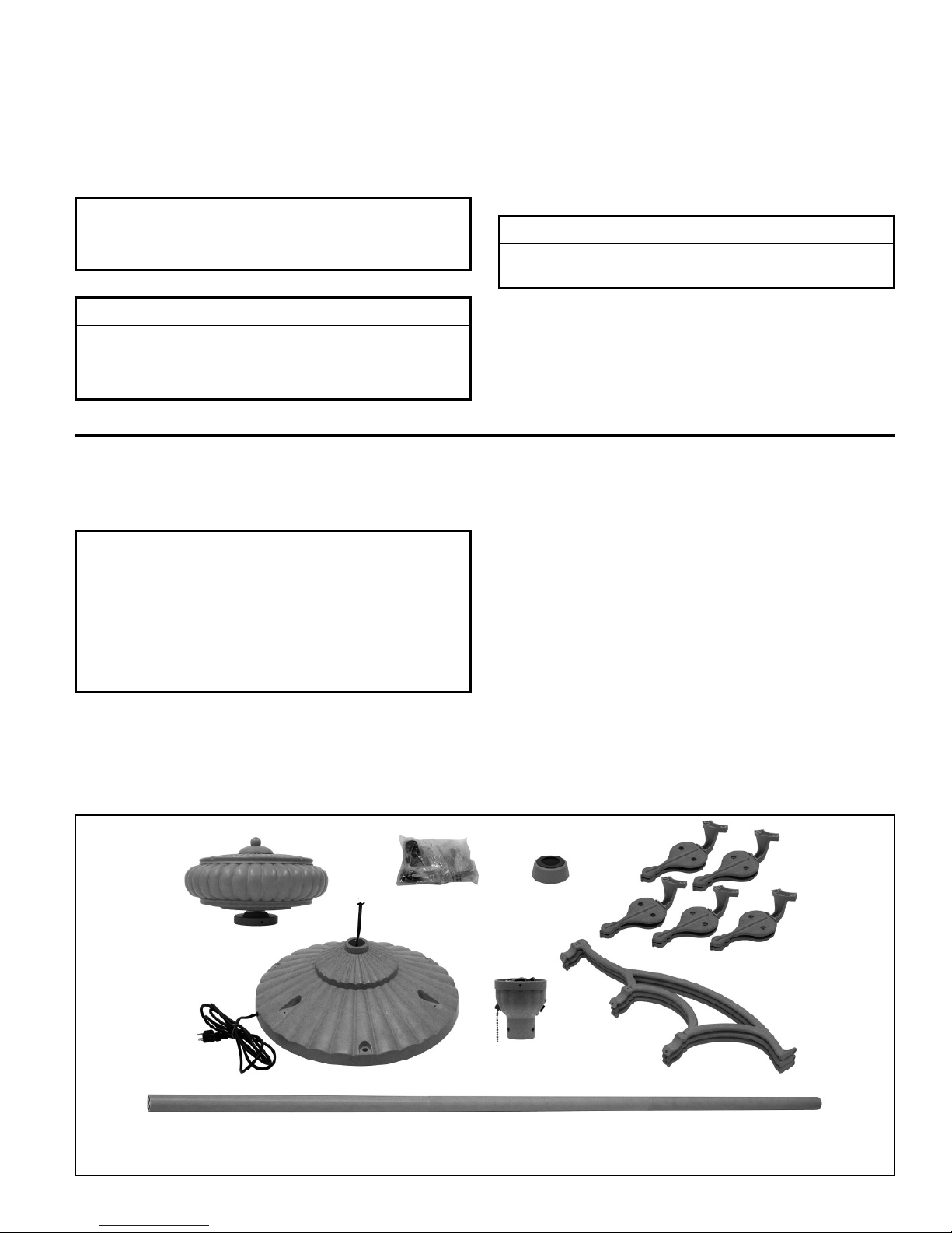
1. Check to see that you have received the following
parts:
NOTE: If you are uncertain of part description, refer to
exploded view illustration. (Figure 1, page 11)
• Fan Motor Housing
assembly
• Control Housing Support
assembly
• Base assembly
• Cover Base Connection
• Filigree (3)
• Support Shaft
• Blade Holder Arms (5)
• Blade Holder Covers (5)
• Hardware bag(s):
– Eleven ¼-20 x ⅝˝ (blade
holder to fan motor hub)
screws with lock washers
– Eleven
(blade to blade holder)
washer-head screws
3
/16-24 x 12mm
• Hardware bag (cont’d):
– Five Control Housing Support
screws
– Seven set-screws
– Ten Filigree Mounting screws
with lock washers & locknuts
– Four Filigree Base Mounting
screws with flat washers
– “T” Allen head wrench (2)
– Phillips Screwdriver, 4˝
– Three
– Three
flat washers
– Chain Coupler
– Chain Fob
– Balance Kit
⅜˝ Lag Shields
⅜˝ Lag Bolts with
Fan Motor Housing
Assembly
Base Assembly
NOTE: Blades are not included with this fan. The illustration shown is not to scale or its actual confi guration may vary.
Hardware Bag
Support Shaft
3
Cover Base
Connection
Control
Housing
Support
Assembly
Blade Holder Arms &
Blade Holder Covers
Filigree
FP920 – TORRENTO
®
Electrical Requirements
Your new Pedestal fan will require a grounded electrical
supply line of 120 volts AC, 60 Hz, 15 amp circuit. Use
Only On GFCI Protected Receptacles. DO NOT Use An
Extension Cord! The fan base must be securely anchored
and filigree set assembled.
▲
WARNING
Turning off wall switch is not sufficient. To avoid
possible electrical shock, be sure electricity is turned
off at the main fuse box before wiring. All wiring must
be in accordance with National and Local codes and the
Pedestal fan must be properly grounded as a precaution
against possible electrical shock.
CAUTION
To reduce the risk of personal injury, this product must
be SECURED as described on page 8.
CAUTION
To reduce the risk of electric shock, connect ONLY to an
outlet provided with a Ground Fault Circuit Interrupting
device.
How to Assemble Your Pedestal Fan
1. Prior to assembly, set aside and save the hardware
bag(s) packed in the packing.
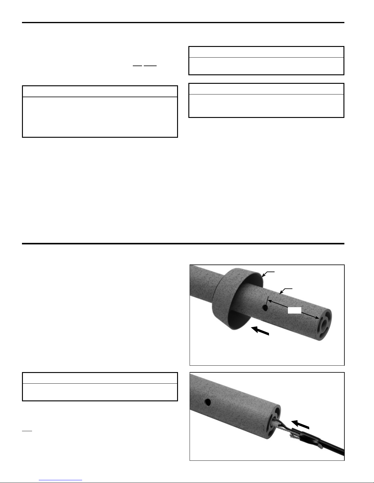
2. Assemble the Cover Base Connection onto lower part of
the Support Shaft. (Figure 1)
INSTALLATION NOTE
Cord and wires are to be fed through end of shaft that
has holes located 2¾˝ from end of shaft. Figure 2
3. Route the cord attached to (Base Assembly) wire
through the bottom part of the Support Shaft. (Figure 2)
Pull cord through Shaft until wires are completely through
the Shaft.
Cover Base
Connection
Support Shaft
2¾˝
Figure 1
Figure 2
4
FP920 – TORRENTO
How to Assemble Your Pedestal Fan (cont’d)
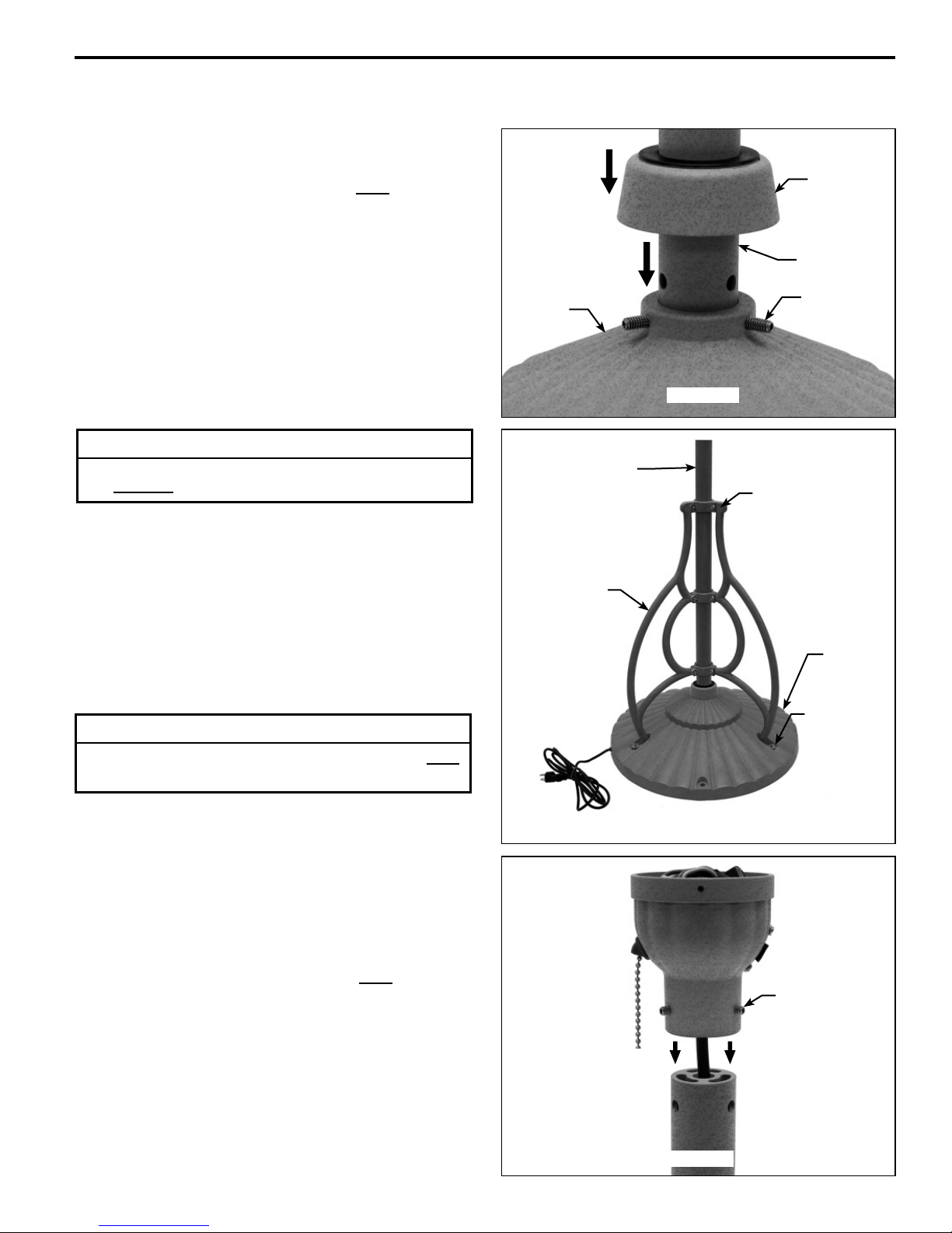
4. Assemble Support Shaft with Cover Base Connection
and set-screws (3) onto the Base Assembly. (Figure 3)
®
IMPORTANT NOTE: Be sure to ALIGN both the Support
Shaft holes (3) with the Base Assembly holes (3) to insure
proper mounting with set-screws provided. Do NOT overtighten!
NOTE: Periodically check Base Assembly hardware and
re-secure if necessary. (See Maintenance, page 8)
▲
WARNING
To reduce the risk of personal injury or property damage,
fan CANNOT be operated without Filigree set installed.
5. Assemble Filigree (set of three) onto the Base and
Support Shaft with mounting (socket-head) screws, spring
lock washers and nylon-inserted locknuts provided. Use
caution when assembling the Filigree onto the Shaft (to
prevent scratching of finish). (Figure 4)
Base
Assembly
Support Shaft
Filigree (3)
Cover Base
Connection
Support
Shaft
Set Screw
(3)
Figure 3
Filigree Socket
Head Screws with
Lockwashers &
Locknuts (9 places)
NOTE: Periodically check Filigree hardware and re-
secure if necessary. (see Maintenance, page 8)
CAUTION
To Reduce The Risk Of Personal Injury, DO NOT
Climb Pole!
6. Route wire through Control Housing Support Assembly
from Support Shaft. (Figure 5)
7. Assemble Control Housing Support Assembly and setscrews (3) onto the top of Support Shaft. (Figure 5)
IMPORTANT NOTE: Be sure to ALIGN both the Control
Housing Support Assembly holes (3) with the Support
Shaft holes (3) to insure proper mounting with set-screws
provided. Do NOT over-tighten!
NOTE: Periodically check Control Housing Support
Assembly hardware and re-secure if necessary. (see
Maintenance, page 8)
Base
Assembly
Filigree Base
Screws,
Flatwashers &
Lockwashers
(3 places)
Figure 4
Set Screw (3)
Figure 5
5
 Loading...