

Fanimation The Zonix, The Zonix FP4640**-220 Owner's Manual
™
The Zonix
Wet Location Ceiling Fan
Model No. FP4640**-220
OWNER’S MANUAL
READ AND SAVE THESE INSTRUCTIONS
Net Weight 6.7 kg (14.6 lbs)
Important Safety Instructions
WARNING: To avoid fire, shock and serious personal injury, follow these instructions.
1. Read your owner’s manual and safety information before installing your new fan. Review the accompanying assembly diagrams.
2. Before servicing or cleaning unit, switch power off at service panel and lock service panel disconnecting means to prevent power
from being switched on accidentally. When the service disconnecting means cannot be locked, securely fasten a warning device, such
as a tag, to the service panel.
3. Be careful of the fan and blades when cleaning, painting, or working near the fan. Always turn off the power to the ceiling fan before
servicing.
4. Do not insert anything into the fan blades while the fan is operating.
5. Do not operate reversing switch until fan blades have come to a complete stop.
6. Do not dispose of electrical appliances as unsorted municipal waste, use separate collection facilities.
7. Contact your local government for information regarding the collection systems available.
8. If electrical appliances are disposed of in landfills or dumps, hazardous substances can leak into the groundwater and get into the
food chain, damaging your health and well-being.
9. This appliance is not intended for use by persons (including children) with reduced physical, sensory or mental capabilities, or lack
of experience and knowledge, unless they have been given supervision or instruction concerning use of the appliance by a person
responsible for their safety.
10. Children should be supervised to ensure that they do not play with the appliance.
Additional Safety Instructions
1. To avoid possible shock, be sure electricity is turned off at the fuse box before wiring, and do not operate fan without blades.
2. All wiring and installation procedures must comply with AS/NZS 3000 Wiring Rules and any local regulations. The ceiling fan
must be grounded as a precaution against possible electrical shock. Electrical installation must be made by a licensed electrician.
3. The fan base must be securely mounted and capable of reliably supporting at least 27kg. See page 4 of owner’s manual for support
requirements.
4. The fan must be mounted with the fan blades at least 2.1 meter from the floor to prevent accidental contact with the fan blades.
5. Follow the recommended instructions for the proper method of wiring this ceiling fan.
6. This fan is Not suitable for use with solid-state speed controls.
WARNING: This product is designed to use only those parts supplied with this product and/or accessories designated specifically for
use with this product. Using parts and/or accessories not designated for use with this product will void your warranty and could result in
personal injury or property damage.
WARNING: To reduce the risk of personal injury, do not bend the blade bracket (flange or blade holder) when installing the brackets,
balancing the blades, or cleaning the fan. Do not insert foreign objects in between rotating fan blades.
WARNING:
The contact distance in all poles must be 3mm minimum.
This fan MUST be installed with an easily accessible isolating
device to disconnect all poles of the fan from the main supply.
Energy Effi cient Use of Ceiling Fans . . . . . . . . . . . . . . . . . . . . . . . . . . . . 4
Electrical and Structural Requirements . . . . . . . . . . . . . . . . . . . . . . . . . .4
How to Assemble This Ceiling Fan . . . . . . . . . . . . . . . . . . . . . . . . . . . . . .5
How to Hang This Ceiling Fan . . . . . . . . . . . . . . . . . . . . . . . . . . . . . . . . . .6
How to Wire This Ceiling Fan . . . . . . . . . . . . . . . . . . . . . . . . . . . . . . . . . .7
Installing the Canopy Housing . . . . . . . . . . . . . . . . . . . . . . . . . . . . . . . . .8
Table of Contents
Mounting the Fan Blades and Cover Switch Assembly. . . . . . . . . . . . . 8
3. . . . . . . . . . . . . . . . . . . . . . . . . . . . . . . . . . . . . . . snoitcurtsnI gnikcapnU
Maintenance . . . . . . . . . . . . . . . . . . . . . . . . . . . . . . . . . . . . . . . . . . . . . . . .9
Blade Cleaning . . . . . . . . . . . . . . . . . . . . . . . . . . . . . . . . . . . . . . . . . . . . . .9
Parts List . . . . . . . . . . . . . . . . . . . . . . . . . . . . . . . . . . . . . . . . . . . . . . . . . 10
Exploded-View Illustration. . . . . . . . . . . . . . . . . . . . . . . . . . . . . . . . . . . .11
Trouble Shooting . . . . . . . . . . . . . . . . . . . . . . . . . . . . . . . . . . . . . . . . . . .12
This Manual is Designed to Make it as Easy as Possible
to Assemble, Install, Operate, and Maintain This Ceiling Fan
Tools Needed for Assembly Materials
• One Phillips head screwdriver
(supplied)
• One stepladder
▲
WARNING
This fan must be installed be a licensed electrician.
• One small blade
screwdriver
• One wire stripper
Wiring and connectors must be of type required by
local regulations. The minimum wire would be a 3conductor (2-wire with ground).
Unpacking Instructions
For your convenience, check-off each step. As each step is completed, place a check mark. This will ensure that all
steps have been completed and will be helpful in fi nding your place should you be interrupted.
▲
WARNING
Do not install or use fan if any part is damaged or
missing. This product is designed to use only those
parts supplied with this product and/or any accessories
designated specifically for use with this product by
Fanimation. Substitution of parts or accessories not
designated for use with this product could result in
personal injury or property damage.
IF ANY PART IS DAMAGED OR MISSING,
CALL: 1300 469 326
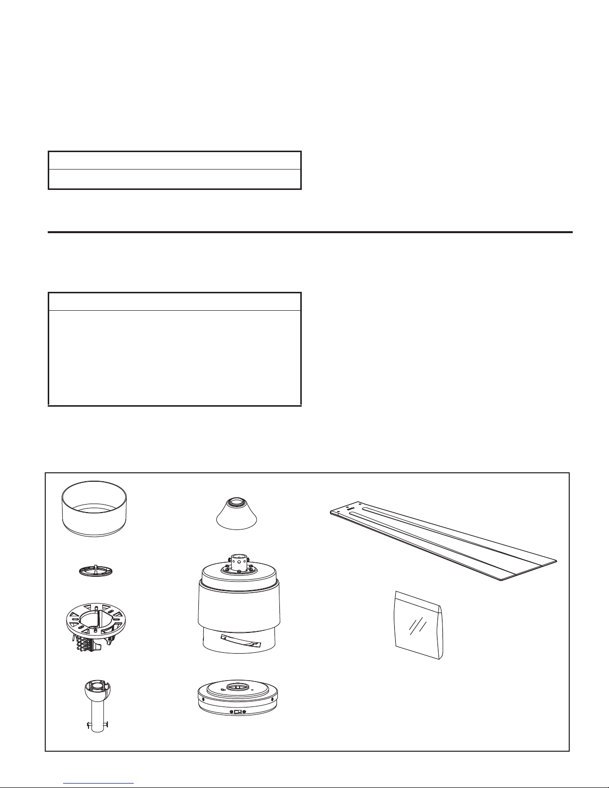
1. Check to see that you have received the following
parts:
• Fan Motor Assembly
• Downrod/Hanger Ball
Assembly
• Hanger Bracket
• Ceiling Canopy
• Canopy Screw Cover
• Motor Coupling Cover
• Switch Cup Cover Assembly
Blade Set •
• Hardware bags:
– 3/16-24 x 13 mm (blade to motor hub)
washer-head screws & fiber washers
– Phillips screwdriver, 10cm
– Blade Balance Kit
NOTE: If you are uncertain of part description, refer to
exploded view illustration. (Figure 1, page 11)
Ceiling Canopy
Canopy
Screw Cover
Hanger Bracket
Downrod/
Hanger Ball
Assembly
Motor Coupling Cover
Fan Motor Assembly
Switch Cup Cover Assembly
Blade Set
Hardware Bags
3
snaF gnilieC fo esU tneic iffE ygrenE
Ceiling fan performance and energy savings rely
heavily on the proper installation and use of the ceiling
fan. Here are a few tips to ensure efficient product
performance.
Choosing the Appropriate Mounting Location
Ceiling fans should be installed, or mounted, in the middle
of the room and at least 2.1 m above the floor and 50 cm
from the walls. If ceiling height allows, install the fan
2.4-2.7 m above the floor for optimal airflow. Consult your
Fanimation Retailer for optional mounting accessories.
Turn Off When Not in the Room
Ceiling fans cool people, not rooms. If the room is
unoccupied, turn off the ceiling fan to save energy.
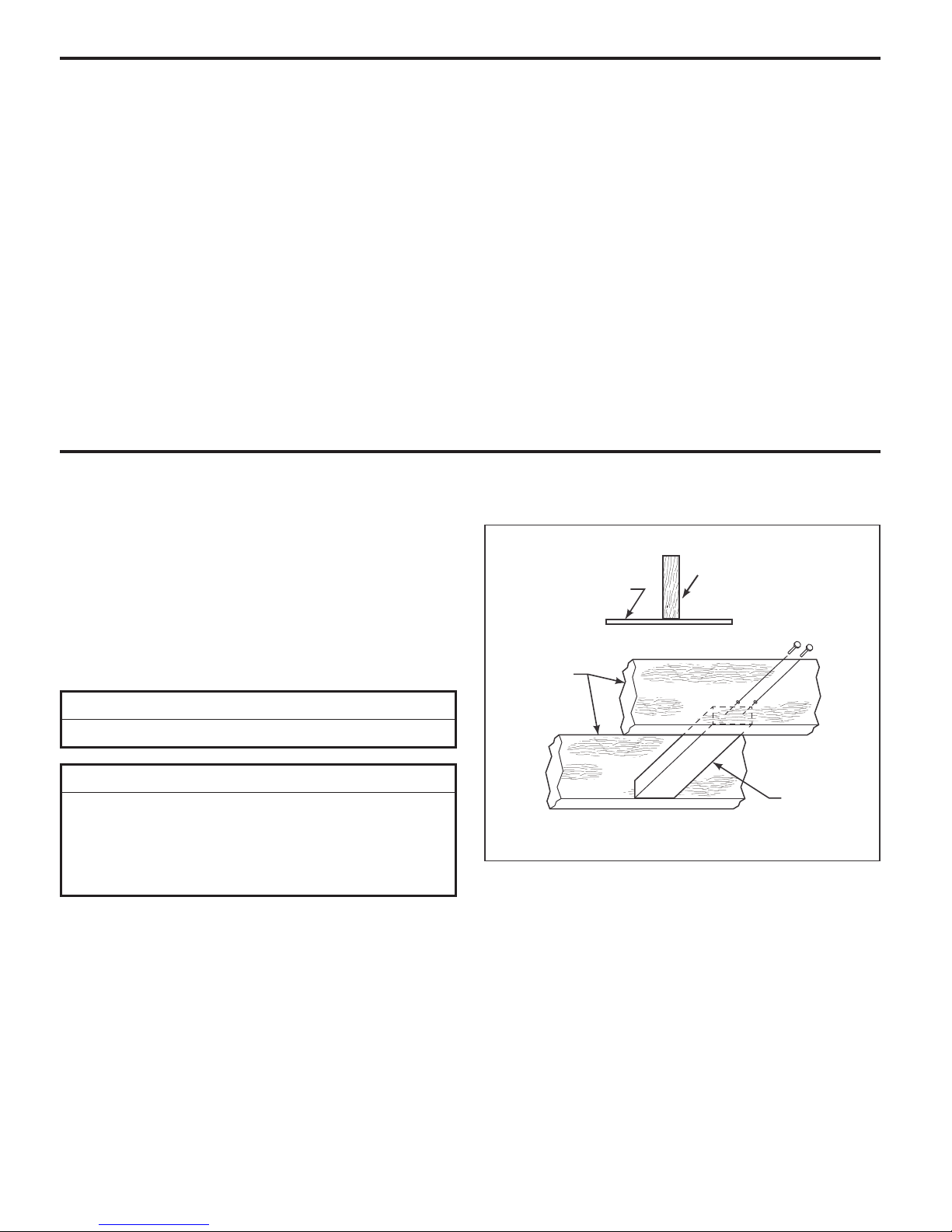
Electrical and Structural Requirements
This new ceiling fan will require a grounded electrical supply
line of 220-240 volts AC, 50 Hz circuit. The hanger
bracket must be securely anchored and capable of
supporting a load of least 27kg. If your fan is to replace an
existing ceiling light fixture, turn electricity off at the main
fuse box at this time and remove the existing light fixture.
Figure 1 depicts a typical structural configuration that may
be used for securely mounting the fan.
▲
WARNING
This fan must be installed by a licensed electrician.
Using the Ceiling Fan Year Round
Summer Season: Use the ceiling fan in the counter-
clockwise direction. The airflow produced by the ceiling
fan creates a wind-chill effect, making you “feel” cooler.
Select a fan speed that provides a comfortable breeze,
lower speeds consume less energy.
Winter Season: Reverse the motor and operate the ceiling
fan at low speed in the clockwise direction. This produces
a gentle updraft, which forces warm air near the ceiling
down into the occupied space. Remember to adjust your
air conditioner when using your ceiling fan-additional energy
and dollar savings could be realized with this simple step!
Ceiling
Ceiling
Ceiling
Joists
Joists
▲
WARNING
Turning off wall switch is not sufficient. To avoid
possible electrical shock, be sure electricity is turned
off at the main fuse box before wiring. All wiring must
be in accordance with AS/NZS 3000 “The Wiring Rules”
and the ceiling fan must be properly grounded as a
precaution against possible electrical shock.
50 X 100 mm
Timber Batten
Between Joists
Figure 1
4
How to Assemble This Ceiling Fan
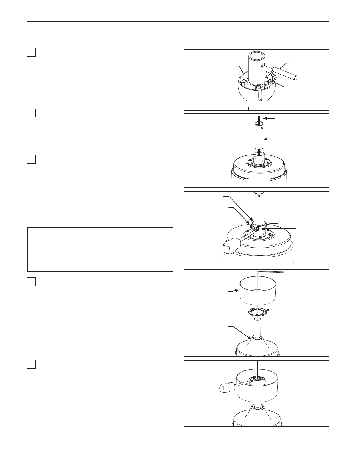
1. Remove the hanger ball by loosening the setscrew
in the hanger ball until the ball falls freely down the
downrod. Remove the pin from the downrod, then
remove the hanger ball. Retain the pin and hanger
ball for reinstallation in Step 5. (Figure 1)
2. The fan comes with green/yellow, blue, brown and
orange 2 m length wires. Separate and untwist the four
wires. Route the wires through the downrod. (Figure 2)
NOTE: You will be using either the 15 cm downrod supplied
with your fan or an optional longer downrod purchased
separately for high ceilings.
3. Loosen the two setscrews in the downrod support.
Align the clevis pin holes in the downrod with the
holes in the downrod support. Install the clevis pin
and secure with the hairpin clip. Be sure to push the
straight leg of the hairpin clip through the hole near
the end of the clevis pin until the curved portion of the
hairpin clip snaps around the clevis pin. The hairpin
clip must be properly installed to prevent the clevis
pin from working loose. Pull on the downrod to make
sure the clevis pin is properly installed. (Figure 3)
▲
WARNING
It is critical that the clevis pin in the downrod support
is properly installed and the setscrews and nuts are
securely tightened. Failure to verify that the pin and
setscrews are properly installed could result in the fan
falling.
Downrod
Support
Clevis Pin
Hanger
Ball
Pin
Setscrew
Figure 1
Green/Yellow, Blue,
brown and orange Lead
Downrod
Figure 2
Hairpin Clip
Setscrew (2)
with nut
Figure 3
4. Route wires through motor coupling cover, canopy
screw cover and ceiling canopy with open side facing
up. (Figure 4)
5. Reinstall the hanger ball on the downrod as follows.
Route the four 2 m length wires and cable through the
hanger ball. Position the pin through the two holes in
the downrod and align the hanger ball so the pin is
captured in the groove in the top of the hanger ball.
Pull the hanger ball up tight against the pin. Securely
tighten the setscrew in the hanger ball. A loose
setscrew could create fan wobble. (Figure 5)
Ceiling
Canopy
Canopy Screw
Cover
Motor
Coupling
Cover
Figure 4
Figure 5
5
 Loading...