

Page 1
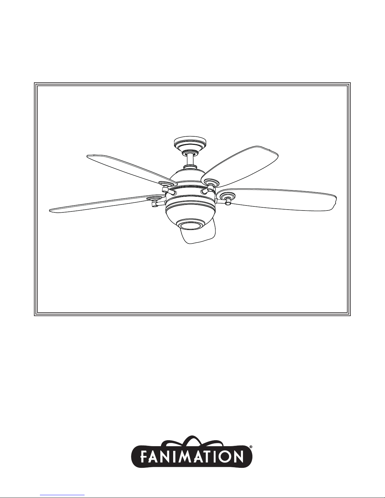
Model No. FP8000
OWNER'S MANUAL
READ AND SAVE THESE INSTRUCTIONS
The Akira
™
Ceiling Fan
Finishes: OB and PW
Net Weight 9.6 kg. (21.2 lbs.)
Page 2

2
Important Safety Instructions
WARNING: To avoid fire, shock and serious personal injury, follow these instructions.
1. Read your owner’s manual and safety information before installing your new fan. Review the accompanying assembly
diagrams.
2. Before servicing or cleaning unit, switch power off at service panel and lock service panel disconnecting means to prevent
power from being switched on accidentally. When the service disconnecting means cannot be locked, securely fasten a
warning device, such as a tag, to the service panel.
3. Be careful of the fan and blades when cleaning, painting, or working near the fan. Always turn off the power to the ceiling
fan before servicing.
4. Do not insert anything into the fan blades while the fan is operating.
5. Do not operate reversing switch until fan blades have come to a complete stop.
Ad di tiona l Saf ety I ns truct ions
1. To avoid possible shock, be sure electricity is turned off at the fuse box before wiring, and do not operate fan without
blades.
2. All wiring and installation procedures must satisfy National Electrical Codes (ANSI/ NFPA 70-1999) and Local Codes. The
ceiling fan must be grounded as a precaution against possible electrical shock. Electrical installation should be made or
approved by a licensed electrician.
3. The fan base must be securely mounted and capable of reliably supporting at least 50 lbs. (fan and accessories not to
exceed 50 lbs. or 22.7 kgs.). See page 4 of owner’s manual for support requirements. Consult a qualified electrician if in
doubt.
4. The fan must be mounted with the fan blades at least 7 feet from the floor to prevent accidental contact with the fan blades.
5. Follow the recommended instructions for the proper method of wiring your ceiling fan. If you do not have adequate
electrical knowledge or experience, have your fan installed by licensed electrician.
6. Suitable for use with solid-state speed controls.
WARNING:To reduce the risk of fire or electric shock, this fan should only be used with Fan Speed Control Part No.
UC7067RC, manufactured by Rhine Electronic Co., Ltd.
WARNING:TO REDUCE THE RISK OF SHOCK, THIS FAN MUST BE INSTALLED WITH AN ISOLATING WALL
CONTROL/SWITCH.
WARNING:This product is designed to use only those parts supplied with this product and/or accessories designated
specifically for use with this product. Using parts and/or accessories not designated for use with this product could result in
personal injury or property damage.
WARNING
:
To reduce the risk of personal injury, do not bend the blade bracket (flange or blade holder) when installing the
brackets, balancing the blades, or cleaning the fan. Do not insert foreign objects in between rotating fan blades.
LIMITED LIFETIME WARRANTY
Extends to the original purchaser of a Fanimation Fan
1. LIMITED LIFETIME MOTOR WARRANTY - If any part of your fan motor fails, due to a defect in materials or workmanship
during the lifetime of the original purchaser, Fanimation will provide the replacement part free of charge, when the defective
fan is returned to our national service center. Proof of purchase is required. Customer shall be responsible for all costs
incurred in the removal or reinstallation and shipping of the product for repairs or replacement.
2. ONE YEAR MOTOR LABOR WARRANTY - If your fan motor fails at any time within one year from the original purchase, due
to defects in materials or workmanship, labor to repair the motor will be provided free of charge at our national service
center. Purchaser will be responsible for labor charges after this one-year period. Customer shall be responsible for all
costs incurred in the removal or reinstallation and shipping of the product for repairs or replacement.
3. If any other part of your fan fails at any time within one year after original purchase, due to a defect in materials or
workmanship, we will repair, or replace, at our option, the defective part free of charge for parts and labor performed at our
national service center.
4. Because of varying climate conditions, this warranty does not cover changes in the finish, including rusting, pitting,
corroding, tarnishing, or peeling.
5. This warranty is void and does not apply to damage from improper installation, neglect, accident, misuse, exposure to
extremes of heat or humidity, or as a result of any modification to the original product.
6. All costs of removal and reinstallation of the fan are the sole responsibility of the owner of the fan and not the store that
sold the fan or Fanimation.
7. Fanimation reserves the right to modify or discontinue any product at any time and may substitute any part under this
warranty.
8. Under no circumstances may a fan be returned without prior authorization from Fanimation. The receipt of purchase must
accompany authorized returns and must be sent freight prepaid to Fanimation. The fan to be returned must be properly
packed to avoid damage in transit; Fanimation will not be responsible for any damage resulting from improper packaging.
9. It is understood that any repair or replacement is the exclusive remedy available from Fanimation. There is no other
expressed or implied warranty. Fanimation hereby disclaims any and all implied warranties, including, but not limited to
those of merchantability and fitness for a particular purpose to the extent permitted by law. Some states do not allow
limitations on implied warranties. Fanimation will not be liable for incidental, consequential, or special damages arising out
of or in conjunction with product use or performance, except as may otherwise be accorded by law. This warranty gives you
special legal rights and you may also have other rights that vary from state to state.
10.A certain amount of wobble is normal and should not be considered a problem or a defect.
Unpacking Instructions . . . . . . . . . . . . . . . . . . . . . . . . . . . . . . .3
Energy Efficient Use of Ceiling Fans . . . . . . . . . . . . . . . . . . . . .4
Electrical and Structural Requirements . . . . . . . . . . . . . . . . . .4
How to Assemble Your Ceiling Fan . . . . . . . . . . . . . . . . . . . . . .5
How to Hang Your Ceiling Fan . . . . . . . . . . . . . . . . . . . . . . . . . .6
How to Wire Your Ceiling Fan . . . . . . . . . . . . . . . . . . . . . . . . . .7
How to Install Your Canopy Housing . . . . . . . . . . . . . . . . . . . .8
How to Assembly the Blades & Light Kit . . . . . . . . . . . . . . . . .9
How to Operate Your Ceiling Fan . . . . . . . . . . . . . . . . . . . . . .11
Maintenance . . . . . . . . . . . . . . . . . . . . . . . . . . . . . . . . . . . . . . . .12
How to Clean Your Ceiling Fan Blades . . . . . . . . . . . . . . . . . .12
Trouble Shooting . . . . . . . . . . . . . . . . . . . . . . . . . . . . . . . . . . . .13
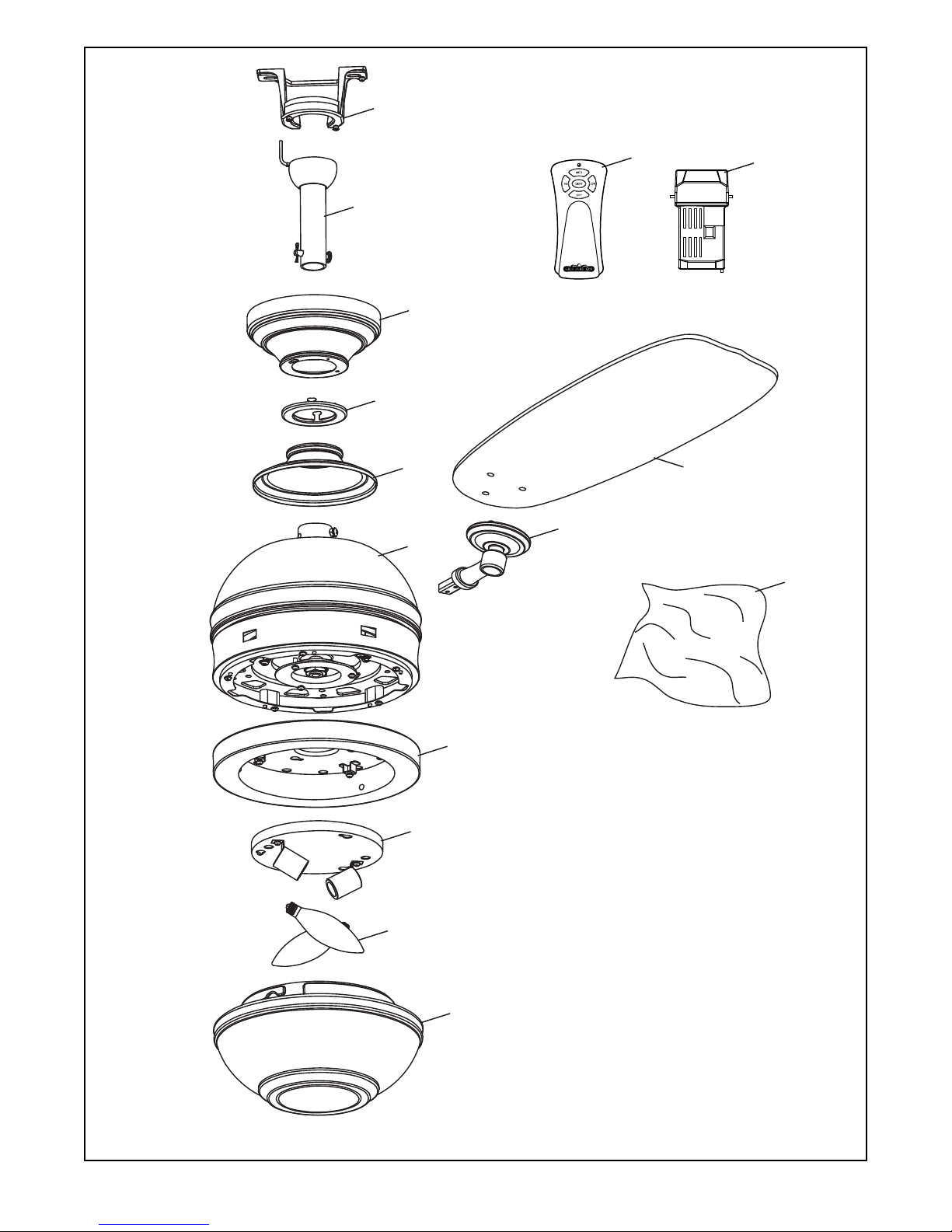
Parts List . . . . . . . . . . . . . . . . . . . . . . . . . . . . . . . . . . . . . . . . . .14
Exploded-View Illustration . . . . . . . . . . . . . . . . . . . . . . . . . . . .15
Table of Contents
Page 3
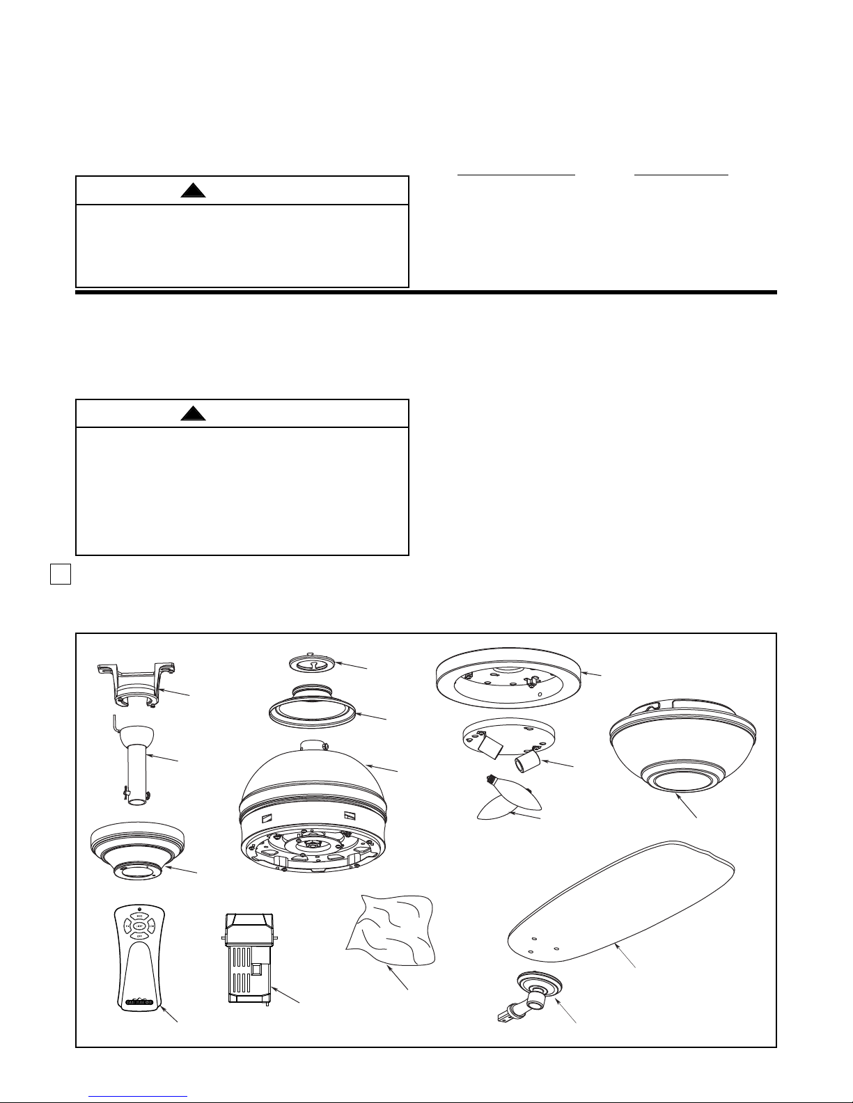
1. Check to see that you have received the following parts:
NOTE:
If you are uncertain of part description, refer to
exploded view illustration.
This Manual Is Designed to Make it as Easy as Possible for You to Assemble,
Install, Operate and Maintain Your Ceiling Fan
Tools Needed for Assembly
• One Phillips head screwdriver
• One stepladder
• Three wire connectors (supplied)
3
Installed Wire Length Wire Size A.W.G.
41.tf 05 ot pU
21.tf 001-05
Unpacking Instructions
For your convenience, check-off boxes are provided next to each step. As each step is completed, place a check
mark in the box. This will insure that all steps have been completed and will be helpful in finding your place should
you be interrupted.
Before assembling your ceiling fan, refer to section
on proper method of wiring your fan (page 4). If you
feel you do not have enough wiring knowledge or
experience, have your fan installed by a licensed
electrician.
Do not install or use fan if any part is damaged or
missing. This product is designed to use only those
parts supplied with this product and/or any
accessories designated specifically for use with this
product by Fanimation. Substitution of parts or
accessories not designated for use with this product
by Fanimation could result in personal injury or
property damage.
WARNING
!
WARNING
!
• One wire stripper
• One 1/4” blade
screwdriver
Materials
Wiring outlet box and box connectors must be of type
required by the local code. The minimum wire would be a
3-conductor (2-wire with ground) of the following size:
NOTE:
Place the parts from the loose parts bags in a small
container to keep them from being lost. If any parts are
missing contact your local retailer.
• Fan Motor Assembly
• Hanger Bracket Assembly with
screws
• Downrod/Hanger Ball Assembly
• Ceiling Canopy
• Canopy Screw Cover Assembly
• Motor Coupling Cover Assembly
• Blade Arm Set (5)
• Blade Set (5)
• Housing Light Kit Assembly
• Socket Plate Assembly
• Two 60W Candelabra Light Bulbs
• Glass
• C24 Remote Control
• Receiver Unit
• Hardware bags:
– 3/16-24 x 7.5mm
(blade to blade holder)
Washer Head Screw
– 3/16” Fiber Washer
(blade to blade holder)
– 1/4”-20 x 14mm
(blade arm to motor)
Pan Head Screw
– Phillips Screwdriver, 4�
– Four Wire Connectors
– Balance Kit
HANGER
BRACKET
ASSEMBLY
W/SCREWS
DOWNROD/
HANGER BALL
ASSEMBLY
CEILING
CANOPY
C24 REMOTE
CONTROL
RECEIVER
UNIT
CANOPY
SCREW
COVER
ASSEMBLY
MOTOR
COUPLING
COVER
FAN MOTOR
ASSEMBLY
HARDWARE BAG
SOCKET
PLATE
ASSEMBLY
TWO 60-WATT
CANDELABRA
LIGHT BULBS
BLADE ARM SET (5)
HOUSING
LIGHT KIT
ASSEMBLY
GLASS
BLADE SET (5)
Page 4
4
Energy Efficient Use of Ceiling Fans
Ceiling fan performance and energy savings rely
heavily on the proper installation and use of the
ceiling fan. Here are a few tips to ensure efficient
product performance.
Choosing the Appropriate Mounting Location
Ceiling fans should be installed, or mounted, in the
middle of the room and at least 7 feet above the floor
and 18 inches from the walls. If ceiling height allows,
install the fan 8 - 9 feet above the floor for optimal
airflow. Consult your Fanimation Retailer for optional
mounting accessories.
Turn Off When Not in the Room
Ceiling fans cool people, not rooms. If the room is
unoccupied, turn off the ceiling fan to save energy.
Using the Ceiling Fan Year Round
Summer Season: Use the ceiling fan in the
counterclockwise direction. The airflow produced by
the ceiling fan creates a wind-chill effect, making you
“feel” cooler. Select a fan speed that provides a
comfortable breeze, lower speeds consume less
energy.
Winter Season: Reverse the motor and operate the
ceiling fan at low speed in the clockwise direction.
This produces a gentle updraft, which forces warm air
near the ceiling down into the occupied space.
Remember to adjust your thermostat when using your
ceiling fan - additional energy and dollar savings
could be realized with this simple step!
Electrical and Structural Requirements
If your fan is to replace an existing light fixture, turn
electricity off at the main fuse box at this time and
remove the existing light fixture.
Your new ceiling fan will require a grounded electrical
supply line of 120 volts AC, 60 Hz, 15 amp circuit.
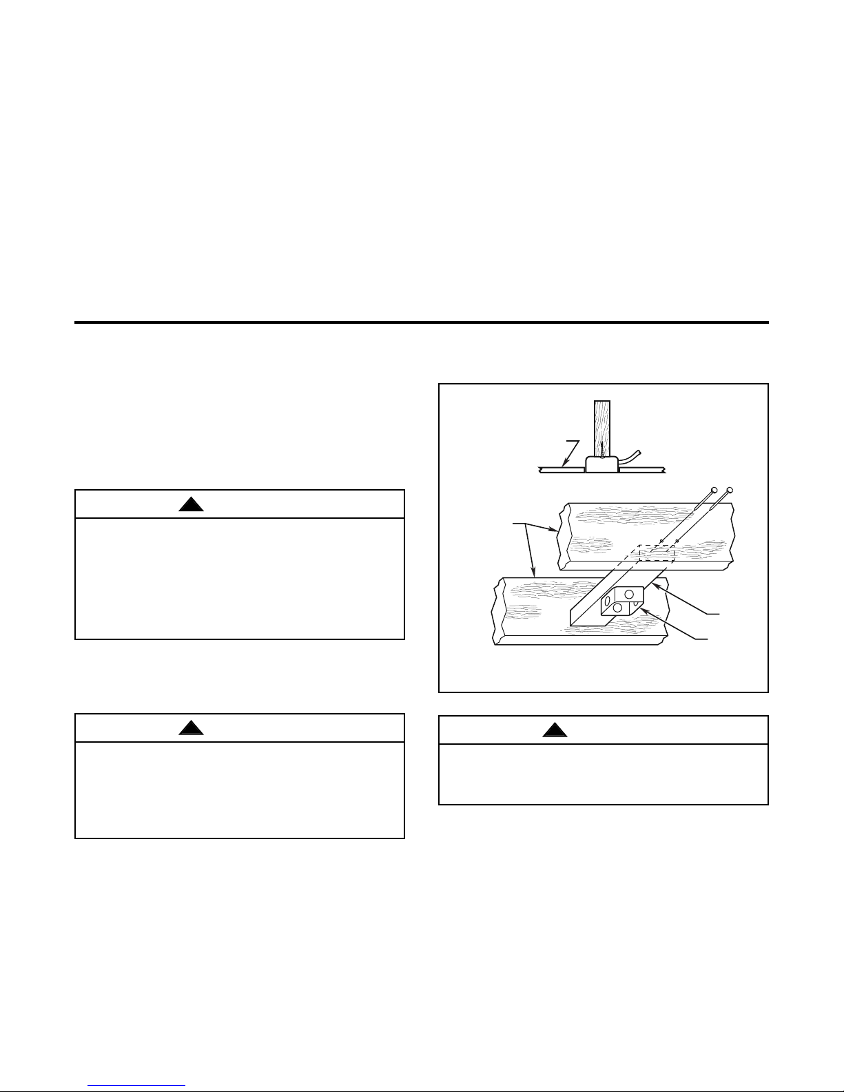
The outlet box must be securely anchored and
capable of withstanding a load of at least 50 lbs.
Figure 1 depicts different structural configurations
that may be used for mounting the outlet box.
To avoid fire or shock, follow all wiring instructions
carefully. Any electrical work not described in these
instructions should be done or approved by a
licensed electrician.
Turning off wall switch is not sufficient. To avoid
possible electrical shock, be sure electricity is
turned off at the main fuse box before wiring. All
wiring must be in accordance with National and
Local codes and the ceiling fan must be properly
grounded as a precaution against possible electrical
shock.
WARNING
!
WARNING
!
To reduce the risk of fire, electrical shock, or
personal injury, mount fan to outlet box marked
acceptable for fan support of 22.7 kg (50 lbs) or less.
Use screws supplied with outlet box. Most outlet
boxes commonly used for support of light fixtures
are not acceptable for fan support and may need to
be replaced. Consult a qualified electrician if
in doubt.
WARNING
!
Figure 1
CEILING
CEILING JOIST
2" x 4"
OUTLET BOX
Page 5
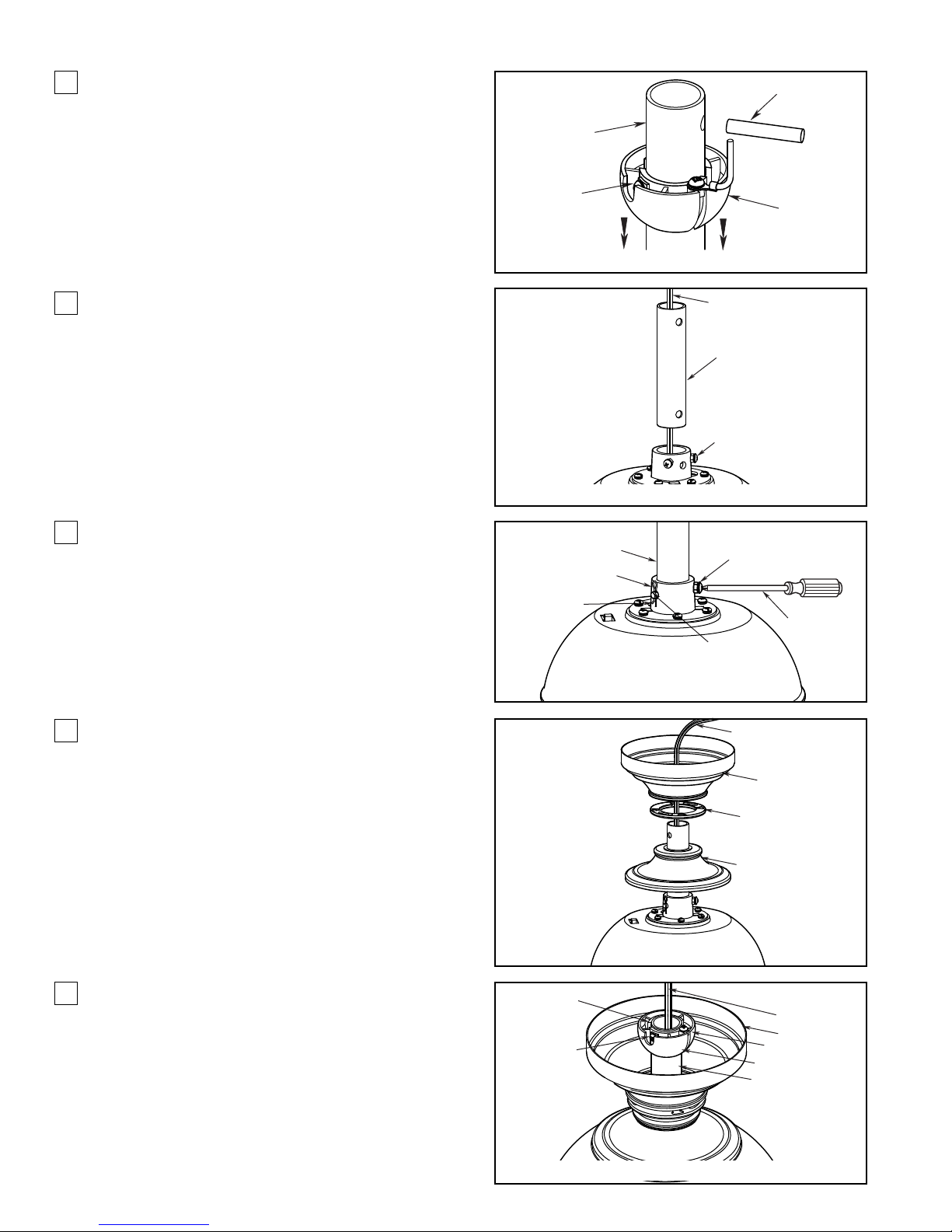
Figure 1
5
How to Assemble Your Ceiling Fan
1. Remove the hanger ball portion from the
downrod/hangerball assembly by loosening the set
screw in the hanger ball until the ball falls freely
down the downrod. Remove the pin from the
downrod, then remove the hanger ball. Retain the
pin and hanger ball for reinstallation in Step 4
(Figure 1).
2. Loosen the two set screws in the downrod support.
Route black, blue and white lead wires through the
downrod (Figure 2).
3. Position downrod support and align the clevis pin
holes in both parts. Install the clevis pin and secure
with the hairpin clip. Tighten the two set screws
and locking nuts in the downrod support (Figure 3).
4. Route wires through motor coupling cover, canopy
screw cover and canopy (Figure 4).
5. Reinstall the hanger ball on t he downr od as
follows.Route the three 80-inch wires through the
hanger ball. Position the pin through the two holes
in the downrod and align the hanger ball so the pin
is captured in the groove in the top of the hanger
ball. Pull the hanger ball up tight against the pin.
Securely tighten the set screw in the hanger ball.
A loose set screw could create fan wobble
(Figure 5).
Figure 5
Figure 3
Figure 4
Figure 2
DOWNROD
SET SCREW
DOWNROD
DOWNROD SUPPORT
HAIRPIN CLIP
PIN
BLACK, BLUE AND
WHITE LEADS
DOWNROD
SET SCREWS AND
LOCKING NUTS (2)
SET SCREWS AND
LOCKING NUTS (2)
CLEVIS PIN
HANGER BALL
SCREWDRIVER
SET SCREW
PIN
BLACK, BLUE &
WHITE LEADS
CANOPY
CANOPY COVER
MOTOR COUPLING
COVER
BLACK, BLUE &
WHITE LEADS
CANOPY
GROOVE
HANGER BALL
DOWNROD
Page 6
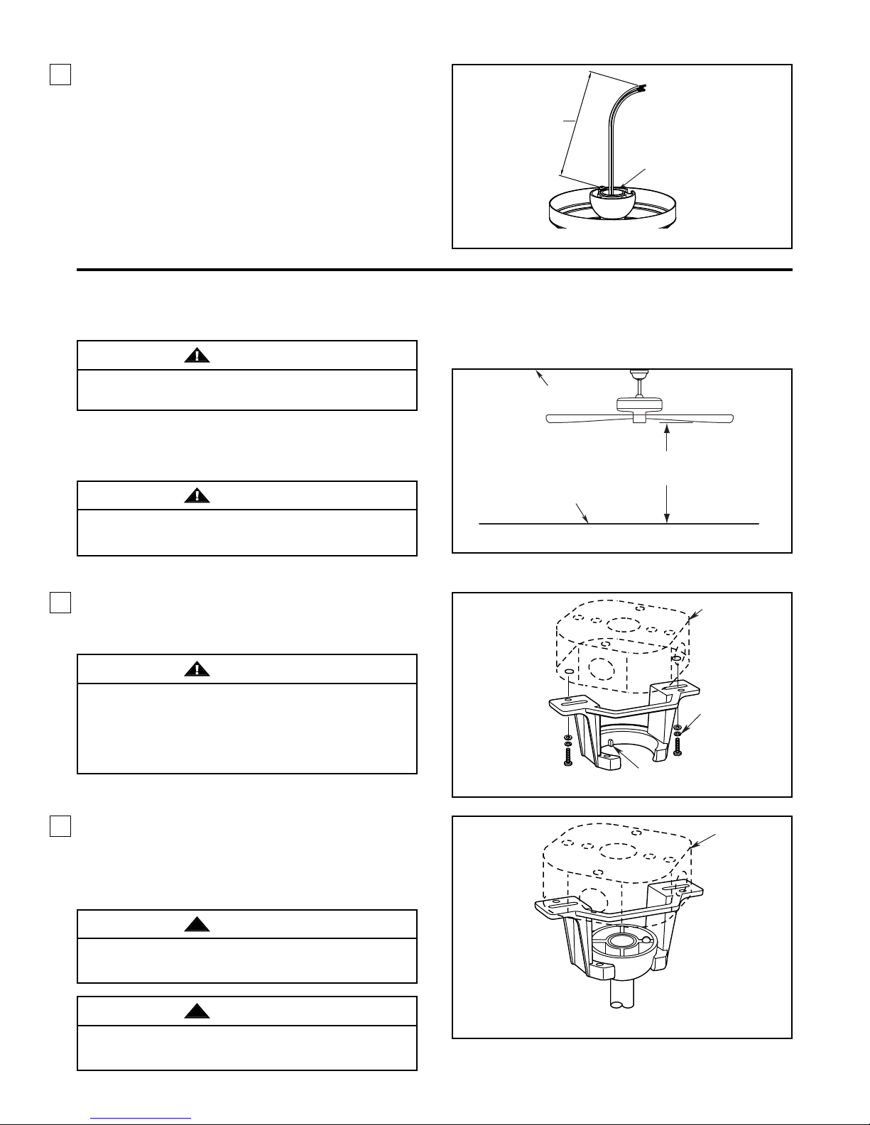
How to Assemble Your Ceiling Fan (continued)
6. Cut off excess lead wire approximately 6 to 9
inches above top of the top of the downrod. Strip
insulation off 1/2-inch from the end of each lead
wire (Figure 6).
How to Hang Your Ceiling Fan
WARNING
6 TO 9
INCHES
DOWNROD
Figure 6
To avoid possible fire or shock, be sure electricity is
turned off at the main fuse box before hanging.
NOTE:
contact a licensed electrician for advise, as it must be
grounded for safe operation.
If you are not sure if the outlet box is grounded,
WARNING
The fan must be hung with at least 7' of clearance
from floor to blades (Figure 1).
1. Securely attach the hanger bracket to the outlet
box using the outlet box screws and washers
supplied with the outlet box (Figure 2).
WARNING
The outlet box must be securely anchored. Hanger
bracket must seat firmly against outlet box. If the outlet
box is recessed, remove wall board until bracket
contacts box. If bracket and /or outlet box are not
securely attached, the fan could wobble or fall.
CEILING
FLOOR
Figure 1
Figure 2
NO
LESS THAN
7 FEET
TAB
OUTLET BOX
SCREW (2)
(Supplied with
Outlet Box)
2. Carefully lift the fan and seat the downrod/hanger
ball assembly on the hanger bracket that was just
attached to the outlet box. Be sure the groove in
the ball is lined up with tab on the hanger bracket
(Figure 3).
!
WARNING
Failure to seat tab in groove could cause damage to
electrical wires and possible shock or fire hazard.
!
WARNING
To avoid possible shock, do not pinch wires between
the hanger ball assembly and the hanger bracket.
OUTLET BOX
Figure 3
6
Page 7
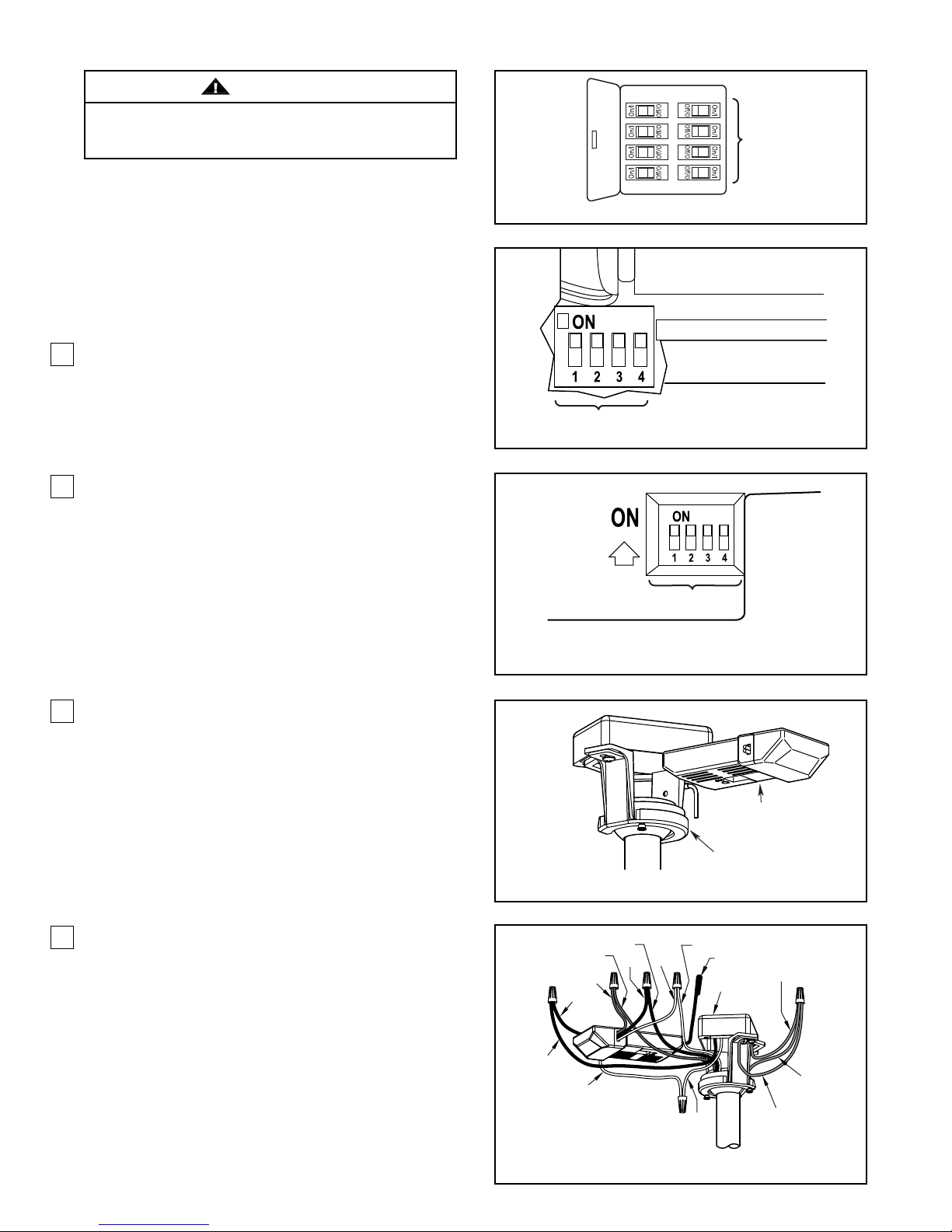
How to Wire Your Ceiling Fan
WARNING
To avoid possible electrical shock, be sure electricity
is turned off at the main fuse box before hanging
(Figure 1).
MAIN FUSE BOX
NOTE:
If you are not sure if the outlet box is
grounded, contact a licensed electrician for advice, as
it must be grounded for safe operation.
NOTE:
The hand-held remote included with this fan
has 16 different code combinations. To prevent
possible interference from or to other remote units,
simply change the combination code in your
transmitter and receiver.
1. To set the transmitter code, remove battery cover
by pressing firmly below arrow and sliding cover
off. Slide code switches to your choice of up or
down position. Factory setting is all up. Do not use
this position. With a small screwdriver or ball point
pen slide firmly up or down. Replace battery cover
on the transmitter (Figure 2).
2. To set the receiver unit code, slide code switches
to the same positions as set on your transmitter
(Figure 3).
REMOTE
CONTROL
DETAIL
TRANSMITTER CODES
RECEIVER
UNIT
DETAIL
Figure 1
9V BATTERY
Figure 2
CODE SWITCHES
3. Slide the receiver unit into the open end of the
hanger bracket (Figure 4).
4. Connect green wires from hanger bracket and
hanger ball to bare (ground) wire using wire
connector supplied. Connect black wire from
receiver unit marked “AC IN L” to black supply wire
using wire connector supplied. Connect white wire
from receiver unit marked “AC IN N” to white supply
wire using wire connector supplied. Connect white
wire from receiver unit marked “TO MOTOR N” to
white wire from fan using wire connector supplied
with receiver. Connect black wire from receiver unit
marked “TO MOTOR L” to black wire from fan
using wire connector supplied. Lastly, connect blue
wire from receiver to the blue fan light wire using
wire connector supplied. Position all connected
wires and receiver antenna to allow installation of
ceiling canopy (Figure 5).
Figure 3
RECEIVER UNIT
HANGER BRACKET
Figure 4
BLACK
BLACK to Motor
BLUE to Light
BLUE
BLACK
WHITE
BLACK
WHITE
WHITE to Motor
BLACK - ANT
LISTED
OUTLET BOX
WHITE
GREEN WIRE
(Ground)
GREEN WIRE
(Ground from
hanger ball)
GREEN WIRE (Ground
from hanger bracket)
Figure 5
7
Page 8
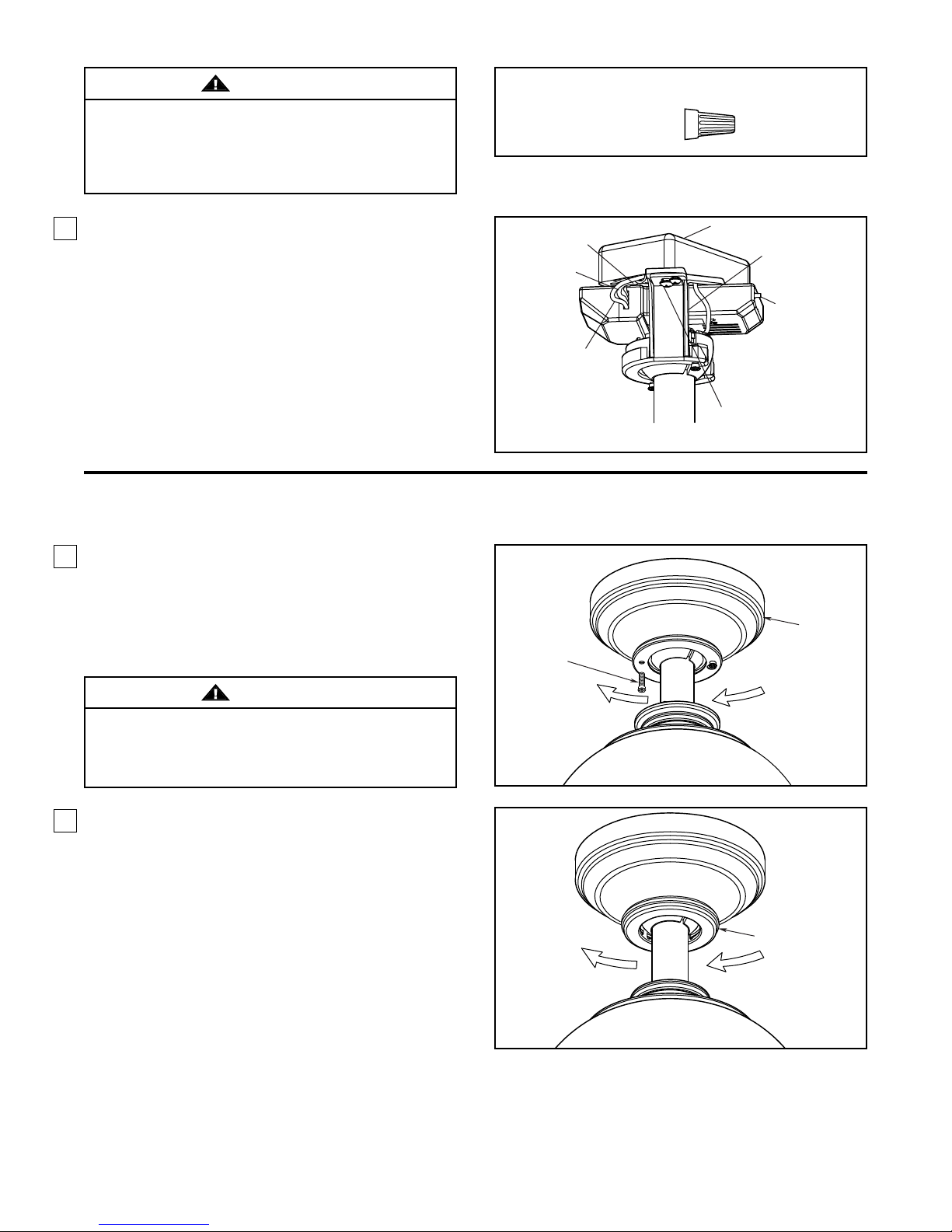
8
How to Wire Your Ceiling Fan (continued)
Check to see that all connections are tight, including
ground, and that no bare wire is visible at the wire
connectors except for the ground wire. Do not
operate fan until the blades are in place. Noise and
motor damage could result.
WARNING
Figure 6
5. After connections have been made, turn leads
upward and carefully push leads into the outlet box,
with the white and green leads to one side of the
box and the black leads towards the other side.
The wires should be spread apart with the
grounded conductor and the equipment-grounding
conductor on one side of the outlet box and the
ungrounded conductor on the other side of the
outlet box (Figure 6).
Figure 1
Figure 2
1. Remove one of the two shoulder screws in the
hanger bracket. Loosen the second shoulder screw
without fully removing it. Assemble canopy by
rotating key slot in canopy over shoulder screw in
hanger bracket. Tighten shoulder screw. Fully
assemble and tighten second shoulder screw that
was previously removed (Figure 1).
2. Securely attach and tighten the canopy screw
cover over the shoulder screws in the hanger
bracket utilizing the keyslot twist-lock feature
(Figure 2).
How to Install Your Canopy Housing
To avoid possible fire or shock, make sure that the
electrical wires are completely inside the canopy
housing and not pinched between the housing and
the ceiling.
WARNING
WHITE
BLACK
BLUE
HARDWARE USED:
CONNECTORS
x 6WIRE
LISTED OUTLET BOX
GREEN - Ground Wire
From Hanger Ball
BLACK-ANT
GREEN - Ground Wire From
Hanger Bracket
SHOULDER
SCREWS (2)
CANOPY
CANOPY COVER
Page 9
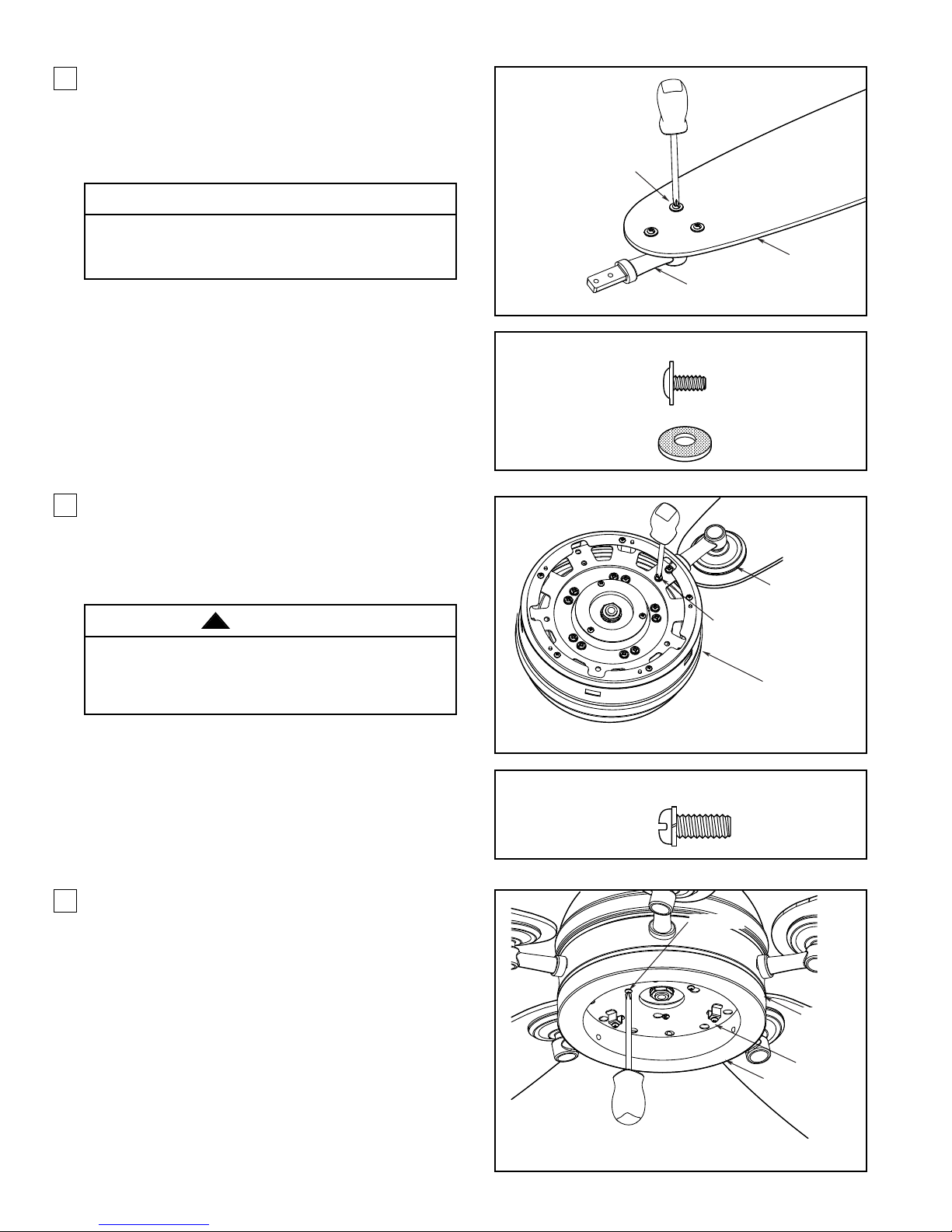
9
How to Assemble the Blades and Light Kit
Figure 1
Figure 2
Figure 3
1. Posit ion the blade over the blade holder with
threaded posts showing. Make sure the bottom
edge of the blade is fully seated against the blade
arm. With a Phillips screwdriver, tighten 3/16-24 x
7.5 mm washer head screws and fiber washers to
secure the blade to the blade arm (Figure 1).
2. Secure the blade holders to the motor support
using the 1/4-20 x 14 mm screws through the holes
located on the side of the motor support (Figure 2).
NOTE:
Periodically check blade holder hardware and
resecure if necessary.
3. Remove one of the three screws in the support
bracket at the bottom of the motor assembly.
Slightly loosen the remaining two screws.
Assemble the housing light kit assembly to the
support bracket using the two key slots in the
socket plate. Replace the third screw and securely
tighten all three screws (Figure 3).
Do not connect fan blades until the fan is completely
installed. Installing the fan with blades assembled
may result in damage to the fan blades.
CAUTION
To reduce the risk of personal injury, do not bend the
blade holders when installing, balancing the blades
or cleaning the fan. Do not insert foreign objects in
between the rotating blades.
WARNING
!
3/16-24 x 7.5mm WASHER
HEAD SCREW AND FIBER
WASHER (3 each per blade)
HARDWARE USED:
BLADE
BLADE HOLDER
3/16-24 x 7.5mm
WASHER HEAD
SCREWS
FIBER WASHER
HARDWARE USED:
1/4-20 x 14mm
SCREWS
x 16
x 16
BLADE HOLDER
1/2-20 x 14mm SCREWS
(2 per assembly)
MOTOR SUPPORT
x 6
SCREWS (3)
MOTOR
ASSEMBLY
SUPPORT
BRACKET
HOUSING LIGHT
KIT ASSEMBLY
Page 10
10
How to Assemble the Blades and Light Kit (continued)
Figure 4
Figure 5
Figure 6
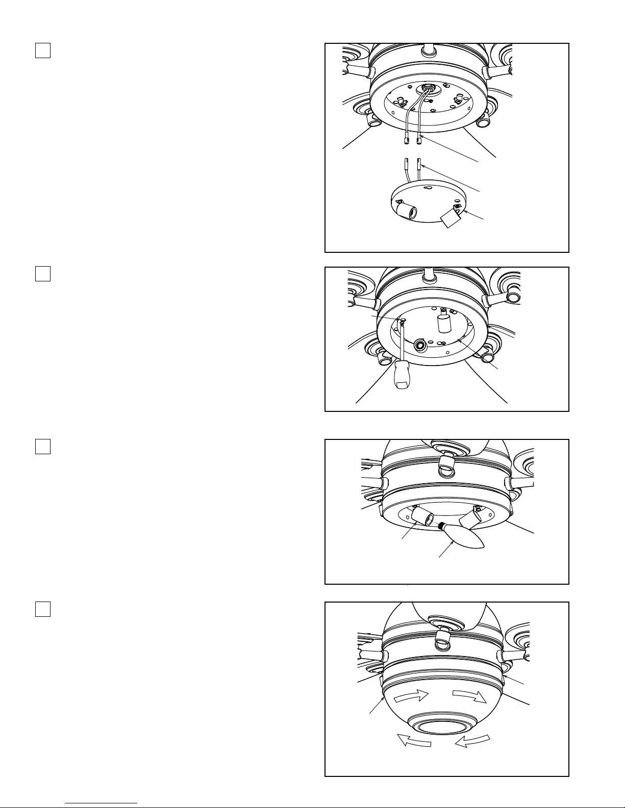
4. Connect the 2-pin connector from the light socket
plate to 2-pin connector from motor assembly
(Figure 4).
6. Insert light bulbs into sockets (Figure 6).
MOTOR ASSEMBLY
2-PIN CONNECTOR
LIGHT SOCKET 2-PIN
CONNECTOR
LIGHT SOCKET PLATE
5. Remove one of the three screws in the housing
light kit assembly. Slightly loosen the remaining
two screws. Assemble the light socket plate to the
housing light kit assembly using the two key slots.
Replace the third screw and securely tighten all
three screws (Figure 5).
SCREWS (3)
HOUSING LIGHT
KIT ASSEMBLY
7. Assemble the frosted glass to the adapter plate
assembly by twisting in a clockwise direction.
Do not over-tighten (Figure 7).
LIGHT SOCKET
60-WATT CANDELABRA LIGHT
BULBS (2)
LIGHT SOCKET
PLATE
FROSTED
GLASS
Figure 7
ADAPTER
PLATE
ASSEMBLY
Page 11
11
How to Operate Your Ceiling Fan
Figure 1
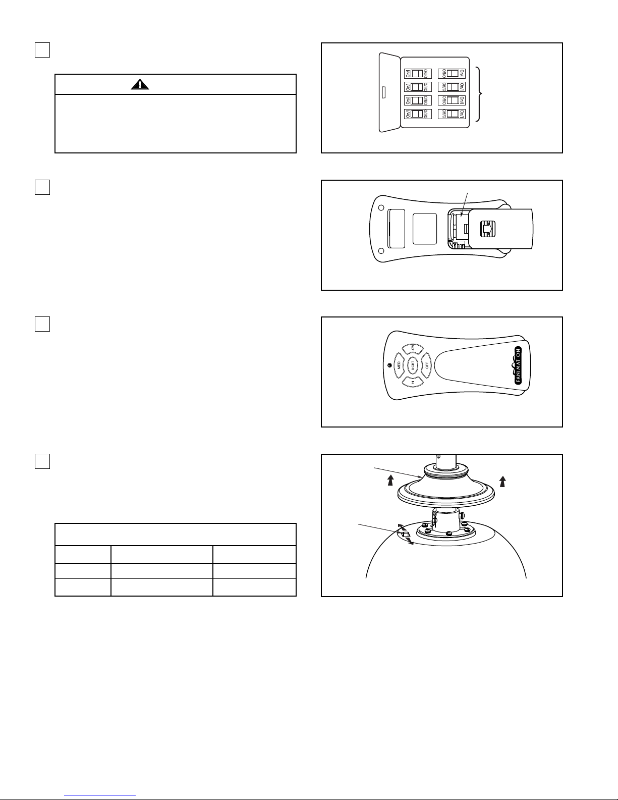
1. Restore electrical power to the outlet box by turning
the electricity on at the main fuse box (Figure 1).
Figure 2
2. To make fan operational, install 9-volt battery in
hand-held remote transmitter, (if not using for long
periods of time, remove battery to prevent damage
to transmitter). Store the remote away from
excessive heat or humidly (Figure 2).
Figure 3
3. The 5-button hand-held remote transmitter includes
five buttons for high, medium and low fan speeds
as well as fan off and light on/off. Infinite light levels
are available by holding the light on/off button
(Figure 3).
Figure 4
4. If airflow is desired in the opposite direction, turn
the fan off and wait for the blades to stop turning.
Slide the coupling cover up to expose the reverse
switch. Then slide the reverse switch on top of
motor assembly to the opposite position and turn
fan on again (Figure 4).
Check to see that all connections are tight, including
ground, and that no bare wire is visible at the wire
connectors, except for the ground wire. Do not
operate fan until the blades are in place. Noise and
fan damage could result.
WARNING
REMOTE
CONTROL
5-BUTTON
REMOTE
CONTROL
MAIN FUSE BOX
9V BATTERY
Reverse Switch Information
Season Rotation Direction Switch Position
Summer Counter-Clockwise Left
Winter Clockwise Right
COUPLING
COVER
REVERSE
SWITCH
Page 12

Maintenance
1. Periodic cleaning of your new ceiling fan is the only
maintenance that is needed. When cleaning, use
only a soft brush or lint free cloth to avoid
scratching the finish. Abrasive cleaning agents are
not required and should be avoided to prevent
damage to finish.
How to Clean Your Ceiling Fan Blades
Periodic light dusting of the blades is recommended.
A feather duster will work best.
CAUTION
Do not use water when cleaning your ceiling fan.
It could damage the motor or the finish and create
the possibility of electrical shock.
Avoid using water, cleansers, or harsh rags, which
can warp and ruin the finish.
12
Page 13
13
Trouble Shooting
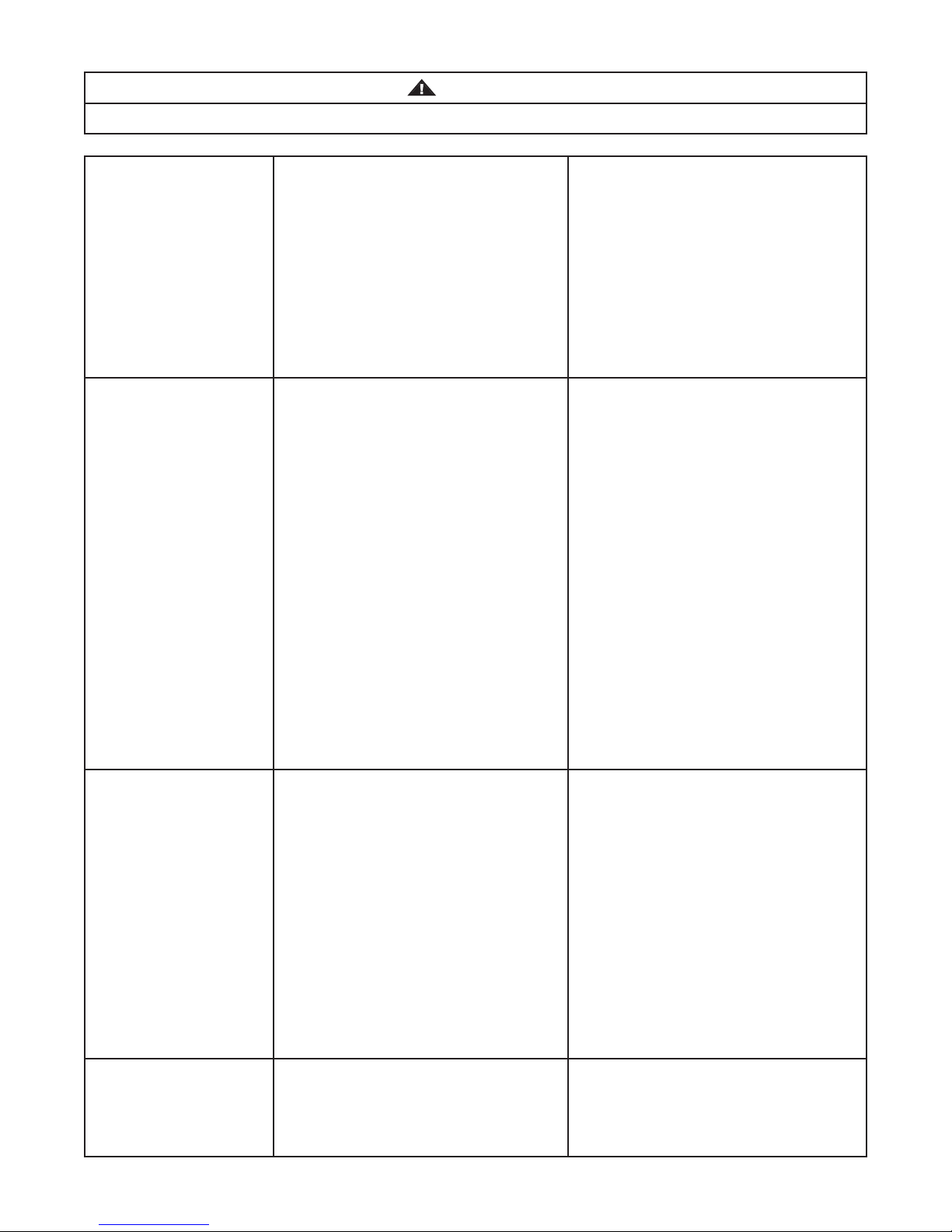
For your own safety turn off power at fuse box or circuit breaker before trouble shooting your fan.
WARNING
Trouble Probable Cause Suggested Remedy
1.FAN WILL
NOT START
1. Check main and branch circuit fuses
or circuit breakers.
2. Check line wire connections to fan
and switch wire connections in the
switch housings.
CAUTION: Make sure main power is
turned off !
3. Make sure reversing switch position is
all the way to one side.
4. Replace with fresh battery.
1. Fuse or circuit breaker blown.
2. Loose power line connections to the
fan, or loose switch wire connections
in the switch housing.
3. Reversing switch in neutral position.
4. Dead battery in remote control.
2.FAN SOUNDS NOISY
1. Attach blades to fan before operating.
2. Check to make sure all screws in
motor housing are snug (not overtight).
3. Check to make sure the screws which
attach the fan blade holders to the
motor flywheel are tight.
4. Check to make sure wire connectors
in switch housing are not rattling
against each other or against the
interior wall of the switch housing.
CAUTION: Make sure main power is
turned off !
5. Some fan motors are sensitive to
signals from solid-state variable
speed controls. Solid-state controls
are not recommended, choose an
alternative control method.
6. Tighten screws securely.
7. Tighten set screw securely.
1. Blades not attached to fan.
2. Loose screws in motor housing.
3. Screws securing fan blade holders to
motor flywheel are loose.
4. Wire connectors inside housing
rattling.
5. Motor noise caused by solid state
variable speed control.
6. Screws holding blades to blade
holders are loose.
7. Lower housing support set screw
loose.
3.FAN WOBBLES
EXCESSIVELY
1. Tighten both setscrews securely in
downrod support.
2. Tighten the setscrew in the downrod/
hanger ball assembly.
3. Check to be sure screws which attach
the fan blade holders to the flywheel
are tight.
4. Check to be sure the fan blade
holders seat firmly and uniformly to
the surface of the motor housing.
If holders are seated incorrectly,
loosen the screws and retighten.
5. Tighten the hanger bracket screws to
the outlet box, and secure outlet box.
6. Balance blades using balance kit
provided in hardware bag.
1. Setscrew in downrod support is loose.
2. Setscrew in downrod/hanger ball
assembly is loose.
3. Screws securing fan blade holders to
motor hub are loose.
4. Blade holders not seated properly.
5. Hanger bracket and/or ceiling outlet
box is not securely fastened.
6. Fan blades out of balance.
4.NOT ENOUGH AIR
MOVEMENT
1. If possible, consider using a longer
downrod. For example, use a 12”
downrod instead of the 4½” downrod
that comes with your fan.
Page 14
14
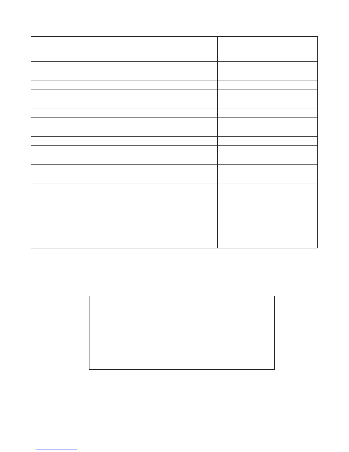
# traP noitpircseD # ecnerefeR
Parts List
Model No. FP8000**
1 Hanger Bracket Assembly w/Screws APGAC110RBL
**54-1CARDA)5.4( ylbmessA dornwoD - llaB2
**100008PyponaC3
4 Canopy Screw Cover Assembly APPAC1101**
**200008PAylbmessA revoC gnilpuoC rotoM
Fan Motor Assembly
5
**800008PA
AMA8000**
ylbmessA tiK thgiL gnisuoH
6
HW010008PAylbmessA tekcoS
7
06B21EPP)ttaW 06( bluB thgiL
8
9OP00008PssalG
9
**600008PA)5( teS mrA edalB
01
**700008PA)5( teS edalB
11
42ClortnoC etomeR dleH dnaH
21
54NACERtinU revieceR
31
**0008PFWDH:straP esooL ,ylbmessA gaB51
41
—)4( rotcennoC eriW—
— Washer Head Screw, 3/16-24 x 7.5 mm (16) —
—)61( ”61/3 ,rehsaW rebiF—
—)11( mm41 x 02-4/1 wercS daeH naP—
—revirdwercS daeH spillihP ”4—
—tiK ecnalaB—
HOW TO ORDER REPAIR PARTS
When ordering repair parts, always give the following information:
• Part Number
• Part Description
• Fan Model Number
Contact your retail store for repair parts.
Before discarding packaging material, be certain all parts have been removed.
** Insert FINISH CODES (Refer to fan model number located on downrod support)
Page 15
15
1
NOTE:
The illustration shown is not to scale or its actual configurations may vary.
13
2
3
4
5
11
6
12
14
15
7
8
9
10
Page 16

Copyright 2009 2009/06
10983 Bennett Parkway
Zionsville, IN 46077
Toll Free (888) 567-2055
FAX (866) 482-5215
Outside U.S. call (317) 733-4113
Visit Our Fanimation Website www.fanimation.com
 Loading...