

Fanimation Punkah FP720 Series, Punkah FP780 Series Owner's Manual

The Punkah
Motor and Fan Unit
®
Motor Assembly FP780_ _
Net Weight 17 lbs (7.71 kg)
Fan Unit FP720_ _
Net Weight 7 lbs (3.18 kg)
WARNING: Support Directly From Building Structure
OWNER’S MANUAL
READ AND SAVE THESE INSTRUCTIONS

Important Safety Instructions
WARNING: To avoid fire, shock and serious personal injury, follow these instructions.
1. Read your owner’s manual and safety information before installing your new fan. Review the accompanying assembly diagrams.
2. Before servicing or cleaning unit, switch power off at service panel and lock service panel disconnecting means to prevent power
from being switched on accidentally. When the service disconnecting means cannot be locked, securely fasten a warning device, such
as a tag, to the service panel.
3. Be careful of the fan and blades when cleaning, painting, or working near the fan. Always turn off the power to the ceiling fan before
servicing.
4. Do not insert anything into the fan blades while the fan is operating.
Additional Safety Instructions
1. To avoid possible shock, be sure electricity is turned off at the fuse box before wiring, and do not operate fan without blades.
2. All wiring and installation procedures must satisfy National Electrical Codes (ANSI/ NFPA 70-1999). Use the National Electrical Code
if Local Codes do not exist. The ceiling fan must be grounded as a precaution against possible electrical shock. Electrical installation
should be made or approved by a licensed electrician.
3. The fan base must be securely mounted and capable of reliably supporting at least 100 lbs. (fan and accessories not to exceed 35
lbs. or 16 kgs.). Outlet boxes are not acceptable for fan support. See page 4 of owner’s manual for support requirements. Consult a
qualified electrician if in doubt.
4. CAUTION: To reduce the risk of personal injury, mount the fan base to a ceiling joist or structural member using the hardware
provided with your fan.
WARNING: Support Directly from Building Structure.
5. The fan must be mounted at least 7 feet from the floor to prevent accidental contact with the fan blades.
6. Follow the recommended instructions for the proper method of wiring your ceiling fan. If you do not have adequate electrical
knowledge or experience, have your fan installed by licensed electrician.
7. Suitable for use with solid-state speed controls.
WARNING: TO REDUCE THE RISK OF SHOCK, THIS FAN MUST BE INSTALLED WITH AN ISOLATING WALL CONTROL/SWITCH.
WARNING: This product is designed to use only those parts supplied with this product and/or accessories designated specifically for
use with this product. Using parts and/or accessories not designated for use with this product could result in personal injury or property
damage.
WARNING: Do not insert foreign objects in between rotating fan blades.
LIMITED LIFETIME WARRANTY
Extends to the original purchaser of a Fanimation Fan
1. LIMITED LIFETIME MOTOR WARRANTY - If any part of your fan motor fails, due to a defect in materials or workmanship during
the lifetime of the original purchaser, Fanimation will provide the replacement part free of charge, when the defective fan is returned
to our national service center. Proof of purchase is required. Customer shall be responsible for all costs incurred in the removal or
reinstallation and shipping of the product for repairs or replacement.
2. ONE YEAR MOTOR LABOR WARRANTY - If your fan motor fails at any time within one year from the original purchase, due to
defects in materials or workmanship, labor to repair the motor will be provided free of charge at our national service center. Purchaser
will be responsible for labor charges after this one-year period. Customer shall be responsible for all costs incurred in the removal or
reinstallation and shipping of the product for repairs or replacement.
3. If any other part of your fan fails at any time within one year after original purchase, due to a defect in materials or workmanship, we
will repair, or replace, at our option, the defective part free of charge for parts and labor performed at our national service center.
4. Because of varying climate conditions, this warranty does not cover changes in the finish, including rusting, pitting, corroding,
tarnishing, or peeling.
5. This warranty is void and does not apply to damage from improper installation, neglect, accident, misuse, exposure to extremes of
heat or humidity, or as a result of any modification to the original product.
6. All costs of removal and reinstallation of the fan are the sole responsibility of the owner of the fan and not the store that sold the fan
or Fanimation.
7. Fanimation reserves the right to modify or discontinue any product at any time and may substitute any part under this warranty.
8. Under no circumstances may a fan be returned without prior authorization from Fanimation. The receipt of purchase must
accompany authorized returns and must be sent freight prepaid to Fanimation. The fan to be returned must be properly packed to
avoid damage in transit; Fanimation will not be responsible for any damage resulting from improper packaging.
9. It is understood that any repair or replacement is the exclusive remedy available from Fanimation. There is no other expressed or
implied warranty. Fanimation hereby disclaims any and all implied warranties, including, but not limited to those of merchantability and
fitness for a particular purpose to the extent permitted by law. Some states do not allow limitations on implied warranties. Fanimation
will not be liable for incidental, consequential, or special damages arising out of or in conjunction with product use or performance,
except as may otherwise be accorded by law. This warranty gives you special legal rights and you may also have other rights that vary
from state to state.
10. A certain amount of wobble is normal and should not be considered a problem or a defect.
Table of Contents
Unpacking Instructions. . . . . . . . . . . . . . . . . . . . . . . . . . . . . . . . . . . . . . . . . . . . . . . . . . . . . 3
Electrical and Structural Requirements . . . . . . . . . . . . . . . . . . . . . . . . . . . . . . . . . . . . . . . 4
Wiring and Control Options . . . . . . . . . . . . . . . . . . . . . . . . . . . . . . . . . . . . . . . . . . . . . . . . . 4
Hanging Options . . . . . . . . . . . . . . . . . . . . . . . . . . . . . . . . . . . . . . . . . . . . . . . . . . . . . . . . . . 5
Motor Mounting Bracket Hanging Options - Ceiling or Wall Mount . . . . . . . . . . . . . . . . . 6
Wiring Your Motor Assembly - Ceiling or Wall Mount . . . . . . . . . . . . . . . . . . . . . . . . . . . . 7
Mounting Head Assembly. . . . . . . . . . . . . . . . . . . . . . . . . . . . . . . . . . . . . . . . . . . . . . . . . . . 8
Assembling & Adjusting Connecting Rod Length . . . . . . . . . . . . . . . . . . . . . . . . . . . . . . . 9
Attaching Connecting Rods . . . . . . . . . . . . . . . . . . . . . . . . . . . . . . . . . . . . . . . . . . . . . . . . . 9
Installing the Blades . . . . . . . . . . . . . . . . . . . . . . . . . . . . . . . . . . . . . . . . . . . . . . . . . . . . . . 11
Final Connecting Rod Adjustments. . . . . . . . . . . . . . . . . . . . . . . . . . . . . . . . . . . . . . . . . . 11
Maintenance. . . . . . . . . . . . . . . . . . . . . . . . . . . . . . . . . . . . . . . . . . . . . . . . . . . . . . . . . . . . . 11
Parts List . . . . . . . . . . . . . . . . . . . . . . . . . . . . . . . . . . . . . . . . . . . . . . . . . . . . . . . . . . . . . . . 12
Exploded-View Drawing . . . . . . . . . . . . . . . . . . . . . . . . . . . . . . . . . . . . . . . . . . . . . . . . . . . 13
Trouble Shooting. . . . . . . . . . . . . . . . . . . . . . . . . . . . . . . . . . . . . . . . . . . . . . . . . . . . . . . . . 14
This Manual is Designed to Make it as Easy as Possible for You
to Assemble, Install, Operate, and Maintain Your Ceiling Fan
Tools Needed for Assembly Materials
• One Phillips head screwdriver
• One stepladder
• One ¼˝ blade screwdriver
▲
WARNING
Before assembling your ceiling fan, refer to section on
proper method of wiring your fan (page 7). If you feel you
do not have enough wiring knowledge or experience,
have your fan installed by a licensed electrician.
7
•
⁄16˝ Socket head wrench
• ⅛˝ Hex “L” wrench
• One wire stripper
Unpacking Instructions
For your convenience, check-off each step. As each step
is completed, place a check mark. This will ensure that all
steps have been completed and will be helpful in fi nding
your place should you be interrupted.
▲
WARNING
Do not install or use fan if any part is damaged or
missing. This product is designed to use only those
parts supplied with this product and/or any accessories
designated specifically for use with this product by
Fanimation. Substitution of parts or accessories not
designated for use with this product by Fanimation could
result in personal injury or property damage. Contact
your retail store for missing or damaged parts.
Check to see that you have received the following parts:
NOTE: If you are uncertain of part description, refer to
exploded view illustration. (Figure 18, page 13)
Wiring outlet box and box connectors must be of type required by local code. The minimum wire would be a 3-conductor (2-wire with ground) of the following size:
Wire Size A.W.G.Installed Wire Length
Up to 50 ft.
50 - 100 ft.
14
12
NOTE: Place the parts from the loose parts bags in a
small container to keep them from being lost. If any parts
are missing, contact your local retailer.
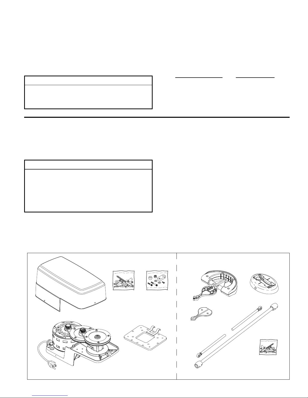
Motor Assembly Package
• Punkah™ Motor Assembly
• Motor Mounting Bracket
• Motor Cover
Motor Mounting Hardware Bag
contains:
– Lag Bolt, 2˝ long (2)
– Lag Bolt, 4˝ long (2)
– Hex Head Philips Screw (4)
– Lockwasher (4)
– Motor Cover Screw (3)
– Wire Nut (3)
Rod Mounting Hardware Bag
contains:
– Motor Link
– Hex Head Philips Screw
– Spacer
– Nylon Lock Nut
– Nylon Washer (2)
– Socket Head Screw, 1¾˝ long
– Socket Head Screw, 2¼˝ long
Fan Head Assembly Package
• Punkah™ Fan Head Assembly
– Base Mount
– Pivot Assembly
– Blade Cover
• Inner Rod Assembly (2)
• Outer Rod Assembly
Fan Head Hardware Bag contains:
– Lag Bolt, 2˝ long (2)
– Flat Washer (2)
– Socket Head Screw, 1½˝ long
– Socket Head Screw, 2˝ long
– Nylon Lock Nut
– Nylon Washer (2)
– Blade Cover Screw, 3/16˝-24 x 3/8˝ (2)
Motor Cover
Punkah® Motor
Assembly
Hardware Bag
for Motor Mounting
Motor Mounting
Hardware Bag
for Rod Mounting
Bracket
®
Fan
Base Mount
Hardware Bag
for Fan Head
Assembly
Blade Cover
Inner Rod
Assembly (2)
Punkah
Head Assembly
Pivot Assembly
Outer Rod
Assembly
3
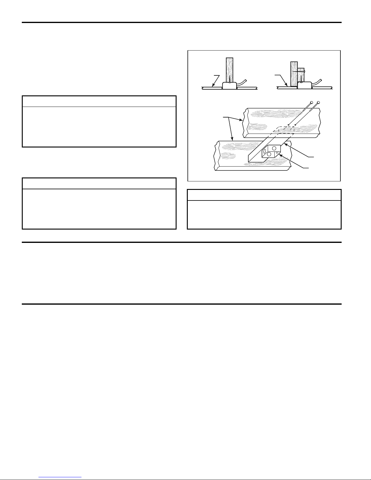
Electrical and Structural Requirements
Your new fan will require a grounded electrical supply line
of 120 volts AC, 60 Hz, 15 amp circuit. The outlet box must
be securely anchored and capable of withstanding a load
of at least 100 lbs. Figure 1 depicts different structural
confi gurations that may be used for mounting the outlet
box.
▲
WARNING
To reduce the risk of fire, electrical shock, or personal
injury, mount fan to outlet box marked acceptable for fan
support, and use screws supplied with outlet box. Most
outlet boxes commonly used for support of light fixtures
are not acceptable for fan support and may need to be
replaced. Consult a qualified electrician if in doubt.
Ceiling or
Wall
Ceiling
Joists
Ceiling or
Wall
If your fan is to replace an existing light fi xture, turn
electricity off at the main fuse box at this time and remove
the existing light fi xture.
▲
WARNING
Turning off wall switch is not sufficent. To avoid
possible electrical shock, be sure electricity is turned
off at the main fuse box before wiring. All wiring must
be in accordance with National and Local codes and the
ceiling fan must be properly grounded as a precaution
against possible electrical shock.
Wiring and Control Options
Please choose one of the following options and proceed
to the page as indicated.
1. Motor can be plugged into electrical outlet.
2˝ x 4˝
Outlet
Figure 1
▲
WARNING
To avoid fire or shock, follow all wiring instructions
carefully. Any electrical work not described in these
instructions should be done or approved by a licensed
electrician.
2. Motor can be wired directly to electrical service with a
standard light swich.
Box
4
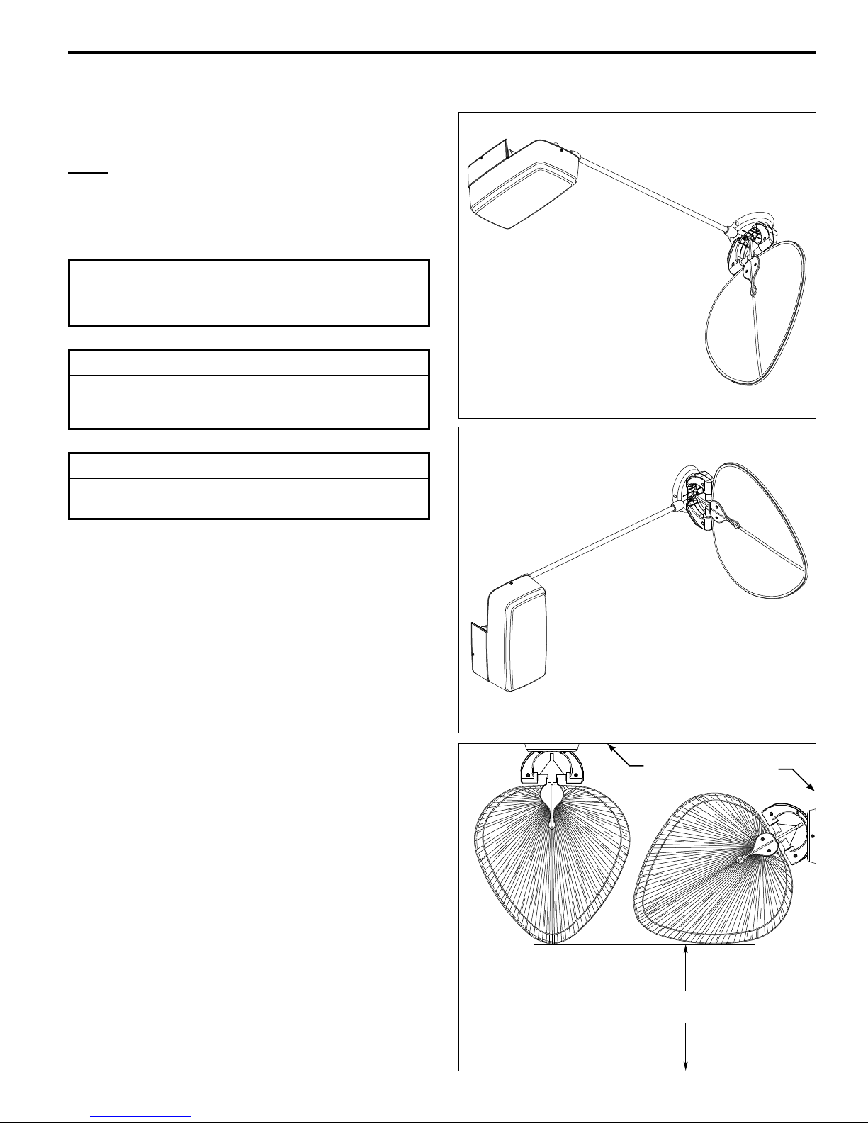
Hanging Options
Please choose one of two hanger options for your fan:
NOTE: Both The Motor Base And The Fan Head Base
MUST Be Mounted On The Same Surface (Plane).
Option 1 - Ceiling Mount (Figure 2a)
Option 2 - Wall Mount (Figure 2b)
INSTALLATION NOTE
Fan Motor can be mounted at either end of fi nal assembly
or in the middle.
CAUTION
Do not connect fan blades until the fan is completely
installed. Hanging fan with blades connected may result
in damage to the fan blades.
CAUTION
The fan must be hung with at least 7´ of clearance from
floor to blade(s) (Figure 3)
Figure 2a
Figure 2b
Ceiling
No
less than
7 ft
Figure 3
Wall
5
 Loading...