

Fanimation PL8018 Series Owner's Manual
The Pearson
Orbital Ceiling Fan
™
Model No. PL8018**
OWNER’S MANUAL
READ AND SAVE THESE INSTRUCTIONS
Net Weight 10.89 lb (4.49 kg)
Important Safety Instructions
WARNING: To avoid fire, shock and serious personal injury, follow these instructions.
1. Read your owner’s manual and safety information before installing your new fan. Review the accompanying assembly diagrams.
2. Before servicing or cleaning unit, switch power off at service panel and lock service panel disconnecting means to prevent power
from being switched on accidentally. When the service disconnecting means cannot be locked, securely fasten a warning device, such
as a tag, to the service panel.
3. Be careful of the fan and blades when cleaning, painting, or working near the fan. Always turn off the power to the ceiling fan before
servicing.
4. Do not insert anything into the fan blades while the fan is operating.
5. Do not operate reversing switch until fan blades have come to a complete stop.
6. The appliance is not intended for use by young children or infirm persons without supervision. Young children should be supervised to
ensure that they do not play with the appliance.
Additional Safety Instructions
1. To avoid possible shock, be sure electricity is turned off at the fuse box before wiring, and do not operate fan without blades.
2. All wiring and installation procedures must satisfy National Electrical Codes (ANSI/ NFPA 70-1999). Use the National Electrical Code
if Local Codes do not exist. The ceiling fan must be grounded as a precaution against possible electrical shock. Electrical installation
should be made or approved by a licensed electrician.
3. The fan base must be securely mounted and capable of reliably supporting at least 50 lbs. Outlet boxes are not acceptable for fan
support. See page 4 of owner’s manual for support requirements. Consult a qualified electrician if in doubt.
4. CAUTION: To reduce the risk of personal injury, mount the fan base to a ceiling joist or structural member using the hardware
provided with your fan.
WARNING: Support Directly from Building Structure.
5. The fan must be mounted with the fan blades at least 7 feet from the floor to prevent accidental contact with the fan blades.
6. Follow the recommended instructions for the proper method of wiring your ceiling fan. If you do not have adequate electrical
knowledge or experience, have your fan installed by a licensed electrician.
7. Suitable for use with solid-state speed controls.
8. This fan is to be used in damp locations.
9. For supply connections, if the conductor of a fan is identified as a grounded conductor, then it should be connected to a grounded
conductor power supply. If the conductor of a fan is identified as an ungrounded conductor, then it should be connected to an ungrounded
conductor power supply. If the conductor of a fan is identified for equipment grounding, then it should be connected to an
equipment grounding conductor.
WARNING: To reduce the risk of fire or electric shock, this fan should only be used with Fan Speed Control Part No. WASOF-02
GHUNGEAR INDUSTRIAL. CO., LTD
WARNING: TO REDUCE THE RISK OF SHOCK, THIS FAN MUST BE INSTALLED WITH AN ISOLATING WALL CONTROL/SWITCH.
WARNING: This product is designed to use only those parts supplied with this product and/or accessories designated specifically for
use with this product. Using parts and/or accessories not designated for use with this product could result in personal injury or property
damage.
WARNING: To reduce the risk of personal injury, do not bend the blade when installing the blades, or cleaning the fan. Do not insert
foreign objects in between rotating fan blades.
WARNING: All set screws must be checked and retightened where necessary before installation.
WARNING: (a) A lubricant should not be used on the single mounting screw; and (b) The pilot hole should be drilled no larger than the
minor diameter of the mounting screw threads, and at least 38mm (1½ inches) of the threaded part of the mounting screw should be
secured into a structural wood joist to provide secure mounting.
WARNING: Do not install or use fan if any part is damaged or missing.
LIMITED LIFETIME WARRANTY
Extends to the original purchaser of a Fanimation Fan
1. LIMITED LIFETIME MOTOR WARRANTY - If any part of your fan motor fails, due to a defect in materials or workmanship during
the lifetime of the original purchaser, Fanimation will provide the replacement part free of charge, when the defective fan is returned
to our national service center. Proof of purchase is required. Customer shall be responsible for all costs incurred in the removal or
reinstallation and shipping of the product for repairs or replacement.
2. ONE YEAR MOTOR LABOR WARRANTY - If your fan motor fails at any time within one year from the original purchase, due to
defects in materials or workmanship, labor to repair the motor will be provided free of charge at our national service center. Purchaser
will be responsible for labor charges after this one-year period. Customer shall be responsible for all costs incurred in the removal or
reinstallation and shipping of the product for repairs or replacement.
3. If any other part of your fan fails at any time within one year after original purchase, due to a defect in materials or workmanship, we
will repair, or replace, at our option, the defective part free of charge for parts and labor performed at our national service center.
4. Because of varying climate conditions, this warranty does not cover changes in the finish, including rusting, pitting, corroding,
tarnishing, or peeling.
5. This warranty is void and does not apply to damage from improper installation, neglect, accident, misuse, exposure to extremes of
heat or humidity, or as a result of any modification to the original product.
6. All costs of removal and reinstallation of the fan are the sole responsibility of the owner of the fan and not the store that sold the fan
or Fanimation.
7. Fanimation reserves the right to modify or discontinue any product at any time and may substitute any part under this warranty.
8. Under no circumstances may a fan be returned without prior authorization from Fanimation. The receipt of purchase must accompany authorized returns and must be sent freight prepaid to Fanimation. The fan to be returned must be properly packed to avoid
damage in transit; Fanimation will not be responsible for any damage resulting from improper packaging.
9. It is understood that any repair or replacement is the exclusive remedy available from Fanimation. There is no other expressed or
implied warranty. Fanimation hereby disclaims any and all implied warranties, including, but not limited to those of merchantability and
fitness for a particular purpose to the extent permitted by law. Some states do not allow limitations on implied warranties. Fanimation
will not be liable for incidental, consequential, or special damages arising out of or in conjunction with product use or performance,
except as may otherwise be accorded by law. This warranty gives you special legal rights and you may also have other rights that vary
from state to state.
10. A certain amount of wobble is normal and should not be considered a problem or a defect.
Unpacking Instructions . . . . . . . . . . . . . . . . . . . . . . . . . . . . . . . . . . 3
Energy Efficient Use of Ceiling Fans . . . . . . . . . . . . . . . . . . . . . . . . 4
Electrical and Structural Requirements
How to Assemble Your Ceiling Fan. . . . . . . . . . . . . . . . . . . . . . . . . 6
How to Hang Your Ceiling Fan. . . . . . . . . . . . . . . . . . . . . . . . . . . . . 7
How to Wire Your Ceiling Fan – Rotary Switch . . . . . . . . . . . . . . . 9
How to Wire Your Wall Control
. . . . . . . . . . . . . . . . . . . . . . . . . . . . . 9
. . . . . . . . . . . . . . . . . . . . . 4
Table of Contents
Installing the Canopy Housing . . . . . . . . . . . . . . . . . . . . . . . . . . . .
Operating Instructions – Rotary Switch . . . . . . . . . . . . . . . . . . . . .
Operating Instructions – Wall Control . . . . . . . . . . . . . . . . . . . . . . .
Maintenance . . . . . . . . . . . . . . . . . . . . . . . . . . . . . . . . . . . . . . . . . . .
Trouble Shooting. . . . . . . . . . . . . . . . . . . . . . . . . . . . . . . . . . . . . . . .
Parts List . . . . . . . . . . . . . . . . . . . . . . . . . . . . . . . . . . . . . . . . . . . . . . 12
Exploded-View Illustration . . . . . . . . . . . . . . . . . . . . . . . . . . . . . . . . 13
10
10
11
11
11
This manual is designed to make it as easy as possible for you
to assemble, install, operate, and maintain your ceiling fan
Tools Needed for Assembly Materials
• One Phillips head screwdriver
• One stepladder
• One ¼˝ blade screwdriver
7
•
⁄16˝ Socket head wrench
• One wire stripper
Wiring outlet box and box connectors must be of type required by local code. The minimum wire would be a 3-conductor (2-wire with ground) of the following size:
Wire Size A.W.G.Installed Wire Length
▲
WARNING
Before assembling your ceiling fan, refer to section on
proper method of wiring your fan (page 9). If you feel you
do not have enough wiring knowledge or experience,
have your fan installed by a licensed electrician.
Up to 50 ft.
50 - 100 ft.
NOTE: Place the parts from the loose parts bags in a
small container to keep them from being lost. If any parts
are missing, contact your local retailer.
14
12
Unpacking Instructions
For your convenience, check-off each step. As each step is completed, place a check mark. This will ensure that all
steps have been completed and will be helpful in fi nding your place should you be interrupted.
▲
WARNING
Do not install or use fan if any part is damaged or
missing. This product is designed to use only those
parts supplied with this product and/or any accessories
designated specifically for use with this product by
Fanimation. Substitution of parts or accessories not
designated for use with this product by Fanimation could
result in personal injury or property damage. Contact
your retail store for missing or damaged parts.
NOTE: If you are uncertain of part description, refer to
exploded view illustration. (Figure 1, page 13)
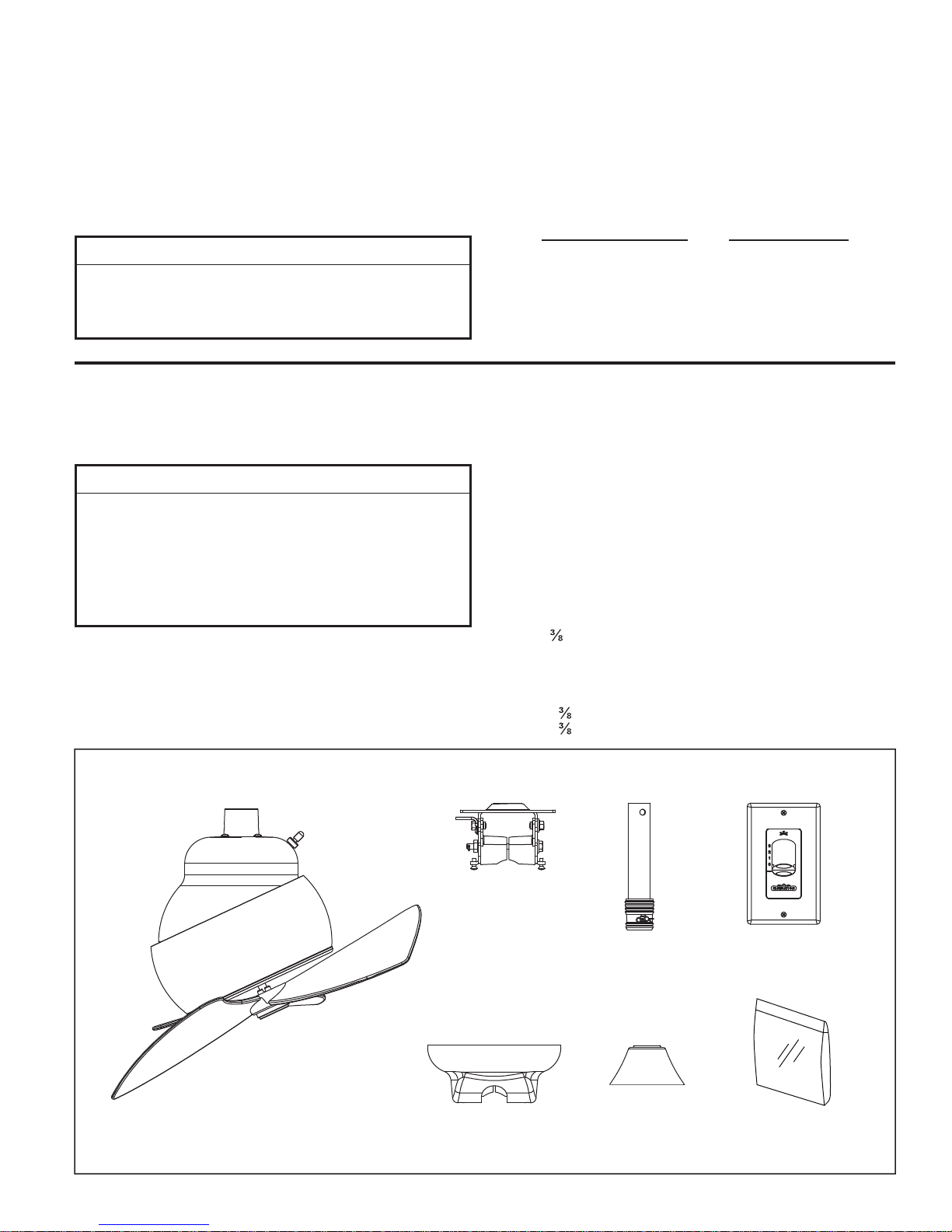
Check to see that you have received the following parts:
• Ceiling Fan assembly
• Downrod assembly
• Ceiling Canopy
• Hanger Bracket assembly
• Motor Coupling Cover
• Wall Control
• Hardware bag:
– Four wire connectors
– 7/16˝ wrench
– ˝ x 5˝ lag bolt with Flat Washer
– Phillips screwdriver, 1½˝
• Support Cable bag:
– Ceiling Support Cable
– Cable Clamp
– ˝ x 2˝ lag bolt
– ˝ fl at washer
Ceiling Fan
Assembly
Hanger
Bracket
Assembly
Ceiling Canopy
3
Downrod
Assembly
Motor Coupling
Cover
CWPL8018
Wall Control
Hardware Bag
Energy Efficient Use of Ceiling Fans
Ceiling fan performance and energy savings rely
heavily on the proper installation and use of the ceiling
fan. Here are a few tips to ensure efficient product
performance.
Choosing the Appropriate Mounting Location
Ceiling fans should be installed, or mounted, in the middle
of the room and at least 7 feet above the floor and 18
inches from the walls. If ceiling height allows, install the fan
8 - 9 feet above the floor for optimal airflow. Consult your
Fanimation Retailer for optional mounting accessories.
Turn Off When Not in the Room
Ceiling fans cool people, not rooms. If the room is
unoccupied, turn off the ceiling fan to save energy.
Electrical and Structural Requirements
Your new ceiling fan will require a grounded electrical
supply line of 120 volts AC, 60 HZ, 15 Amp Circuit.
Electrical code requires use of a fan-rated outlet box to
support the extra weight and motion associated with a
ceiling fan. A fan-rated box will be labeled as such and
typically supports up to a 70lb ceiling fan. Fan-Rated
Outlet Boxes vary in ratings and design. Ensure the
ratings of your ceiling fan outlet box meet the
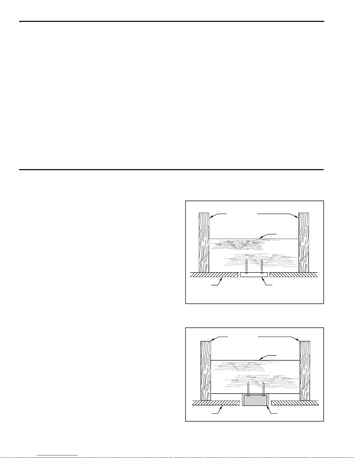
requirements for the ceiling fan being installed. Figure 1,
Figure 2 and Figure 3 depicts different structural
configurations that may be used for mounting the
outlet box.
Low profile usage diagram idea (Figure 1)
A 1⁄2-in.-deep pancake box is meant to be screwed to a
joist or block. It’s used if only one cable is coming into
the box. It is also available in a saddle-mount
configuration.
Using the Ceiling Fan Year Round
Summer Season: Use the ceiling fan in the counter-
clockwise direction. The airflow produced by the ceiling
fan creates a wind-chill effect, making you “feel” cooler.
Select a fan speed that provides a comfortable breeze,
lower speeds consume less energy.
Winter Season: Reverse the motor andoperate the ceiling
fan at low speed in the clockwise direction. This produces
a gentle updraft, which forces warm air near the ceiling
down into the occupied space.Remember to adjust your
thermostat when using your ceiling fan - additional energy
and dollar savings could be realized with this simple step!
CEILING JOIST
2" x 4"
CEILING
OUTLET BOX
Figure 1
Deeper profile usage diagram idea (Figure 2)
A 2-1⁄4-in.-deep box can be attached to blocking
between joists and is roomy enough to handle more
than one cable.
CEILING JOIST
2" x 4"
CEILING
Figure 2
OUTLET BOX
4
Electrical and Structural Requirements (Continued)
No blocking (Figure 3)
Paired with a deep box, this hanger is meant to span
between two joists and takes the place of wooden
blocking.
WARNING
To reduce the risk of fire, electrical shock, or
personal injury, mount fan to outlet box marked
acceptable for fan support of 15.88 kg (35 lbs) or less.
Use screws supplied with outlet box. Most outlet
boxes commonly used for support of light fixtures
are not acceptable for fan support and may need to
be replaced. Consult a qualifi e d electric i a n if
in doubt.
If your fan is to replace an existing light fixture, turn
electricity off at the main fuse box at this time and
remove the existing light fixture.
WARNING
Turning off wall switch is not sufficient. To avoid
possible electrical shock, be sure electricity is
turned off at the main fuse box before wiring. All
wiring must be in accordance with National and
Local codes and the ceiling fan must be properly
grounded as a precaution against possible electrical
shock.
CEILING JOIST
CEILING
OUTLET BOX
Figure 3
WARNING
To avoid fire or shock, follow all wiring instructions
carefully. Any electrical work not described in these
in structions should be done or approv ed by a
licensed electrician.
5
How to Assemble Your Ceiling Fan
CAUTION
To prevent damage to housing and/or blade, leave the
Ceiling Fan Assembly in its original packing during
installation of down rod, motor coupling cover and
ceiling canopy.
NOTE: Do not set Ceiling Fan Assembly on fl oor or hard
surface. Prior to assembly, set aside and save the hardware
bag(s) packed in the packing.
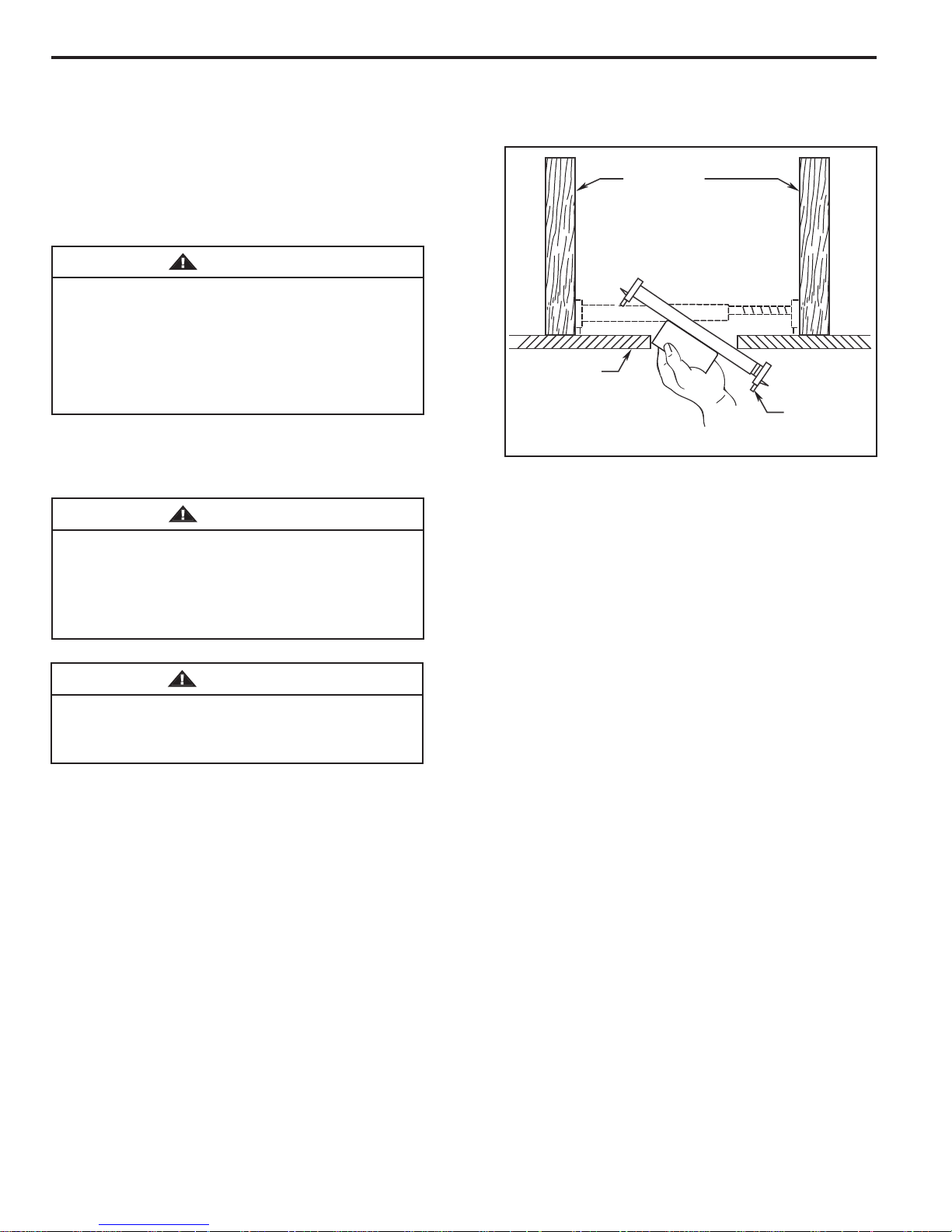
NOTE: If using a downrod other than what is supplied
with the fan, you must remove rubber sleeve from 6˝
downrod and put on new downrod.
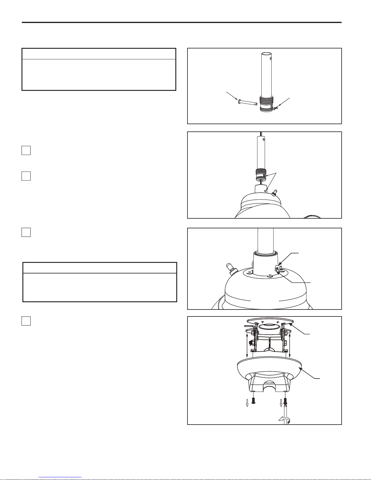
1. Remove the hairpin clip and clevis pin from the
bottom of the downrod. Retain the pin and clip for
reinstallation in Step 3. (Figure 1)
2. The fan comes with black, white and green 80˝ wires
and a support cable. Separate and untwist the wires.
Route the wires and support cable through the
downrod with rubber sleeve. Be sure to line up the
holes while pushing the downrod with rubber sleeve
into the downrod support. (Figure 2)
Clevis Pin
Hairpin
Clip
Figure 1
Line up the
holes for clevis
pin installation
Figure 2
3. Install the clevis pin through the holes in the downrod
support and holes in the downrod. Secure clevis pin
with hairpin clip. Pull up on the downrod to assure the
clevis pin is properly installed. (Figure 3)
▲
WARNING
It is critical that the clevis pin in the downrod support
is properly installed. Failure to verify that the pin and
hairpin clip are properly installed could result in the fan
falling.
4. Separate the hanger bracket from the ceiling canopy
by removing two screws. Retain the two screws for later.
(Figure 4)
Clevis Pin
Hairpin Clip
Figure 3
Hanger
Bracket
Canopy
Figure 4
6
How to Assemble Your Ceiling Fan (continued)
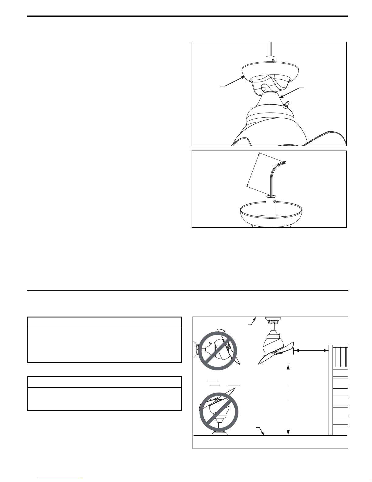
5. Slide the motor coupling cover down until it touches
the top of the motor and assemble ceiling canopy as
shown. (Figure 5)
6. Before installing fan, cut off excess lead wire
approximately 6-9 inches above top of downrod. Strip back
back insulation ½” from end of each wire. (Figure 6)
7. You have now completed the assembly of your new
ceiling fan. You can now proceed with the hanging and
the electrical wiring of your fan.
Ceiling
Canopy
o
6 t
9 i
.
n
Motor
Coupling
Cover
Figure 5
Figure 6
How to Hang Your Ceiling Fan
▲
WARNING
To avoid possible electrical shock, be sure electricity is
turned off at the main fuse box before hanging.
NOTE: If you are not sure if the outlet box is grounded,
contact a licensed electrician for advice, as it must be
grounded for safe operation.
▲
WARNING
The fan must be hung with at least 7´ of clearance from
floor to blade and MUST ONLY be hung in a vertical
downward position from ceiling. (Figure 1)
WARNING:
Do NOT Mount Fan
On Wall Or Floor!
7
Ceiling
2 ft min.
from
staircase
or wall
No
less than
7 ft
Floor
Figure 1
How to Hang Your Ceiling Fan (continued)
CAUTION
To Reduce the Risk of Personal Injury, this Product Must
be Secured as Described in the Manual.
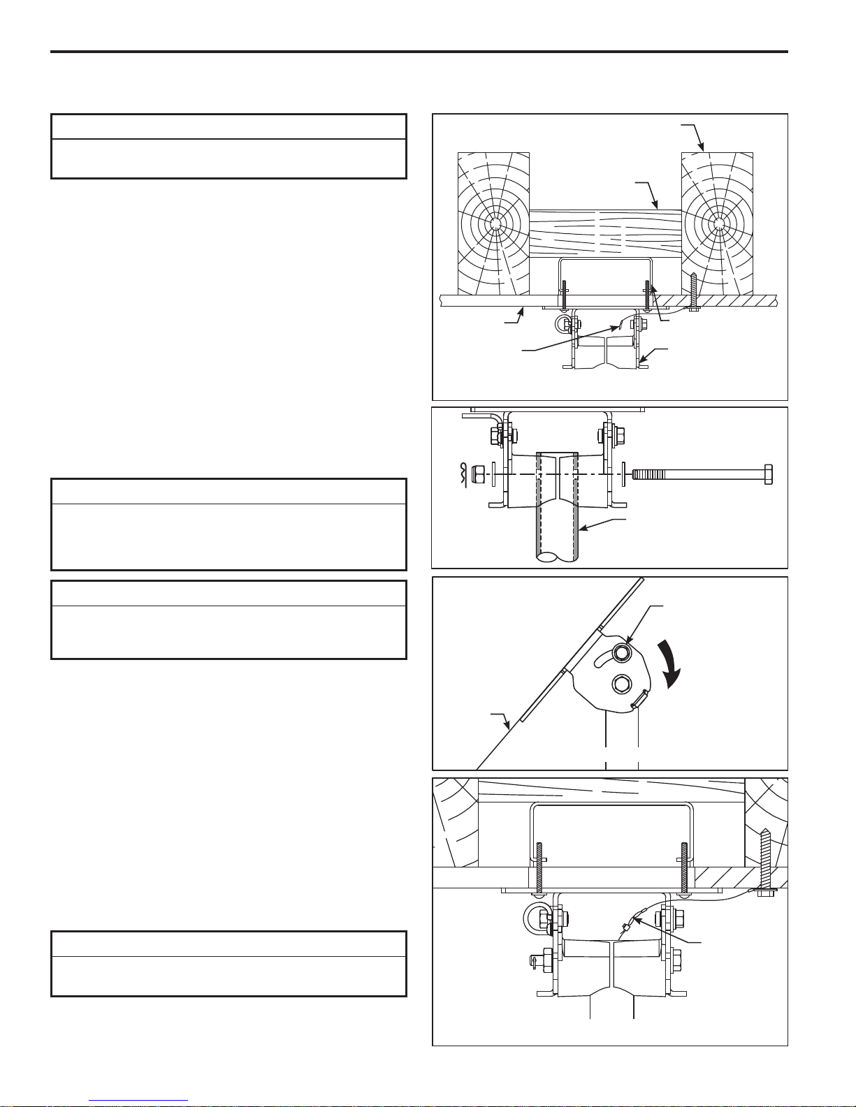
1. Attaching Ceiling Support Cable (Figure 2): Drill
¼˝ pilot hole through into the ceiling joist or structural
member. Securely attach the ceiling support cable with
3
⁄8˝ x 2˝ lag bolt and fl at washer.
NOTE: Ceiling support cable must be directly secured to
ceiling joist or structural member between fl at washer and
junction box with 2˝ lag bolt (Figure 2).
2.
Hanger Bracket Attachment:
Securely attach the hanger bracket to the outlet box using
the outlet box screws and washers supplied with the outlet
box (Figure 2).
3. Assemble and secure the assembled fan with hexhead bolt, two lockwashers, nylon locknut and clevis pin.
(Figure 3)
▲
WARNING
It is critical that the clevis pin and lock nut in the hanger
bracket/downrod area is properly installed. Failure to
verify that the nut and hairpin clip are properly installed
could result in the fan falling.
Ceiling
Ceiling
Support
Cable
Ceiling Joist
Wood Member
(2” x 4” Approx.)
Junction
Box
Hanger Bracket
Figure 2
Downrod
(Assembled Fan)
Figure 3
INSTALLATION NOTE
The hanger bracket angle adjustment MUST ONLY be
used to orientate the downrod in a vertical downward
position.
4. (Optional)
Loosen two nuts located on both sides of the hanger
bracket to orientate the downrod in the vertical position.
5. Make sure the electrical supply wires, including the
hanger bracket grounding wire and safety cable are
pulled through the downrod, between the hanger bracket
and the junction box so that electrical connections can be
made later.
6. Attach the safety cable to ceiling support cable. Slide
cable clamp onto safety cable (from fan). Place the end
of cable through the loop of ceiling support cable. Pull as
much cable through loop as possible. Feed end of cable
into clamp hole and fi rmly tighten screw (Figure 5). Cut
off excess safety cable.
To avoid possible shock, do not pinch wires between the
downrod and the hanger bracket.
Sloped Ceiling Installation (Figure 4)
▲
WARNING
:
Loosen Nuts on
both sides of the
Hanger Bracket
Sloped
Ceiling
Figure 4
Attach
Safety Cable
to Ceiling
Support
Cable
NOTE: Supply wires and
fan wires omitted for clarity
8
Figure 5
How to Wire Your Ceiling Fan – Rotary Switch
If you feel that you do not have enough electrical wiring
knowledge or experience, have your fan installed by a
licensed electrician.
▲
WARNING
To avoid possible electrical shock, be sure electricity is
turned off at the main fuse box before wiring.
NOTE: If you are not sure if the outlet box is grounded,
contact a licensed electrician for advice, as it must be
grounded for safe operation.
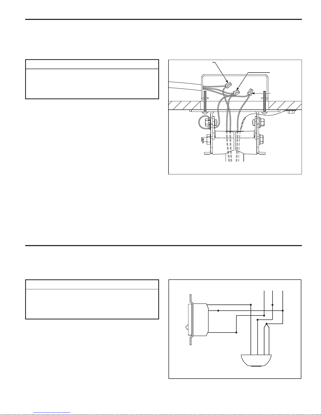
1. Run the black, white and green wires through the
wiring hole in the side of the hanger bracket to allow for
electrical connections.
2. Connect the green grounding wire from the fan and
hanger bracket to the grounding wire from the outlet box
(this may be a bare wire or a wire with green insulation).
Securely connect these wires with wire connector
supplied with your fan.
3. Securely connect the white wire from the fan motor
to the white supply (neutral) wire using wire connector
supplied (Figure 1).
4. Securely connect the black fan motor wire to the black
supply wire using wire connector supplied (Figure 1).
NOTE: If fan or supply wires are different colors than indicated,
have this unit installed by a qualifi ed electrician.
120 VAC
Supply
(User
Supplied)
White
(Neutral)
Green Wire
(Ground)
(To/From
hanger
bracket
and fan)
Black Wire
(Hot)
Figure 1
5. After connections have been made, turn leads upward
and carefully push leads into the outlet box, with the white
and green leads to one side of the box and the black
leads towards the other side.
6. The wires should be spread apart with the grounded
conductor and the equipment-grounding conductor on
one side of the outlet box and the ungrounded conductor
on the other side of the outlet box.
How to Wire Your Wall Control
If you feel that you do not have enough electrical wiring knowledge or experience, have your fan installed by a
licensed electrician.
▲
WARNING
To avoid possible electrical shock, be sure electricity is
turned off at the main fuse box before wiring.
NOTE: If you are not sure if the outlet box is grounded,
contact a licensed electrician for advice, as it must be
grounded for safe operation.
1. Installing Wall Control (Figures 1 & 2):
• With electrical power still disconnected, remove the
existing wall plate and switch.
• Make wiring connections with wire nuts as shown in
Figure 1.
– One black wire from wall control unit to black
(hot supply).
– One black wire from wall control unit to black wire
leading to ceiling outlet box.
– One green wire from wall control unit to ground wire
leading to ceiling outlet box.
BLK TO FAN
GRN
TO GROUND
BLK
TO HOT
Figure 1
120 VAC SUPPLY
(User Supplied)
BLK
WH-TO MOTOR
BLK-TO MOTOR
GRN from hanger ball
WH
GRN
GRN from bracket
9
 Loading...