

Page 1
C25 Wireless Wall Control
SPECIFICATION and INSTRUCTION SHEET
DESCRIPTION: One Ceiling Fan & Light, 3 Speed Wireless Wall Control
FAN MODEL USED: May be used in conjunction with TR24** Remote Control
See Catalog or visit our website www.fanimation.com for more information
How to Set and Operate Your C25 Wireless Wall Control
If you feel that you do not have enough electrical wiring
knowledge or experience, have your fan installed by a
licensed electrician.
WARNING
To avoid possible electrical shock, be sure electricity is
turned off at the main fuse box before wiring.
NOTE: If you are not sure if the outlet box is grounded,
contact a licensed electrician for advice, as it must be
grounded for safe operation.
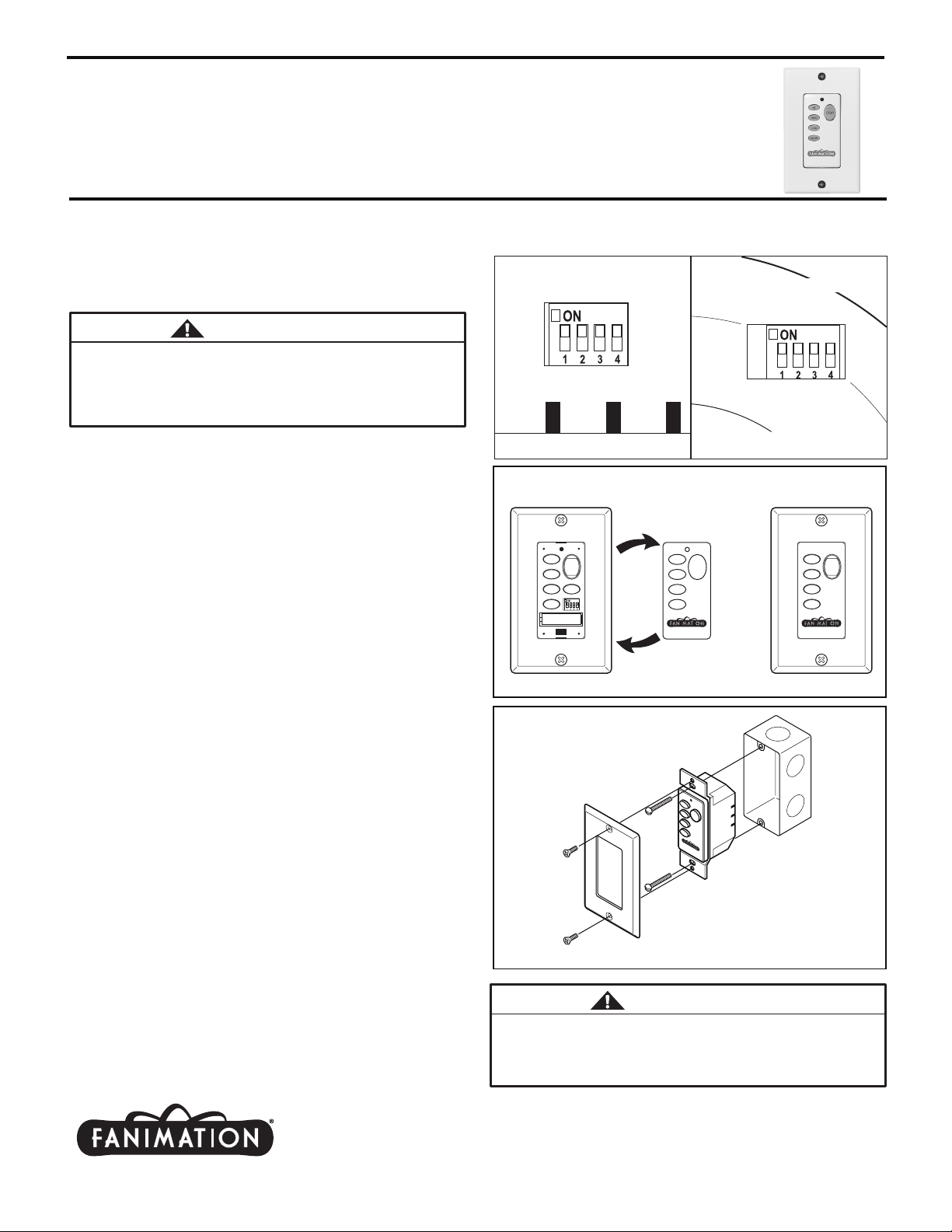
1. Setting the Code: The remote unit has 16 different
code combinations. It may be necessary to test a couple
frequency code settings to improve signal reception and/or
eliminate interference from other remote control household
items. Multiple fans should have different code settings to
allow independent fan control. To set the code, perform
these steps.
2. Receiver: Slide code switches to your choice of up or
down position. Factory setting is all up. Do not use this
position. With a small screwdriver or ball point pen slide
firmly up or down (Figure 1b).
3. Transmitter: Remove the cover plate. Slide code
Install the battery. Re-install the cover plate (Figure 1a)
(Figure 2).
Wall Transmitter Unit Detail
(located on side of Wall Control)
Wall Transmitter Unit Detail
(located on front of Wall Control
HI
LIGHT
MED
LOW
FAN OFF
_
+ AA Battery
.reviecer ruoy no tes sa snoitisop emas eht ot sehctiws
Receiver Unit Detail
behind the cover plate)
Figure 2
Figure 1bFigure 1a
HI
LIGHT
MED
LOW
FAN OFF
4. Installing Wireless Wall Transmitter (Figure 3):
• Remove the existing wall plate and switch.
• Be sure to complete the electrical circuit within the junction
box by-passing wall control. Connect black to black, white
to white, green to green. Carefully push wires into the
outlet box.
• Attach wall control unit to outlet box using the two 6-32
screws provided.
• Attach wall plate to the switch control front using the two
small screws provided.
• Restore electrical power.
NOTE: In case of weak reception, replace battery inside
wall control.
5. Operating & Using Wall Transmitter:
• HI Push Button – high fan speed
• MED Push Button – medium fan speed
• LOW Push Button – low fan speed
• OFF Push Button – fan off
• Light Push Button – toggles on/off and brightness control
for optional light arms
10983 Bennett Parkway
Zionsville, IN 46077
(888) 567-2055 • FAX (866) 482-5215
Outside U.S. call (317) 733-4113
Visit Our Website @ www.fanimation.com
H
I
M
L
E
I
G
D
H
T
L
O
W
F
A
N
O
F
F
NOTE: Supply wires and fan wires
omitted for clarity.
Figure 3
WARNING
Check to see that all light arm connections are tight, and
that no bare wire is visible at the wire connectors. Do not
operate fan until the side covers are in place. Noise and
fan damage could result.
Copyright 2010 Fanimation
2013/02
 Loading...