

Page 1
Ceiling Fan LK122 Installation Instructions
WARNING
Turning off wall switch is not sufficent. To avoid
possible electrical shock, be sure electricity is turned off
at the main fuse box before removing, installing, or
servicing the light fixture.
CAUTION
All fitters/light kits must only be used with ceiling fans.
Do NOT install as a lighting fixture attached to building
structure!
NOTE: These instructions are intended to cover various fan models
(Americana, Brewmaster [on motor], Islander, Louvre, Palisade,
Sandella, Treventi & Tropicana).
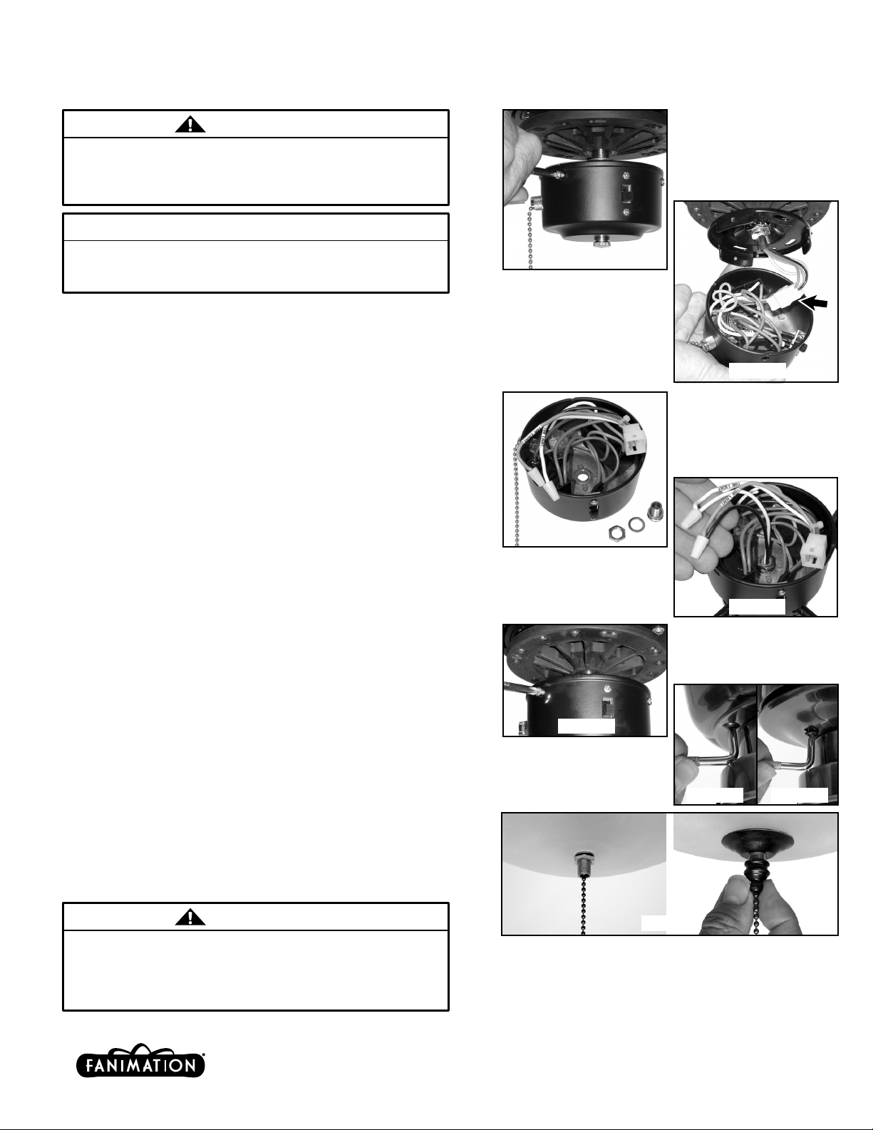
Figure 1
1. Remove the switch housing from the fan by unscrewing the
housing screws and unplugging the connector (Figures 1 & 2).
2. Remove the threaded plug, lockwasher, and nut from the
center of this cover by unscrewing it. You may discard or keep
them for future use (Figure 3).
3. Attach the switch housing to the fitter/light kit by feeding the
wires (black & white) through the hole of the switch housing,
place lockwasher over the fitter/light kit leads & nipple and
fasten the fitter/light kit with the nut provided onto the nipple.
Be sure it is tight enough to prevent fitter/light kit from vibrating
loose (Figure 4).
4. Locate two single wires in switch housing. White (gray on
some models) and blue (red on some models) labeled "FOR
LIGHT" (Figure 3).
5. Connect them to the fitter/light kit wires (Figure 4);
- White (gray) to white
- Blue (red) to black
6. Carefully reconnect the connector and push all wires back into
switch housing of fan. Then replace cover with original screws.
(Figure 5-various fan models) (Figure 6-Sandella model)
(Figure 7-Treventi model)
Figure 2
Figure 3
Figure 4
Figure 5
7. Install appropriate bulbs (not provided). Install glass bowl
(while supporting the bowl) by attaching the rubber washer and
the hex nut. Install the bowl cap and the final nut onto the
center of the light kit (Figure 8).
8. Restore the power and your light kit is ready for operation.
WARNING
Check to see that all connections are tight. To avoid
possible electrical shock, make sure that the electrical
wires are completely inside the switch housing and not
pinched between the switch cap base and switch
housing.
10983 Bennett Parkway
Zionsville, IN 46077
(888) 567-2055 • FAX (866) 482-5215
Visit Our Website @ fanimation.com
Figure 6 Figure 7
Figure 8
2004/01
 Loading...