

Page 1
WR501WH Wall Control
SPECIFICATION and INSTRUCTION SHEET
DESCRIPTION: 3-speed ceiling fan control with light dimmer switch and canopy receiver.
ELECTRICAL SPECS: 120V, 60Hz Ceiling Fan
FAN MODELS USED: most Fanimation fans - see catalog or visit our website, fanimation.com for
more information
How to Wire and Operate Your Wall Control
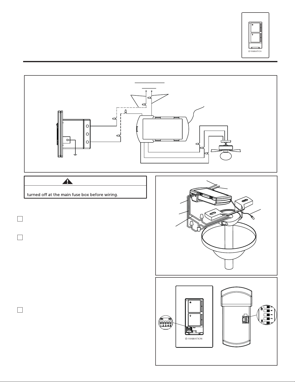
AC120V 60HZ
INPUT
BLACK (AC IN L)
BLACK
BLACK (AC IN L)
WHITE (AC IN N)
BLACK (AC IN L)
BLACK (TO MOTOR L)
GROUND WIRE
GREEN / YELLOW
BLACK
Figure 1
WARNING
To avoid possible electrical shock, be sure electricity is
NOTE: If fan or supply wires are different colors than
indicated, have this unit installed by a qualified electrician.
1. If fan and/or light kit are controlled by a pull chain, fan
must be set to high and light kit must be switched on.
2.
Dip Switch Set Up (Figure 3)
NOTE: The remote unit has 32 different code
combinations. To prevent possible interference from or
to other remote units, simply change the combination
code in the remote and receiver.
NOTE: Factory setting is all up. Do not use this position.
• To set the code on receiver unit, slide dip switches to
the same positions as set on the remote.
• To set the remote code with a small screwdriver or
ball point pen (neither included), slide dip switches
firmly up or down to same as receiver unit.
Install Receiver in the Hanger Bracket:
3.
• Connect wires using connectors as shown in Figure 1.
• Position all connected wires and receiver antenna to
allow installation of ceiling canopy. (Figure 2)
• Using canopy screws threaded into the hanger bracket
reinstall ceiling canopy.
• Restore electrical power
BLUE(FOR LIGHT)
BLACK(TO MOTOR L)
WHITE(TO MOTOR N)
WHITE
(TO MOTOR N)
BLACK
(TO MOTOR L)
BLUE
(FOR LIGHT)
Dip Switch
WHITE
(AC IN N )
BLUE
BLACK
WHITE
BLACK
(AC IN L)
BLACK
(ANTENNA)
Figure 2
Dip Switch
Figure 3
Page 2
4.
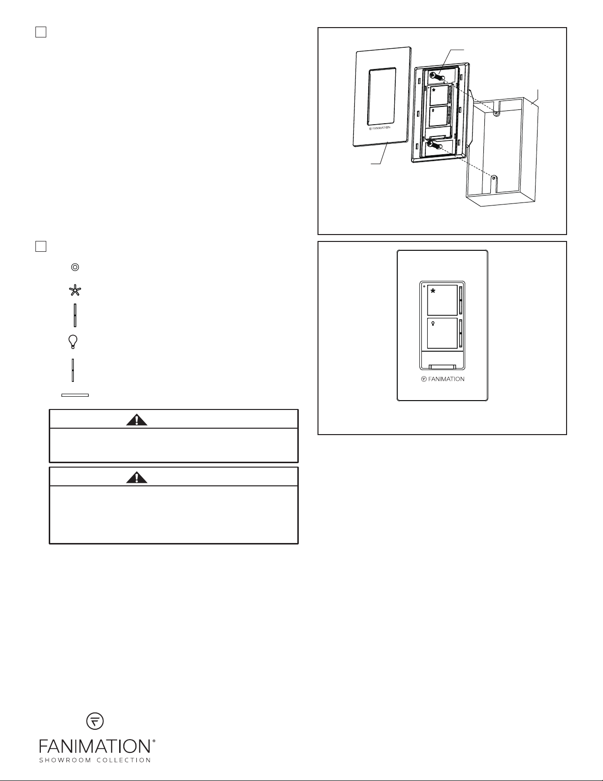
Attach wall control unit to outlet box using the two
screws provided. Then, attach face plate to the wall
control. (Figure 4)
• Restore electrical power.
5. Operating Wall Control: (Figure 5)
- Indicator LED light
- Fan off
- Fan speed control: Turns on fan and turns
speed up or down.
Face Plate
NOTE: Supply wires and fan wires
omitted for clarity.
Screw
Outlet Box
Figure 4
- Turns light ON/OFF.
- Light Dimmer: Up or down to brighten or dim
light.
- Pull out to turn all power off.
WARNING
To avoid possible fire or shock, make sure that the
electrical wires are completely inside the outlet box and
not pinched between the wall plate and the wall.
WARNING
Check to see that all connections are tight, including
ground, and that no bare wire is visible at the wire
connectors, except for the ground wire. Do not operate
fan unless blades are in place. Noise and fan damage
could result.
Figure 5
10983 Bennett Parkway
Zionsville, IN 46077
(888) 567-2055 • FAX (866) 482-5215
Outside U.S. call (317) 733-4113
WWW.FANIMATION.COM
Copyright 2018 Fanimation
2018/12 V.01
 Loading...