

Fanimation Islander, islander FP320**1-220 Owner's Manual
The Islander
Ceiling Fan
®
Standard & Damp Location Models
Model No. FP320**1
OWNER’S MANUAL
READ AND SAVE THESE INSTRUCTIONS
Damp Location Model; Top of fan is marked, “Suitable For Use In Damp Locations”
Net Weight 19 lbs.
Important Safety Instructions
WARNING: To avoid fire, shock and serious personal injury, follow these instructions.
1. Read your owner’s manual and safety information before installing your new fan. Review the accompanying assembly diagrams.
2. Before servicing or cleaning unit, switch power off at service panel and lock service panel disconnecting means to prevent power
from being switched on accidentally. When the service disconnecting means cannot be locked, securely fasten a warning device, such
as a tag, to the service panel.
3. Be careful of the fan and blades when cleaning, painting, or working near the fan. Always turn off the power to the ceiling fan before
servicing.
4. Do not insert anything into the fan blades while the fan is operating.
5. Do not operate reversing switch until fan blades have come to a complete stop.
Additional Safety Instructions
1. To avoid possible shock, be sure electricity is turned off at the fuse box before wiring, and do not operate fan without blades.
2. All wiring and installation procedures must satisfy National Electrical Codes (ANSI/ NFPA 70-1999). Use the National Electrical
Code if Local Codes do not exist. The ceiling fan must be grounded as a precaution against possible electrical shock. Electrical
installation should be made or approved by a licensed electrician.
3. The fan base must be securely mounted and capable of reliably supporting at least 100 lbs. (fan and accessories not to exceed 35
lbs. or 16 kgs.). Outlet boxes are not acceptable for fan support. See page 5 of owner’s manual for support requirements. Consult a
qualified electrician if in doubt.
4. CAUTION: To reduce the risk of personal injury, mount the fan base to a ceiling joist or structural member using the hardware
provided with your fan.
WARNING: Support Directly from Building Structure.
5. The fan must be mounted with the fan blades at least 7 feet from the floor to prevent accidental contact with the fan blades.
6. Follow the recommended instructions for the proper method of wiring your ceiling fan. If you do not have adequate electrical
knowledge or experience, have your fan installed by licensed electrician.
7. Suitable for use with solid-state speed controls.
WARNING: To reduce the risk of fire or electric shock, this fan should only be used with Fan Speed Control Part No. UC7051R,
manufactured by Rhine Electronic Co., Ltd.
WARNING: TO REDUCE THE RISK OF SHOCK, THIS FAN MUST BE INSTALLED WITH AN ISOLATING WALL CONTROL/SWITCH.
WARNING: This product is designed to use only those parts supplied with this product and/or accessories designated specifically for
use with this product. Using parts and/or accessories not designated for use with this product could result in personal injury or property
damage.*
WARNING: To reduce the risk of personal injury, do not bend the blade bracket (flange or blade holder) when installing the brackets,
balancing the blades, or cleaning the fan. Do not insert foreign objects in between rotating fan blades.
.
LIMITED LIFETIME WARRANTY
Extends to the original purchaser of a Fanimation Fan
1. LIMITED LIFETIME MOTOR WARRANTY - If any part of your fan motor fails, due to a defect in materials or workmanship during
the lifetime of the original purchaser, Fanimation will provide the replacement part free of charge, when the defective fan is returned
to our national service center. Proof of purchase is required. Customer shall be responsible for all costs incurred in the removal or
reinstallation and shipping of the product for repairs or replacement.
2. ONE YEAR MOTOR LABOR WARRANTY - If your fan motor fails at any time within one year from the original purchase, due to
defects in materials or workmanship, labor to repair the motor will be provided free of charge at our national service center. Purchaser
will be responsible for labor charges after this one-year period. Customer shall be responsible for all costs incurred in the removal or
reinstallation and shipping of the product for repairs or replacement.
3. If any other part of your fan fails at any time within one year after original purchase, due to a defect in materials or workmanship, we
will repair, or replace, at our option, the defective part free of charge for parts and labor performed at our national service center.
4. Because of varying climate conditions, this warranty does not cover changes in the finish, including rusting, pitting, corroding,
tarnishing, or peeling.
5. This warranty is void and does not apply to damage from improper installation, neglect, accident, misuse, exposure to extremes of
heat or humidity, or as a result of any modification to the original product.
6. All costs of removal and reinstallation of the fan are the sole responsibility of the owner of the fan and not the store that sold the fan
or Fanimation.
7. Fanimation reserves the right to modify or discontinue any product at any time and may substitute any part under this warranty.
8. Under no circumstances may a fan be returned without prior authorization from Fanimation. The receipt of purchase must accompany authorized returns and must be sent freight prepaid to Fanimation. The fan to be returned must be properly packed to avoid
damage in transit; Fanimation will not be responsible for any damage resulting from improper packaging.
9. It is understood that any repair or replacement is the exclusive remedy available from Fanimation. There is no other expressed or
implied warranty. Fanimation hereby disclaims any and all implied warranties, including, but not limited to those of merchantability and
fitness for a particular purpose to the extent permitted by law. Some states do not allow limitations on implied warranties. Fanimation
will not be liable for incidental, consequential, or special damages arising out of or in conjunction with product use or performance,
except as may otherwise be accorded by law. This warranty gives you special legal rights and you may also have other rights that vary
from state to state.
10. A certain amount of wobble is normal and should not be considered a problem or a defect.
*DAMP LOCATION CEILING FAN: If you have purchased a Damp Location Ceiling Fan, you may only use light kits marked suitable for use in damp locations.
Unpacking Instructions . . . . . . . . . . . . . . . . . . . . . . . . . . . . . . . . . . . . . . . . . . . . . . . . . . . . . . . . . . . . . . . . . . . . . . . . . . . . . . . . . . . . . . . . 3
Electrical and Structural Requirements . . . . . . . . . . . . . . . . . . . . . . . . . . . . . . . . . . . . . . . . . . . . . . . . . . . . . . . . . . . . . . . . . . . . . . . . . . . 4
How to Assemble Your Ceiling Fan . . . . . . . . . . . . . . . . . . . . . . . . . . . . . . . . . . . . . . . . . . . . . . . . . . . . . . . . . . . . . . . . . . . . . . . . . . . . . . . 4
How to Hang Your Ceiling Fan . . . . . . . . . . . . . . . . . . . . . . . . . . . . . . . . . . . . . . . . . . . . . . . . . . . . . . . . . . . . . . . . . . . . . . . . . . . . . . . . . . . 6
How to Wire Your Ceiling Fan - Pull Chain . . . . . . . . . . . . . . . . . . . . . . . . . . . . . . . . . . . . . . . . . . . . . . . . . . . . . . . . . . . . . . . . . . . . . . . . . 7
Operating Instructions - Pull Chain .. . . . . . . . . . . . . . . . . . . . . . . . . . . . . . . . . . . . . . . . . . . . . . . . . . . . . . . . . . . . . . . . . . . . . . . . . . . . . . 7
Installing the Canopy Housing. . . . . . . . . . . . . . . . . . . . . . . . . . . . . . . . . . . . . . . . . . . . . . . . . . . . . . . . . . . . . . . . . . . . . . . . . . . . . . . . . . . 8
Mounting the Fan Blades . . . . . . . . . . . . . . . . . . . . . . . . . . . . . . . . . . . . . . . . . . . . . . . . . . . . . . . . . . . . . . . . . . . . . . . . . . . . . . . . . . . . . . .
Maintenance. . . . . . . . . . . . . . . . . . . . . . . . . . . . . . . . . . . . . . . . . . . . . . . . . . . . . . . . . . . . . . . . . . . . . . . . . . . . . . . . . . . . . . . . . . . . . . . . . .
Blade Cleaning . . . . . . . . . . . . . . . . . . . . . . . . . . . . . . . . . . . . . . . . . . . . . . . . . . . . . . . . . . . . . . . . . . . . . . . . . . . . . . . . . . . . . . . . . . . . . . .
Parts List . . . . . . . . . . . . . . . . . . . . . . . . . . . . . . . . . . . . . . . . . . . . . . . . . . . . . . . . . . . . . . . . . . . . . . . . . . . . . . . . . . . . . . . . . . . . . . . . . . . 10
Table of Contents
8
9
9
11Exploded-View Drawing . . . . . . . . . . . . . . . . . . . . . . . . . . . . . . . . . . . . . . . . . . . . . . . . . . . . . . . . . . . . . . . . . . . . . . . . . . . . . . . . . . . . . . .
This Manual is Designed to Make it as Easy as Possible for You
to Assemble, Install, Operate, and Maintain Your Ceiling Fan
Tools Needed for Assembly Materials
• One Phillips head screwdriver
• One stepladder
• One ¼˝ blade screwdriver
▲
WARNING
Before assembling your ceiling fan, refer to section on
proper method of wiring your fan (page 4). If you feel you
do not have enough wiring knowledge or experience,
have your fan installed by a licensed electrician.
• One wire stripper
• Three wire connectors
(supplied)
Wiring outlet box and box connectors must be of type
required by local code. The minimum wire would be a 3conductor (2-wire with ground) of the following size:
Wire Size A.W.G.Installed Wire Length
Up to 50 ft.
50 - 100 ft.
NOTE: Place the parts from the loose parts bags in a small
container to keep them from being lost. If any parts are missing,
contact your local retailer.
DAMP LOCATION CEILING FAN: If you have purchased a
Damp Location Ceiling Fan, you may only use light kits marked
suitable for use in damp locations.
14
12
Unpacking Instructions
For your convenience, check-off each step. As each step is completed, place a check mark. This will ensure that all
steps have been completed and will be helpful in fi nding your place should you be interrupted.
▲
WARNING
Do not install or use fan if any part is damaged or
missing. This product is designed to use only those
parts supplied with this product and/or any accessories
designated specifically for use with this product by
Fanimation. Substitution of parts or accessories not
designated for use with this product by Fanimation could
result in personal injury or property damage. Contact
your retail store for missing or damaged parts.
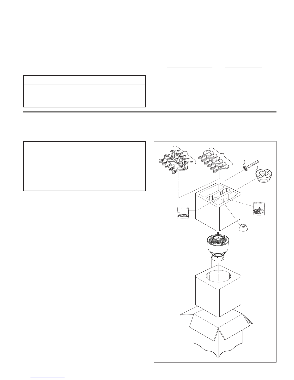
1. Check to see that you have received the following
parts:
Side A
Side B
Downrod/
Hanger Ball
Ceiling Canopy/
Hanger Bracket
NOTE: If you are uncertain of part description, refer to
exploded view illustration. (Figure 20, page 13)
• Fan Motor assembly
• Downrod/Hanger Ball assembly
• Blade Holder pack containing:
– Five blade holders (Side A)
– Five blade holders (Side B)
• Ceiling Canopy
• Hanger Bracket
• Hardware bag:
– Ten 10-32 x 1/2˝ (blade holder to fan
motor assembly) screws
– Two 5/32˝-32 x 19 mm threaded rods
– Two 5/32˝ lockwashers
– Two knurled knobs
– Three wire connectors
– Fanimation pull chain
• Motor Coupling Cover
• Blade Mounting Hardware Bag
– Ten 3/16˝-24 x 1/2˝ screws (for use with
Side A and Side B of the blade holder)
– Fanimation screwdriver
Hardware Bag
Upper Foam
Lower Foam
Packing
Packing
Blade Mounting
Hardware Bag
Motor Coupling
Cover
Fan Motor
Assembly
3
Electrical and Structural Requirements
Your new ceiling fan will require a grounded electrical
supply line of 120 volts AC, 60 Hz, 15 amp circuit. The
outlet box must be securely anchored and capable of
withstanding a load of at least 50 lbs. Figure 1 depicts
different structural configurations that may be used for
mounting the outlet box.
▲
WARNING
To reduce the risk of fire, electrical shock, or personal
injury, mount fan to outlet box marked acceptable for fan
support, and use screws supplied with outlet box. Most
outlet boxes commonly used for support of light fixtures
are not acceptable for fan support and may need to be
replaced. Consult a qualified electrician if in doubt.
Ceiling
Ceiling
Joists
If your fan is to replace an existing light fixture, turn
electricity off at the main fuse box at this time and remove
the existing light fixture.
▲
WARNING
Turning off wall switch is not sufficent. To avoid
possible electrical shock, be sure electricity is turned
off at the main fuse box before wiring. All wiring must
be in accordance with National and Local codes and the
ceiling fan must be properly grounded as a precaution
against possible electrical shock.
2˝ x 4˝
Outlet
Box
Figure 1
▲
WARNING
To avoid fire or shock, follow all wiring instructions
carefully. Any electrical work not described in these
instructions should be done or approved by a licensed
electrician.
How to Assemble Your Ceiling Fan
1. Prior to assembly, set aside and save the hardware
bag(s) packed in the packing.
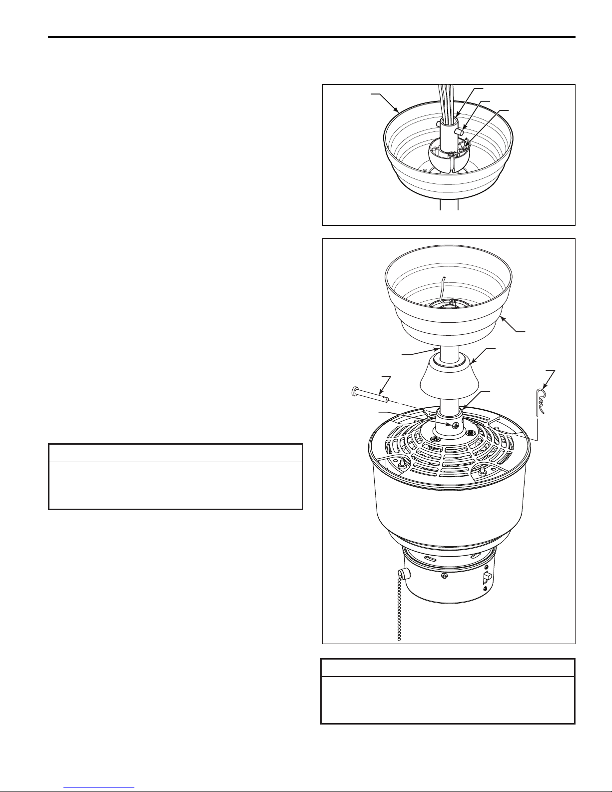
2. Remove the Hanger Ball by loosening the setscrew
in the Hanger Ball until the ball falls freely down the
Downrod. (Figure 2) Remove the Pin from the Downrod,
then remove the Hanger Ball. Retain the Pin and Hanger
Ball for reinstallation in Step 6.
3. The fan comes with blue, black, and white 80˝ wires.
Separate and untwist the three wires. Route the wires
through the Downrod.
Hanger
Ball
Figure 2
Pin
Setscrew
4
How to Assemble Your Ceiling Fan (cont’d)
NOTE: Y ou will be using either the 6˝ downrod supplied with
your fan or an optional downrod purchased seperately.
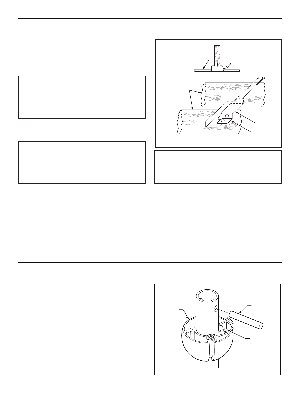
4. Loosen the two setscrews in the Downrod Support.
Align the Clevis Pin holes in the Downrod with the holes
in the Downrod Support. Install the Clevis Pin and secure
with the Hairpin Clip. (Figure 4) Be sure to push the
straight leg of the hairpin clip through the hole near the
end of the clevis pin until the curved portion of the hairpin
clip snaps around the clevis pin. The hairpin clip must be
properly installed to prevent the clevis pin from working
loose. Pull on the Downrod to make sure the clevis pin is
properly installed.
NOTE: The setscrews must be properly installed as
described above, or fan-wobble could result.
5. Route wires through opening in Canopy. Position
Canopy on fan shown with open side facing up. (Figure 3)
6. Reinstall the Hanger Ball (Figure 3) on the Downrod as
follows. Route the three 80˝ wires through the Hanger Ball.
Position the Pin through the two holes in the Downrod and
align the Hanger Ball so the Pin is captured in the groove
in the top of the Hanger Ball. Pull the Hanger Ball up
tight against the pin. Securely tighten the setscrew in
the Hanger Ball. A loose setscrew could create fan
wobble.
Ceiling
Canopy
Downrod/Hanger
Ball Assembly
Clevis Pin
Setscrew
Downrod
Pin
Setscrew
Figure 3
Ceiling
Canopy
Motor Coupling
Cover
Hairpin
Clip
Downrod
Support
▲
WARNING
It is critical that the clevis pin in the downrod support
is properly installed and the setscrews are securely
tightened. Failure to verify that the pin and setscrews
are properly installed could result in the fan falling.
7. While pulling up on the hanger ball, securely tighten
the two 3/16-24 x 3/8˝ setscrews in the downrod support
(Figure 4).
8. Slide the motor coupling cover down until it touches the
top of the motor.
9. The fan comes with blue, black, and white leads. Before
installing fan, measure up approximately 6-9 inches above
top of Downrod/Hanger Ball Assembly. Cut off excess wire
and strip back insulation ½˝ from end of wire.
10. You have now completed the assembly of your new
ceiling fan. You can now proceed with the hanging and
the electrical wiring of your fan.
Figure 4
▲
WARNING
To reduce the risk of personal injury, do not bend the
blade holders when installing, balancing the blades or
cleaning the fan. Do not insert foreign objects in between
the rotating blades.
5
How to Hang Your Ceiling Fan
▲
WARNING
To avoid possible electrical shock, be sure electricity is
turned off at the main fuse box before hanging.
NOTE: If you are not sure if the outlet box is grounded,
contact a licensed electrician for advice, as it must be
grounded for safe operation.
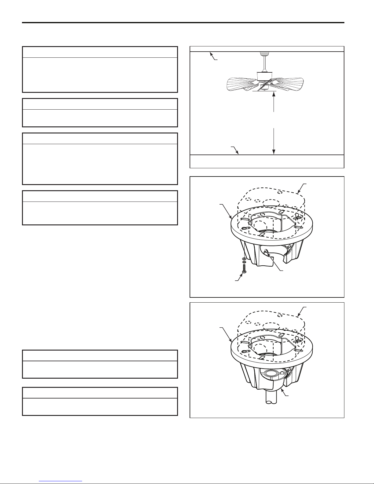
▲
WARNING
The fan must be hung with at least 7´ of clearance from
floor to blades (Figure 5)
▲
WARNING
The outlet box must be securely anchored and capable
of withstanding a load of at least 50 lbs. Hanger bracket
must seat fi rmly against outlet box. If the outlet box is
recessed, remove wallboard until bracket contacts box.
If bracket and/or outlet box are not securely attached,
the fan could wobble or fall.
Ceiling
No
less than
7 ft
Floor
Figure 5
Outlet Box
CAUTION
Do not connect fan blades until the fan is completely
installed. Hanging fan with blades connected may result
in damage to the fan blades.
1. Securely attach the hanger bracket to the outlet box
using the outlet boxscrews and washers supplied with the
outlet box (Figure 6).
NOTE: Outlet box screws pass through slotted holes of
the hanger bracket (Figure 6).
2. Pull the electric wires in the outlet box down through
the opening in the hanger bracket and bend wires up and
out of the way so that the hanger ball will easily fit into the
hanger bracket.
3. Carefully lift the fan and seat the downrod/hanger ball
assembly on the hanger bracket that was just attached to
the outlet box (Figure 7). Be sure the groove in the ball is
lined up with tab on the hanger bracket (Figure 6).
▲
WARNING
Failure to seat tab in groove could cause damage to
electrical wires and possible shock or fire hazard.
Hanger
Bracket
Screw (2)
Supplied with
Outlet Box
Hanger
Bracket
Tab
Figure 6
Outlet Box
▲
WARNING
To avoid possible shock, do not pinch wires between the
downrod/hanger ball assembly and the hanger bracket.
Downrod/Hanger
Ball Assembly
Figure 7
6
How to Wire Your Ceiling Fan - Pull Chain
If you feel that you do not have enough electrical wiring knowledge or experience, have your fan installed by a
licensed electrician.
▲
WARNING
To avoid possible electrical shock, be sure electricity is
turned off at the main fuse box before wiring.
NOTE: If you are not sure if the outlet box is grounded,
contact a licensed electrician for advice, as it must be
grounded for safe operation.
1. Connect the green grounding lead from the hanger ball
and the green grounding lead from the hanger bracket to
the supply grounding conductor (this may be a bare wire
or wire with green colored insulation). Securely connect
wires with wire connectors supplied.
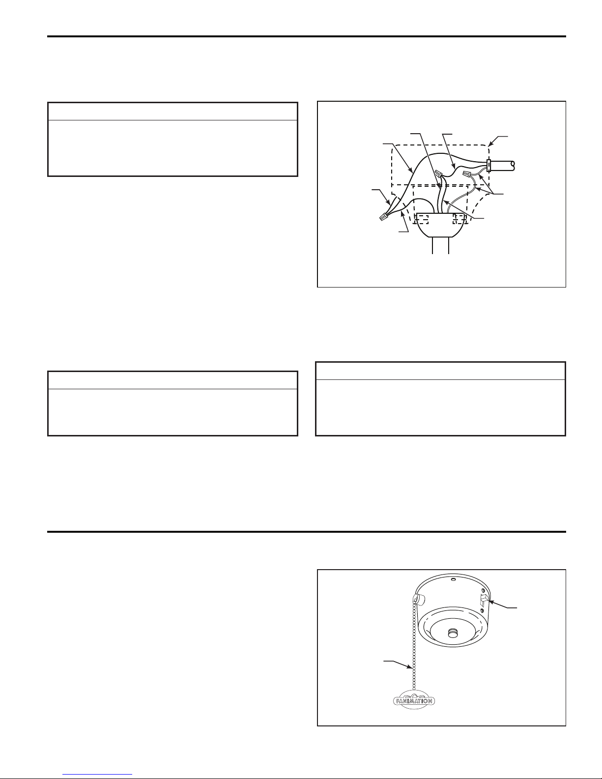
2. Securely connect the white fan motor wire to the white
supply (neutral) wire using wire connector supplied.
Securely connect the black fan motor wire and blue wire
to the black supply wire using wire connector supplied
(Figure 8). After connections have been made, turn leads
upward and carefully push leads into the outlet box, with
the white and green leads on one side of the outlet box
and the black and blue leads on the other side of the outlet
box.
Green Wire
(Ground)
Green Wire
(Ground) from
Hanger Bracket
Green Wire
(Ground) from
Hanger Bowl
3. Secure the ceiling canopy to the hanger bracket with
threaded rods, external lockwashers, and knurled knobs
provided (see page 10). Your fan is now wired to be
turned on and off from the fan pull chain speed control.
Black
Fan Wire
Figure 8
Black
Listed
Outlet Box
Household
Supply
White
Blue
INSTALLATION NOTE
If separate control of light fi xture (optional) is desired,
a separate switch leg from the outlet box is required. In
this instance the blue wire from the fan will be connected
to the light switch leg (typically red wire)
Operating Instructions - Pull Chain
1. Restore electrical power to the outlet box by turning the
electricity on at the main fuse box.
2. Check the operation of the fan by gently pulling on the
pull chain switch. (Figure 9)
3. If airflow is desired in the opposite direction, turn the
fan off and wait for the blades to stop turning. Then slide
the reverse switch to the opposite position and turn fan
on again. Your fan model is equipped with a 4-position,
3-speed, pull chain switch. The operating sequence is as
follows:
1st Pull = HIGH 3rd Pull = LOW
2nd Pull = MEDIUM 4th Pull = OFF
▲
WARNING
Check to see that all connections are tight, including
ground, and that no bare wire is visible at the wire
connectors, except for the ground wire. Do not operate
fan until the blades is in place. Noise and fan damage
could result.
Reversing
Switch
Speed Control
Pull Chain
Figure 9
7
Installing the Canopy Housing
NOTE: This step is applicable after the neccessary wiring
is completed. (see pages 7)
▲
WARNING
To avoid possible fire or shock, make sure that the
electrical wires are completely inside the canopy housing
and not pinched between the housing and the ceiling.
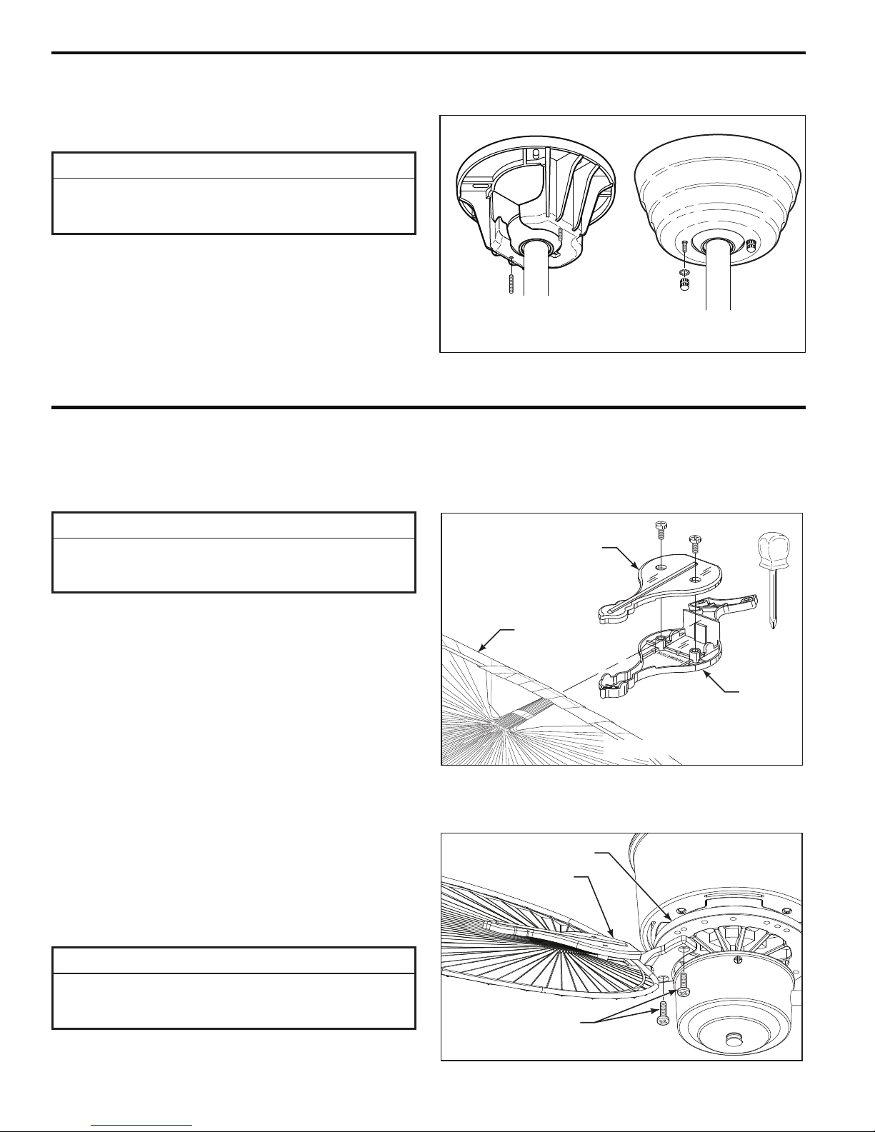
1. Screw in two threaded rods into the Hanger Bracket
(Figure 10a).
NOTE: The threaded rods in the hanger bracket serves as
guides for easier installation.
2. Securely attach the Canopy Housing to the Hanger
Bracket using the external lockwashers and knurled knobs
supplied with your fan (Figure 10b).
NOTE: Supply wires and fan wires omitted for clarity.
Figure 10a Figure 10b
Mounting the Fan Blades
You will fi nd the fan blade set packed in its own carton and the blade holders and hardware bag in the upper foam packing
in the fan box. The hardware bag for the blade holders consists of 10 screws and a Phillips head screwdriver.
INSTALLATION NOTE
Do not connect fan blades until the fan is completely
installed. Installing the fan with blades assembled may
result in damage to the fan blades.
1. Lay side “A” of the blade holder on a flat surface with the
inside of the blade holder facing up. This is the side with
the threaded posts and pitched foot (Figure 11).
2. Position the palm leaf, or the woven bamboo blade, or
the wicker blade over the blade holder with the threaded
posts showing. Make sure the bottom edge of the blade is
fully seated against the blade holder.
3. Place side “B” of the blade holder on top of the blade,
positioning the holes over the threaded posts.
4. With a Philips screwdriver, thread both screws into the
posts but do not fully tighten.
5. Prior to final tightening, position the centerline of the
blade holder with the center of the end of the blade.
Fan Blade
NOTE: Optional Wood blades and Blades Holders,
Canvas blades and The Ococee™ kayak oar blades are
available for this assembly.
Blade Holder
Side B
Side A
Figure 11
Flywheel
6. Tighten both screws to secure the blade. (Figure 12)
INSTALLATION NOTE
Attach the Blades to the Rubber Flywheel using the
holes marked #5 for 5-blade application. For 4-blade
application, use the holes marked #4.
(2 per blade holder)
Screw
Figure 12
8
Mounting the Fan Blades (continued)
7. Attach Blade Holders to the bottom of the Rubber
Flywheel using the 10-32 x ½˝ Flywheel Screws as shown
in Figure 19.
Maintenance
Periodic cleaning of your new ceiling fan is the only
maintenance that is needed.
When cleaning, use only a soft brush or lint free cloth to
avoid scratching the fi nish.
Abrasive cleaning agents are not required and should be
avoided to prevent damage to fi nish.
Blade Cleaning
Periodic light dusting of the Palm Leaf, Woven Bamboo,
or Wicker blades is recommended. A feather duster will
work best.
8. Make sure the screws securing the Blade Holders to
the Flywheel are tight and that the Blade Holders are
properly seated on the Flywheel. (Figure 12)
CAUTION
Do not use water when cleaning your ceiling fan. It
could damage the motor or the blades and create the
possibility of electrical shock.
Avoid using water, cleansers, or harsh rags, which can
warp and ruin the blades.
9
 Loading...