

Fanimation HF6050 Series, HF6600 Series, HF6200 Series Owner's Manual
Standard Fan
Net Weight 12.93 kg
(28.5 lbs)
Standard Leaf Fan
Net Weight 14.51 kg
(32 lbs)
Standard
Presidio Tryne
Net Weight 14.51 kg
(32 lbs)
WARNING: Support Directly From Building Structure
™
Fan
Models No. HF6050, 6200, 6600 Series
OWNER’S MANUAL
READ AND SAVE THESE INSTRUCTIONS
HUBBARDTON FORGE DESIGN, MANUFACTURED AND DISTRIBUTED BY FANIMATION
For Canada, this fan must be secured directly to the building structure or ceiling joist.
Don’t secure this fan to an outlet box.
Important Safety Instructions
WARNING: To avoid fire, shock and serious personal injury, follow these instructions.
1. Read your owner’s manual and safety information before installing your new fan. Review the accompanying assembly diagrams.
2. Before servicing or cleaning unit, switch power off at service panel and lock service panel disconnecting means to prevent power
from being switched on accidentally. When the service disconnecting means cannot be locked, securely fasten a warning device, such
as a tag, to the service panel.
3. Be careful of the fan and blades when cleaning, painting, or working near the fan. Always turn off the power to the ceiling fan before
servicing.
4. Do not insert anything into the fan blades while the fan is operating.
5. Do not operate reversing switch until fan blades have come to a complete stop.
Additional Safety Instructions
1. To avoid possible shock, be sure electricity is turned off at the fuse box before wiring, and do not operate fan without blades.
2. All wiring and installation procedures must satisfy National Electrical Codes (ANSI/ NFPA 70-1999) and Local Codes. The ceiling fan
must be grounded as a precaution against possible electrical shock. Electrical installation should be made or approved by a licensed
electrician.
3. The fan base must be securely mounted and capable of reliably supporting at least 50 lbs. (fan and accessories not to exceed 50 lbs.
or 22.7 kgs.). See page 4 of owner’s manual for support requirements. Consult a qualified electrician if in doubt.
WARNING: Mount only to an outlet box marked acceptable for fan support.
4. The fan must be mounted with the fan blades at least 7 feet from the floor to prevent accidental contact with the fan blades.
5. Follow the recommended instructions for the proper method of wiring your ceiling fan. If you do not have adequate electrical
knowledge or experience, have your fan installed by licensed electrician.
6. Suitable for use with solid-state speed controls.
WARNING: To reduce the risk of fire or electric shock, this fan should only be used with Fan Speed Control Part No. UC7067RC,
manufactured by Rhine Electronic Co., Ltd.
WARNING: TO REDUCE THE RISK OF SHOCK, THIS FAN MUST BE INSTALLED WITH AN ISOLATING WALL CONTROL/SWITCH.
WARNING: This product is designed to use only those parts supplied with this product and/or accessories designated specifically for
use with this product. Using parts and/or accessories not designated for use with this product could result in personal injury or property
damage.
WARNING: To reduce the risk of personal injury, do not bend the blade bracket (flange or blade holder) when installing the brackets,
balancing the blades, or cleaning the fan. Do not insert foreign objects in between rotating fan blades.
LIMITED LIFETIME WARRANTY
Extends to the original purchaser of a Fanimation Fan
1. LIMITED LIFETIME MOTOR WARRANTY - If any part of your fan motor fails, due to a defect in materials or workmanship during
the lifetime of the original purchaser, Fanimation will provide the replacement part free of charge, when the defective fan is returned
to our national service center. Proof of purchase is required. Customer shall be responsible for all costs incurred in the removal or
reinstallation and shipping of the product for repairs or replacement.
2. ONE YEAR MOTOR LABOR WARRANTY - If your fan motor fails at any time within one year from the original purchase, due to
defects in materials or workmanship, labor to repair the motor will be provided free of charge at our national service center. Purchaser
will be responsible for labor charges after this one-year period. Customer shall be responsible for all costs incurred in the removal or
reinstallation and shipping of the product for repairs or replacement.
3. If any other part of your fan fails at any time within one year after original purchase, due to a defect in materials or workmanship, we
will repair, or replace, at our option, the defective part free of charge for parts and labor performed at our national service center.
4. Because of varying climate conditions, this warranty does not cover changes in the finish, including rusting, pitting, corroding,
tarnishing, or peeling.
5. This warranty is void and does not apply to damage from improper installation, neglect, accident, misuse, exposure to extremes of
heat or humidity, or as a result of any modification to the original product.
6. All costs of removal and reinstallation of the fan are the sole responsibility of the owner of the fan and not the store that sold the fan
or Fanimation.
7. Fanimation reserves the right to modify or discontinue any product at any time and may substitute any part under this warranty.
8. Under no circumstances may a fan be returned without prior authorization from Fanimation. The receipt of purchase must accompany authorized returns and must be sent freight prepaid to Fanimation. The fan to be returned must be properly packed to avoid
damage in transit; Fanimation will not be responsible for any damage resulting from improper packaging.
9. It is understood that any repair or replacement is the exclusive remedy available from Fanimation. There is no other expressed or
implied warranty. Fanimation hereby disclaims any and all implied warranties, including, but not limited to those of merchantability and
fitness for a particular purpose to the extent permitted by law. Some states do not allow limitations on implied warranties. Fanimation
will not be liable for incidental, consequential, or special damages arising out of or in conjunction with product use or performance,
except as may otherwise be accorded by law. This warranty gives you special legal rights and you may also have other rights that vary
from state to state.
10. A certain amount of wobble is normal and should not be considered a problem or a defect.
Table of Contents
Unpacking Instructions . . . . . . . . . . . . . . . . . . . . . . . . . . . . . . . . . . . . . . .3
Electrical and Structural Requirements . . . . . . . . . . . . . . . . . . . . . . . . . . 4
How to Assemble Your Down Rod Sleeve . . . . . . . . . . . . . . . . . . . . . . . . 4
How to Assemble Your Ceiling Fan . . . . . . . . . . . . . . . . . . . . . . . . . . . . .6
How to Hang Your Ceiling Fan . . . . . . . . . . . . . . . . . . . . . . . . . . . . . . . . .8
How to Wire Your Ceiling Fan - C20 Remote Control . . . . . . . . . . . . . . . 9
Installing the Canopy Housing . . . . . . . . . . . . . . . . . . . . . . . . . . . . . . . . 10
Assembling and Mounting the Fan Blades . . . . . . . . . . . . . . . . . . . . . . 10
Installing the Receiver Unit and Switch Cup Housing . . . . . . . . . . . . . 11
Maintenance . . . . . . . . . . . . . . . . . . . . . . . . . . . . . . . . . . . . . . . . . . . . . . . 11
Blade Cleaning . . . . . . . . . . . . . . . . . . . . . . . . . . . . . . . . . . . . . . . . . . . . . 11
Parts List . . . . . . . . . . . . . . . . . . . . . . . . . . . . . . . . . . . . . . . . . . . . . . . . . . 12
Exploded-View Drawing. . . . . . . . . . . . . . . . . . . . . . . . . . . . . . . . . . . . . . 13
Installing the Leaf Light Kit – LKHF7260**. . . . . . . . . . . . . . . . . . . . . . . 14
Leaf Light Kit – LKHF7260** — Parts Identifi cation . . . . . . . . . . . . . . . 15
Installing the Presidio Tryne™ Light Kit – LKHF7660** . . . . . . . . . . . . 16
Presidio Tryne™ Light Kit – LKHF7660** — Parts Identifi cation . . . . . 17
Trouble Shooting . . . . . . . . . . . . . . . . . . . . . . . . . . . . . . . . . . . . . . . . . . . 18
This Manual is Designed to Make it as Easy as Possible for You
to Assemble, Install, Operate, and Maintain Your Ceiling Fan
Tools Needed for Assembly Materials
• One Phillips head screwdriver
• One stepladder
• One ¼˝ blade screwdriver
• One wire stripper
• Three wire connectors
(supplied)
Wiring outlet box and box connectors must be of type
required by local code. The minimum wire would be a 3conductor (2-wire with ground) of the following size:
Wire Size A.W.G.Installed Wire Length
▲
WARNING
Before assembling your ceiling fan, refer to section on
proper method of wiring your fan (page 4). If you feel you
do not have enough wiring knowledge or experience,
have your fan installed by a licensed electrician.
Up to 50 ft.
50 - 100 ft.
NOTE: Place the parts from the loose parts bags in a small
container to keep them from being lost. If any parts are missing,
contact your local retailer.
14
12
Unpacking Instructions
For your convenience, check-off each step. As each step is completed, place a check mark. This will ensure that all
steps have been completed and will be helpful in fi nding your place should you be interrupted.
▲
WARNING
Do not install or use fan if any part is damaged or
missing. This product is designed to use only those
parts supplied with this product and/or any accessories
designated specifically for use with this product by
Fanimation. Substitution of parts or accessories not
designated for use with this product by Fanimation could
result in personal injury or property damage. Contact
your retail store for missing or damaged parts.
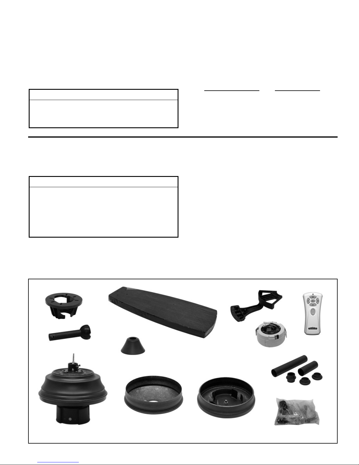
1. Check to see that you have received the following
parts:
• Fan Motor assembly
• Five Blade Holders
• Five Wood Blades
• Hanger Bracket
• Downrod/Hanger Ball
assembly
• Downrod Cover assembly
• Ceiling Canopy
• Motor Coupling Cover
• Switch Cup Cover
• C20 Remote Control
• Receiver Unit
• Hardware bags:
– Two 5/32˝ threaded rods
– Two 5/32˝ lockwashers
– Two knurled knobs
– Two 5/32˝ Flat head screws
– Sixteen 3/16˝ screws
– Sixteen 3/16˝ fiber washers
– Eleven 1/4˝ screws
– Four wire nuts
– Support Safety Cable bag
– Phillips screwdriver, 4˝
– Balance Kit
NOTE: If you are uncertain of part description, refer to
exploded view illustration. (Figure 1, page 13)
Hanger Bracket
Downrod/
Hanger Ball
Assembly
Motor Coupling
Cover
Ceiling Canopy
Fan Motor Assembly
Wood Blade (5)
Blade Holder (5)
C20 Remote
Control
Receiver Unit
Downrod Cover Assembly
Switch Cup Cover
Hardware Bag
3
Electrical and Structural Requirements
Your new ceiling fan will require a grounded electrical
supply line of 120 volts AC, 60 Hz, 15 amp circuit. The
outlet box must be securely anchored and capable of
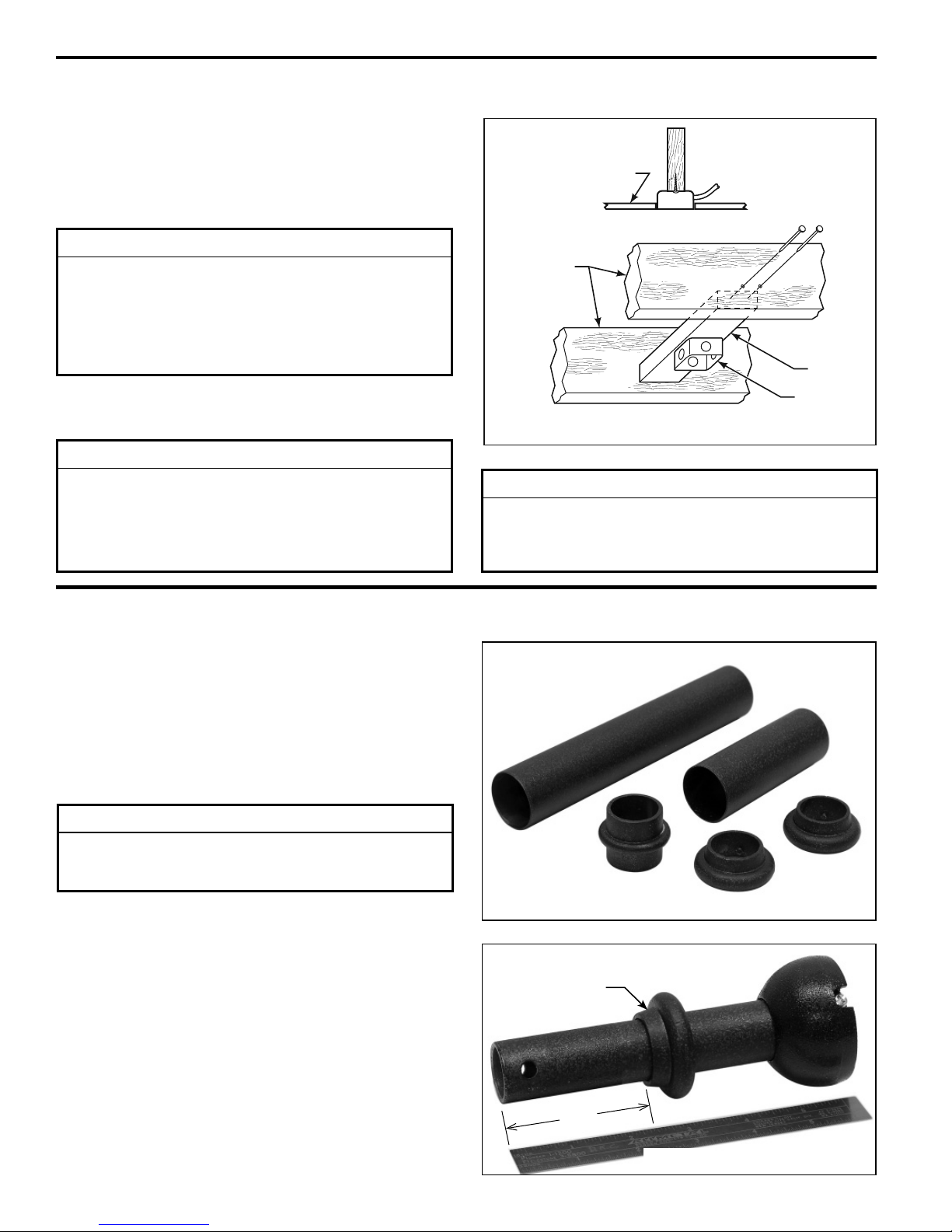
withstanding a load of at least 22.7 kgs (50 lbs). Figure 1
depicts different structural configurations that may be used
for mounting the outlet box.
▲
WARNING
To reduce the risk of fire, electrical shock, or personal
injury, mount fan to outlet box marked acceptable
for fan support of 22.7 kg (50 lbs) or less. Use screws
supplied with outlet box. Most outlet boxes commonly
used for support of light fixtures are not acceptable for
fan support and may need to be replaced. Consult a
qualified electrician if in doubt.
If your fan is to replace an existing light fixture, turn
electricity off at the main fuse box at this time and remove
the existing light fixture.
▲
WARNING
Turning off wall switch is not sufficient. To avoid
possible electrical shock, be sure electricity is turned
off at the main fuse box before wiring. All wiring must
be in accordance with National and Local codes and the
ceiling fan must be properly grounded as a precaution
against possible electrical shock.
Ceiling
Ceiling
Joists
2˝ x 4˝
Outlet
Box
Figure 1
▲
WARNING
To avoid fire or shock, follow all wiring instructions
carefully. Any electrical work not described in these
instructions should be done or approved by a licensed
electrician.
How to Assemble Your Down Rod Sleeve
1. Prior to assembly, set aside and save the hardware
bag(s) packed in the packing.
2. Check to see that you have received the following parts
(Figure 1).
NOTE: You will be using either the 6˝ downrod supplied with
your fan or an optional downrod purchased separately.
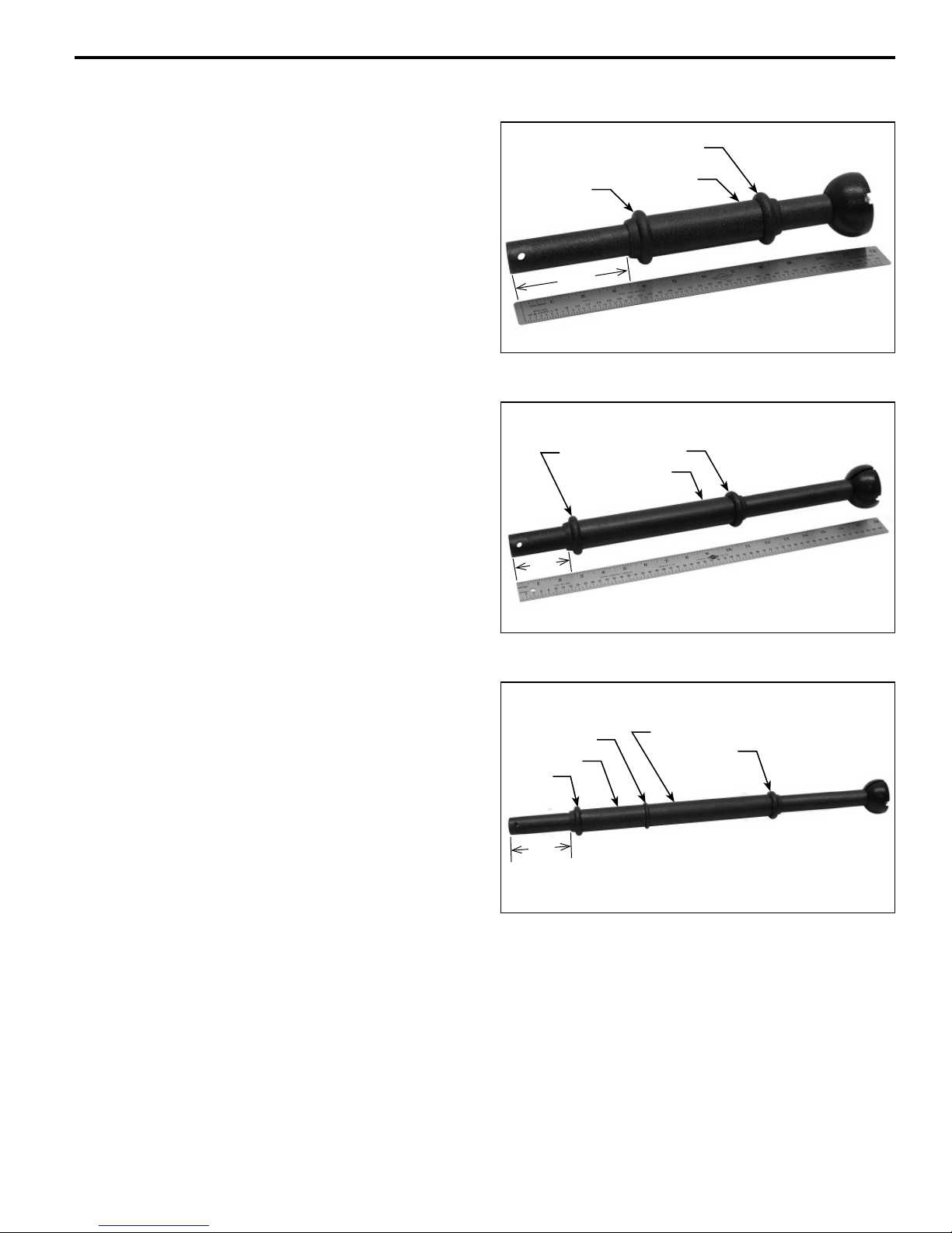
INSTALLATION NOTE
For various Downrod lengths, maintain the distance
between 2½ to 3½ from the bottom of Collar to the end of
Downrod as shown.
6˝ Down Rod Assembly:
3. Assemble one Collar with allen wrench provided, as
shown (Figure 2).
DR1x6
Sleeve, 8˝
Collar
Checkring
Sleeve, 4˝
Collar (2)
Figure 1
2½˝
Figure 2
4
How to Assemble Your Down Rod Sleeve (cont’d)
12˝ Down Rod Assembly:
3. Assemble two Collars and 4˝ Sleeve, as shown
(Figure 3).
18˝ Down Rod Assembly:
4. Assemble the 18˝ Down Rod and the Sleeve Kit in the
order as shown (Figure 4).
DR1x12
DR1x18
2½˝
Collar
3½˝
Collar
Collar
Sleeve, 4˝
Figure 3
Collar
Sleeve, 8˝
24˝ (or longer) Down Rod Assembly:
5. Assemble the 24˝ Down Rod and the Sleeve Kit in the
order as shown (Figure 5).
DR1x24 or Longer
Checkring
Sleeve, 4˝
Collar
3½˝
Figure 4
Sleeve, 8˝
Collar
Figure 5
5
How to Assemble Your Ceiling Fan
1. Prior to assembly, set aside and save the hardware
bag(s) packed in the packing.
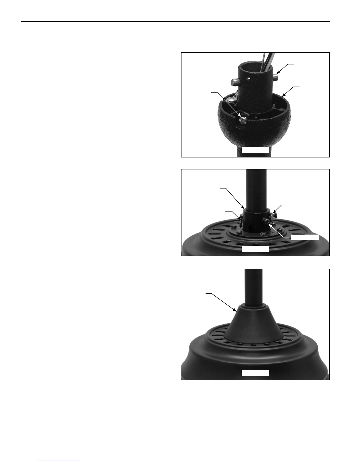
2. Remove the Hanger Ball by loosening the setscrew
in the Hanger Ball until the ball falls freely down the
Downrod. (Figure 1) Remove the Pin from the Downrod,
then remove the Hanger Ball. Retain the Pin and Hanger
Ball for reinstallation in Step 8.
3. The fan comes with support cable, black and white 80˝
wires. Separate and untwist the wires & cable. Route the
wires & cable through the Downrod.
Setscrew
Pin
Hanger
Ball
NOTE: You will be using either the 6˝ downrod supplied with
your fan or an optional downrod purchased separately.
4. Position Fan/Motor Assembly on styrofoam, for ease of
assembly.
5. Loosen the two setscrews in the Downrod Support. Align
the Clevis Pin holes in the Downrod with the holes in the
Downrod Support. Install the Clevis Pin and secure with
the Hairpin Clip. (Figure 2) Be sure to push the straight
leg of the hairpin clip through the hole near the end of the
clevis pin until the curved portion of the hairpin clip snaps
around the clevis pin. The hairpin clip must be properly
installed to prevent the clevis pin from working loose. Pull
on the Downrod to make sure the clevis pin is properly
installed. (Figure 2)
6. While pulling up on the hanger ball, securely tighten the
two setscrews with nuts in the downrod support.
(Figure 2)
NOTE: The setscrews must be properly installed as
described above, or fan-wobble could result.
7. Install the Motor Coupling Cover as shown. (Figure 3)
Figure 1
Downrod
Support
Clevis Pin
Hairpin Clip
Setscrew (2)
Figure 2
Motor
Coupling
Cover
Figure 3
6
 Loading...