

Page 1
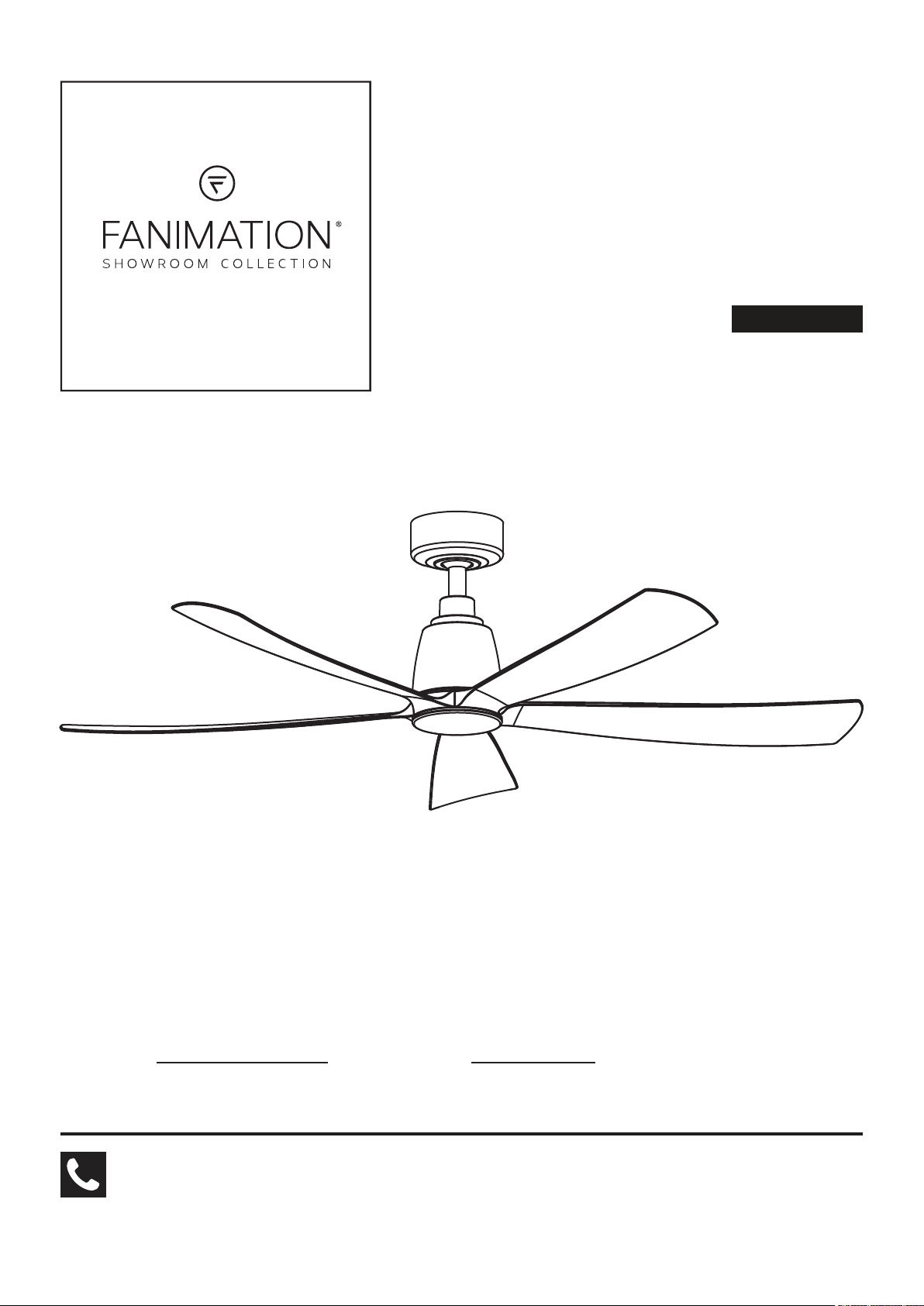
KUTE5 ™ 52 CEILING FAN
MODEL #FPD5534**
Español p. 25
ATTACH YOUR RECEIPT HERE AND REGISTER YOUR FAN AT FANIMATION.COM
READ AND SAVE THESE INSTRUCTIONS
Date Code
For best and quickest service please provide date code. You can find the date code on the carton,
hand-held remote (inside of the battery compartment), receiver or top of fan housing.
Questions, problems, missing parts? Before returning to your retailer, call our customer
service department at 1-888-567-2055, 8 a.m.-5 p.m., EST, Monday-Friday.
Purchase Date
Net Weight 11.69 lbs (5.30 kgs)
Page 2
Important Safety Instructions
WARNING: To avoid fire, shock and serious personal injury, follow these instructions.
1. Read your owner’s manual and safety information before installing your new fan. Review the accompanying assembly diagrams.
2. Before servicing or cleaning unit, switch power off at service panel and lock service panel disconnecting means to prevent power
from being switched on accidentally. When the service disconnecting means cannot be locked, securely fasten a warning device,
such as a tag, to the service panel.
3. Be careful of the fan and blades when cleaning, painting, or working near the fan. Always turn off the power to the ceiling fan before
servicing.
4. Do not insert anything into the fan blades while the fan is operating.
5. The appliance is not intended for use by young children or infirm persons without supervision. Young children should be supervised
to ensure that they do not play with the appliance.
Additional Safety Instructions
1. To avoid possible shock, be sure electricity is turned off at the fuse box before wiring, and do not operate fan without blades.
2. All wiring and installation procedures must satisfy National Electrical Codes (ANSI/ NFPA 70) and Local Codes. The ceiling fan
must be grounded as a precaution against possible electrical shock. Electrical installation should be made or approved by a licensed
electrician.
3. The fan base must be securely mounted and capable of reliably supporting at least 35 lbs. See page 5 of owner’s manual for
support requirements. Consult a qualified electrician if in doubt.
4. The fan must be mounted with the fan blades at least 7 feet from the floor to prevent accidental contact with the fan blades.
5. Follow the recommended instructions for the proper method of wiring your ceiling fan. If you do not have adequate electrical
knowledge or experience, have your fan installed by licensed electrician.
6. Suitable for use with solid-state speed controls.
7. This fan is to be used in damp locations.
8. Use only with light kits marked suitable for use in damp locations.
9. For supply connections, if the conductor of a fan is identified as a grounded conductor, then it should be connected to a grounded
conductor power supply. If the conductor of a fan is identified as an ungrounded conductor, then it should be connected to an
ungrounded conductor power supply. If the conductor of a fan is identified for equipment grounding, then it should be connected to
an equipment grounding conductor.
10. The remote control of this product contain lithium button/coin cell batteries. If a new or used lithium button/coin cell battery is
swallowed or enters the body, it can cause severe internal burns and can lead to death in as little as 2 hours. Always completely
secure the battery compartment. If the battery compartment does not close securely, stop using the remote control of the product,
remove the batteries, and keep it away from children. If you think batteries might have been swallowed or placed inside any part of
the body, seek immediate medical attention.
- The cells shall be disposed of properly, including keeping them away from children.
- Even used cells may cause injury.
11. Turn off wall control can override any smart enabled appliance or remote control commands.
WARNING: Chemical Burn Hazard. Keep batteries away from children.
WARNING: TO REDUCE THE RISK OF ELECTRIC SHOCK, THIS FAN MUST BE INSTALLED WITH A GENERAL USE ISOLATING
WALL CONTROL/SWITCH.
WARNING: This product is designed to use only those parts supplied with this product and/or accessories designated specifically for
use with this product. Using parts and/or accessories not designated for use with this product could result in personal injury
or property damage.
WARNING: To reduce the risk of personal injury, do not bend the blade when installing the fan blades, balancing the blades, or cleaning
the fan. Do not insert foreign objects in between rotating fan blades.
WARNING: Do not operate this fan with a variable (Rheostat) wall controller or dimmer switch. Doing so could result in damage to the
ceiling fan’s remote control unit.
WARNING: Mount to an outlet box marked acceptable for fan support of 15.9 kg (35 lbs) or Less.
This device complies with Part 15 of the FCC Rules. Operation is subject to the following two conditions:
(1) This device may not cause harmful interference, and (2) this device must accept any interference received, including
interference that may cause undesired operation. Please note that changes or modifications not expressly approved by the
party responsible for compliance could void the user's authority to operate the equipment.
Note: This equipment has been tested and found to comply with the limits for Class B digital device, pursuant to part 15 of
the FCC Rules. These limits are designed to provide reasonable protection against harmful interference in a residential
installation.
This equipment generates, uses and can radiate radio frequency energy and, if not installed and used in accordance with the
instructions, may cause harmful interference to radio or television reception, which can be determined by turning the
equipment off and on, the user is encouraged to try to correct the interference by one or more of the following measures:
- Reorient or relocate the receiving antenna.
- Increase the separation between the equipment and the receiver.
- Connect the equipment into an outlet on a circuit different from that to which the receiver is connected.
Consult the dealer or an experienced radio/TV technician for help.
Page 3
Extends to the original purchaser of a Fanimation fan from an authorized Fanimation dealer/retailer only
LIMITED LIFETIME WARRANTY
1. LIMITED LIFETIME MOTOR WARRANTY - If any part of your fan motor fails, due to a defect in materials or workmanship during the
lifetime of the original purchaser, Fanimation will provide the replacement part free of charge, when the defective fan is returned
to our national service center. Proof of purchase is required. Customer shall be responsible for all costs incurred in the removal or
reinstallation and shipping of the product for repairs or replacement.
2. ONE YEAR MOTOR LABOR WARRANTY - If your fan motor fails at any time within one year from the original purchase, due to
defects in materials or workmanship, labor to repair the motor will be provided free of charge at our national service center. Purchaser
will be responsible for labor charges after this one-year period. Customer shall be responsible for all costs incurred in the removal or
reinstallation and shipping of the product for repairs or replacement.
3. If any other part of your fan fails at any time within one year after original purchase, due to a defect in materials or workmanship, we
will repair, or replace, at our option, the defective part free of charge for parts and labor performed at our national service center.
4. Because of varying climate conditions, this warranty does not cover changes in the finish, including rusting, pitting, corroding,
tarnishing, or peeling.
5. This warranty is void and does not apply to damage from improper installation, neglect, accident, misuse, exposure to extremes of
heat or humidity, or as a result of any modification to the original product.
6. All costs of removal and reinstallation of the fan are the sole responsibility of the owner of the fan and not the store that sold the fan or
Fanimation.
7. Fanimation reserves the right to modify or discontinue any product at any time and may substitute any part under this warranty.
8. Under no circumstances may a fan be returned without prior authorization from Fanimation. The receipt of purchase must accompany
authorized returns and must be sent freight prepaid to Fanimation. The fan to be returned must be properly packed to avoid
damage in transit; Fanimation will not be responsible for any damage resulting from improper packaging.
9. It is understood that any repair or replacement is the exclusive remedy available from Fanimation. There is no other expressed or
implied warranty. Fanimation hereby disclaims any and all implied warranties, including, but not limited to those of merchantability and
fitness for a particular purpose to the extent permitted by law. Some states do not allow limitations on implied warranties. Fanimation will
not be liable for incidental, consequential, or special damages arising out of or in conjunction with product use or performance, except as
may otherwise be accorded by law. This warranty gives you special legal rights and you may also have other rights that vary from state to
state.
10. A certain amount of wobble is normal and should not be considered a problem or a defect.
Table of Contents
Unpacking Instructions . . . . . . . . . . . . . . . . . . . . . . . . . . . . . . . . . . . . . . . .
Energy Efficient Use of Ceiling Fans . . . . . . . . . . . . . . . . . . . . . . . . . . . . .
Electrical and Structural Requirements . . . . . . . . . . . . . . . . . . . . . . . . . .
How to Assemble Your Ceiling Fan . . . . . . . . . . . . . . . . . . . . . . . . . . . . . .
How to Hang Your Ceiling Fan . . . . . . . . . . . . . . . . . . . . . . . . . . . . . . . . . .
How to Wire Your Ceiling Fan . . . . . . . . . . . . . . . . . . . . . . . . . . . . . . . . . .
How to Install Your Canopy Housing . . . . . . . . . . . . . . . . . . . . . . . . . . . .
How to Assemble Your Ceiling Fan Blades and Cap . . . . . . . . . . . . . . .
How to Operate Your Ceiling Fan . . . . . . . . . . . . . . . . . . . . . . . . . . . . . . .
10
12
13
14
4
How to Install Your Remote Control . . . . . . . . . . . . . . . . . . . . . . . . . . . . .
5
How to Set Up the fanSync WiFi APP . . . . . . . . . . . . . . . . . . . . . . . . . . . .
5
Maintenance . . . . . . . . . . . . . . . . . . . . . . . . . . . . . . . . . . . . . . . . . . . . . . . .
7
How to Clean Your Ceiling Fan Blades . . . . . . . . . . . . . . . . . . . . . . . . . . .
9
Troubleshooting . . . . . . . . . . . . . . . . . . . . . . . . . . . . . . . . . . . . . . . . . . . . .
Parts List . . . . . . . . . . . . . . . . . . . . . . . . . . . . . . . . . . . . . . . . . . . . . . . . . . .
Exploded-View Illustration . . . . . . . . . . . . . . . . . . . . . . . . . . . . . . . . . . . . .
Optional Light Kit . . . . . . . . . . . . . . . . . . . . . . . . . . . . . . . . . . . . . . . . . . . .
16
17
20
20
20
21
22
23
Page 4
This manual is designed to make it as easy as possible for you to assemble,
install, operate and maintain your ceiling fan
Tools Needed for Assembly
(Not Included)
• One Phillips head screwdriver
• One ¼˝ blade screwdriver
WARNING
Before assembling your ceiling fan, refer to section on
proper method of wiring your fan (page 10). If you feel you
do not have enough wiring knowledge or experience, have
your fan installed by a licensed electrician.
• One stepladder
• One wire stripper
Wiring outlet box and box connectors must be of type
required by local code. The minimum wire would be a 3conductor (2-wire with ground) of the following size:
nstalled ire ength
p to ft
NOTE: Place the parts from the loose parts bags in a small
container to keep them from being lost. If any parts are
missing, contact your local retailer.
Materials
ire i e
ft
Unpacking Instructions
For your convenience, check-off each step. As each step is completed, place a check mark. This will ensure that all steps have been
completed and will be helpful in finding your place should you be interrupted.
WARNING
Do not install or use fan if any part is damaged or missing. This product is designed to use only those parts supplied with
this product and/or any accessories designated specifically for use with this product by Fanimation. Substitution of parts
or accessories not designated for use with this product by Fanimation could result in personal injury or property damage.
Contact your retail store for missing or damaged parts.
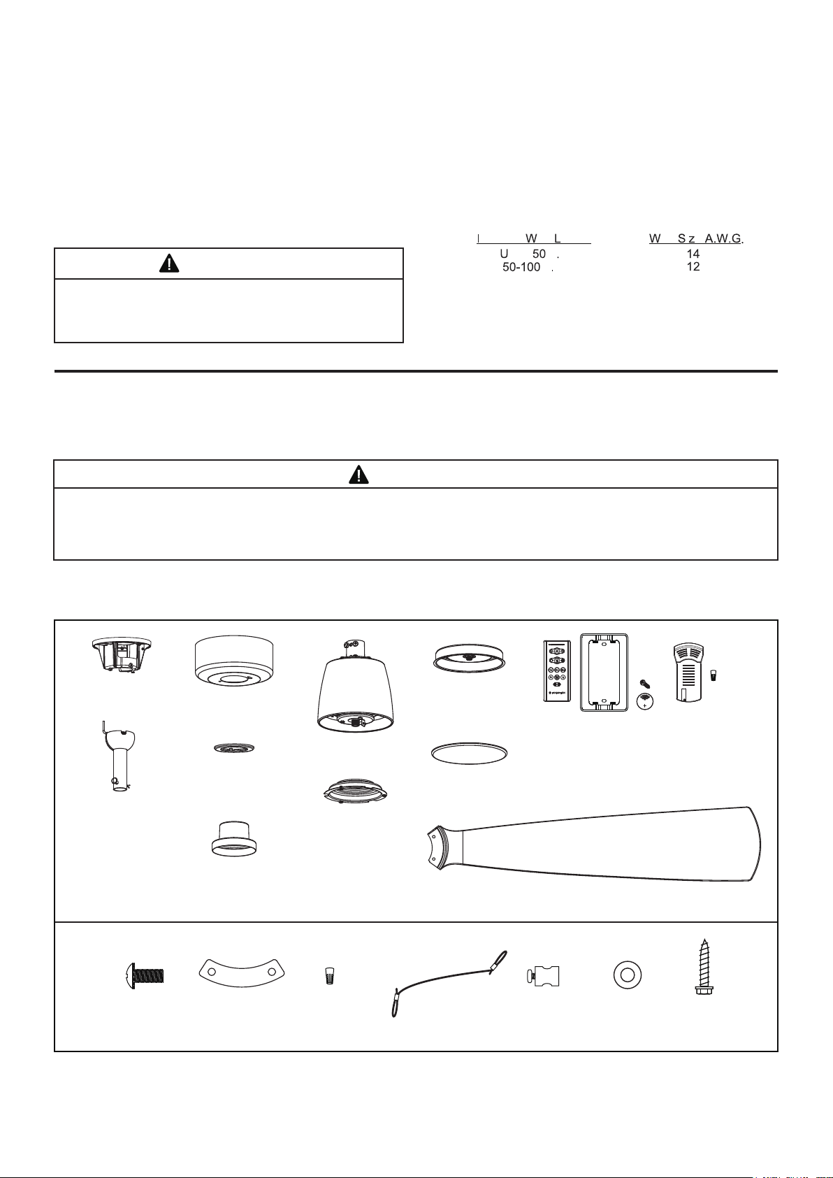
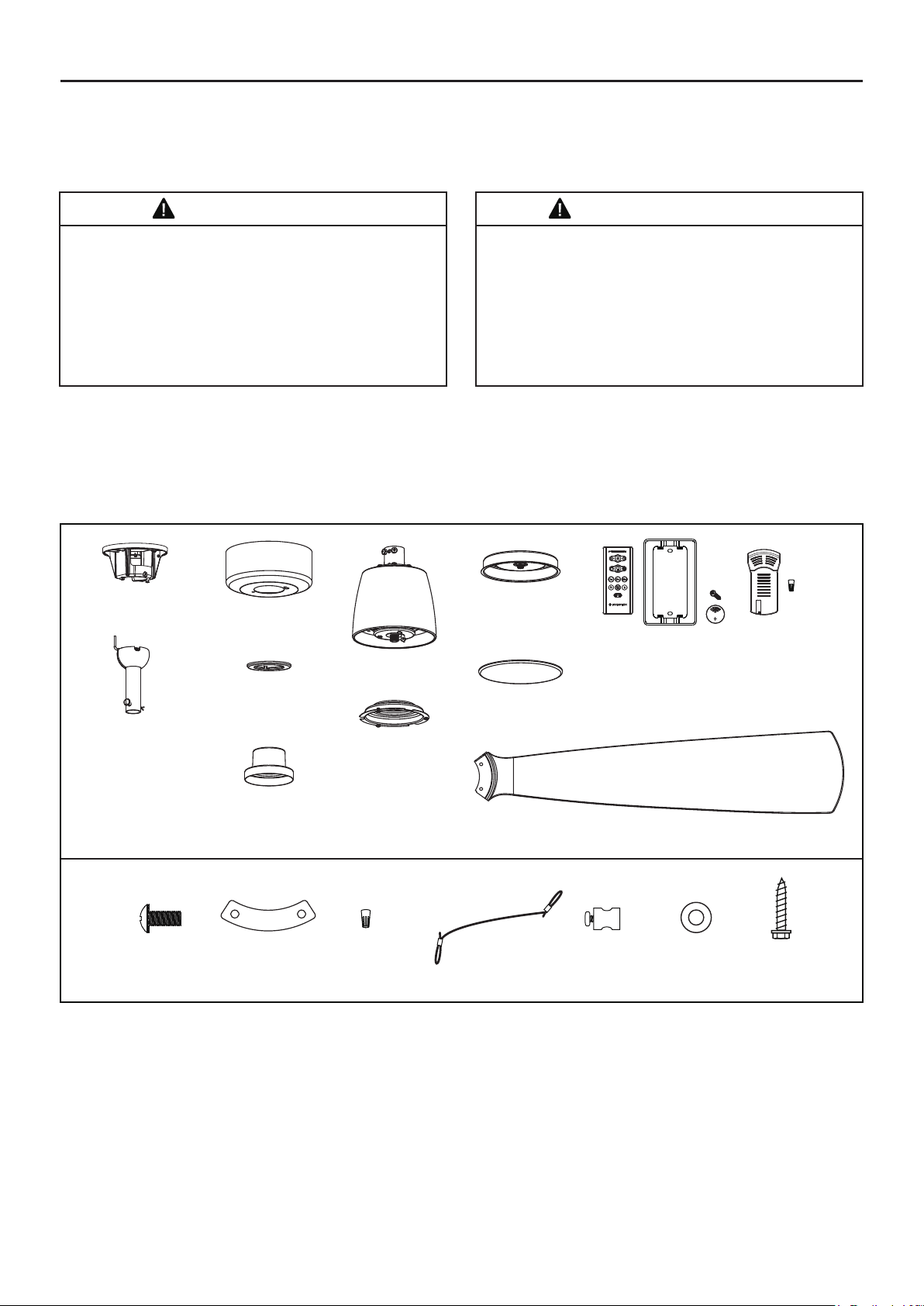
1. Check to see that you have received the following parts:
NOTE: If you are uncertain of part description, refer to exploded view illustration.
Hanger Bracket
Assembly (1)
Downrod/Hanger Ball
Assembly (1)
– Downrod (1)
– Hanger Ball (1)
– Set Screw (1)
– Hairpin Clip (1)
– Clevis Pin (1)
– Pin (1)
Hardware Bags Safety Cable Kit
Ceiling Canopy (1)
Motor Assembly (1)
Canopy Screw
Cover Assembly (1)
Light Plate Assembly (1)
Motor Coupling
Cover Assembly (1)
Light Kit Wire Cover
Assembly (1)
Steel Cap (1)
Blade Set (1)
Hand-held Remote (1)
Wall Plate (1)
Screws (2)
Batteries (2)
Receiver (1)
Wire Connectors (9)
3/16”-24
Serrated Head Screws
(11)
Blade Plates
(5)
Wire Connectors
(4)
Safety Cable
4
(1)
Cable Clamp
(1)
Flat Washer,
Stainless Steel
(1)
Lag Bolt
(1)
Page 5
Energy Efficient Use of Ceiling Fans
Ceiling fan performance and energy savings rely
heavily on the proper installation and use of the
ceiling fan. Here are a few tips to ensure efficient
product performance.
Choosing the Appropriate Mounting Location
Ceiling fans should be installed, or mounted, in the middle
of the room and at least 7 feet from floor to the blade and
18 inches from wall to the blade. If ceiling height allows,
install the fan 8 - 9 feet from floor to the blade for optimal
airflow. Consult your Fanimation Retailer for optional
mounting accessories.
Turn Off When Not in the Room
Ceiling fans cool people, not rooms. If the room is
unoccupied, turn off the ceiling fan to save energy.
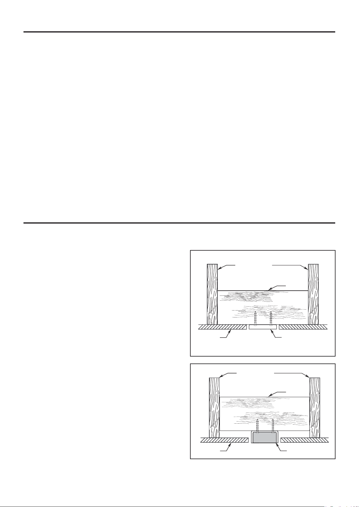
Electrical and Structural Requirements
Your new ceiling fan will require a grounded electrical
supply line of 120 volts AC, 60 HZ, 15 Amp Circuit.
Electrical code requires use of a fan-rated outlet box to
support the extra weight and motion associated with a
ceiling fan. A fan-rated box will be labeled as such and
typically supports up to a 70lb ceiling fan. Fan-Rated
Outlet Boxes vary in ratings and design. Ensure the
ratings of your ceiling fan outlet box meet the
requirements for the ceiling fan being installed. Figure
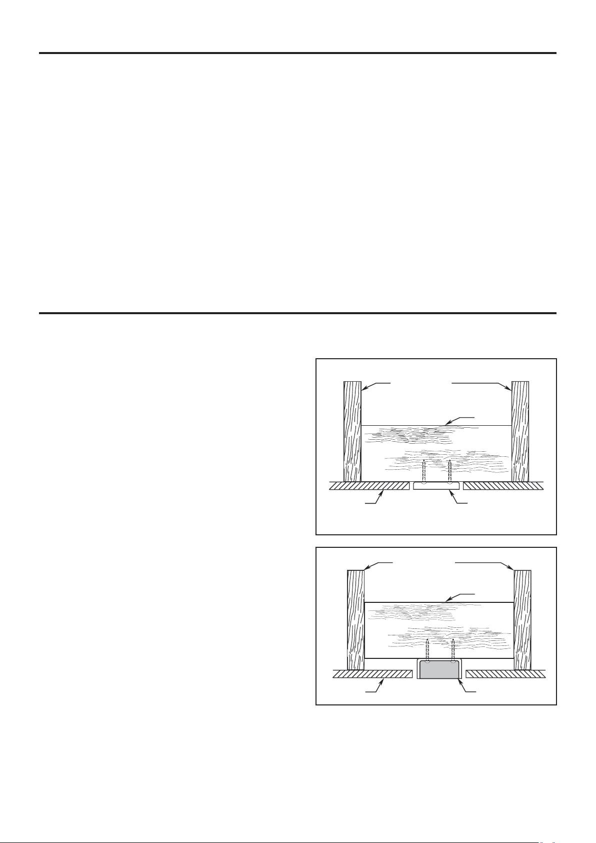
1, Figure 2 and Figure 3 depicts different structural
configurations that may be used for mounting the outlet
box.
Using the Ceiling Fan Year Round
Summer Season: Use the ceiling fan in the
counterclockwise direction. The airflow produced by
the ceiling fan creates a wind-chill effect, making you
“feel” cooler. Select a fan speed that provides a
comfortable breeze, lower speeds consume less
energy.
Winter Season: Reverse the motor and operate the
ceiling fan at low speed in the clockwise direction.
This produces a gentle updraft, which forces warm air
near the ceiling down into the occupied space.
Remember to adjust your thermostat when using your
ceiling fan-additional energy and dollar savings could
be realized with this simple step!
CEILING JOIST
2" x 4"
CEILING
OUTLET BOX
Low profile box (Figure 1)
A 1/2-in.-deep pancake box is meant to be screwed to a
joist or block. It’s used if only one cable is coming into the
box. It is also available in a saddle-mount configuration.
Deep box (Figure 2)
A 2-1/4-in.-deep box can be attached to blocking between
joists and is roomy enough to handle more than one cable.
5
CEILING
Figure 1
CEILING JOIST
Figure 2
2" x 4"
OUTLET BOX
Page 6
Electrical and Structural Requirements (Continued)
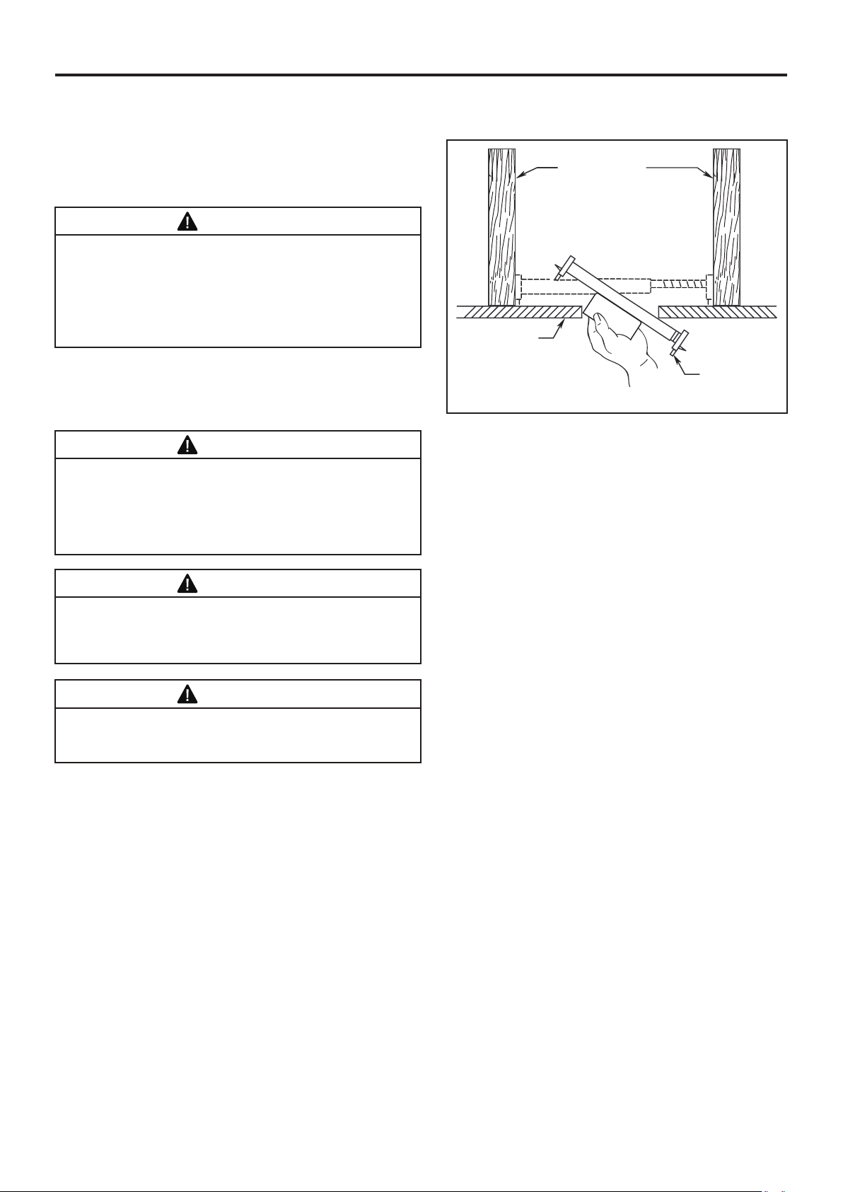
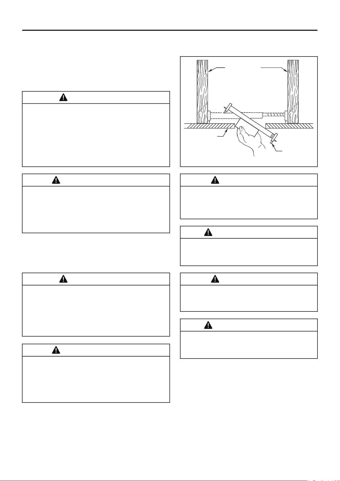
Deep box with brace (Figure 3)
Paired with a deep box, this hanger is meant to span
between two joists and takes the place of wooden blocking.
WARNING
To reduce the risk of fire, electric shock, or personal injury,
mount to outlet box marked acceptable for fan support of
15.9 kg (35 lbs) or less and use mounting screws provided
with the outlet box. Most outlet boxes commonly used for
the support of luminaires are not acceptable for fan support
and may need to be replaced, consult a qualified electrician
if in doubt.
CEILING JOIST
CEILING
If your fan is to replace an existing light fixture, turn
electricity off at the main fuse box at this time and remove
the existing light fixture.
WARNING
Turning off wall switch is not sufficient. To avoid
possible electrical shock, be sure electricity is turned off
at the main fuse box before wiring. All wiring must be in
accordance with National and Local codes and the ceiling
fan must be properly grounded as a precaution against
possible electrical shock.
WARNING
To avoid fire or shock, follow all wiring instructions
carefully. Any electrical work not described in these
instructions should be done or approved by a licensed
electrician.
WARNING
Do not operate this fan with a variable (Rheostat) wall
controller or dimmer switch. Doing so could result in
damage to the ceiling fan’s remote control unit.
OUTLET BOX
Figure 3
6
Page 7
How to Assemble Your Ceiling Fan
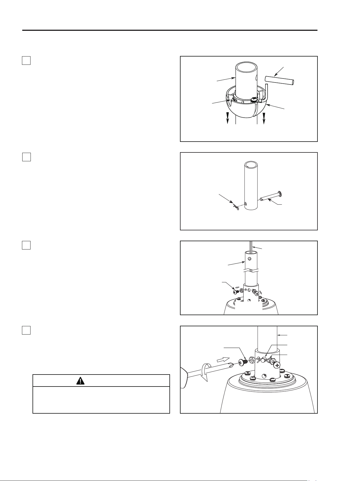
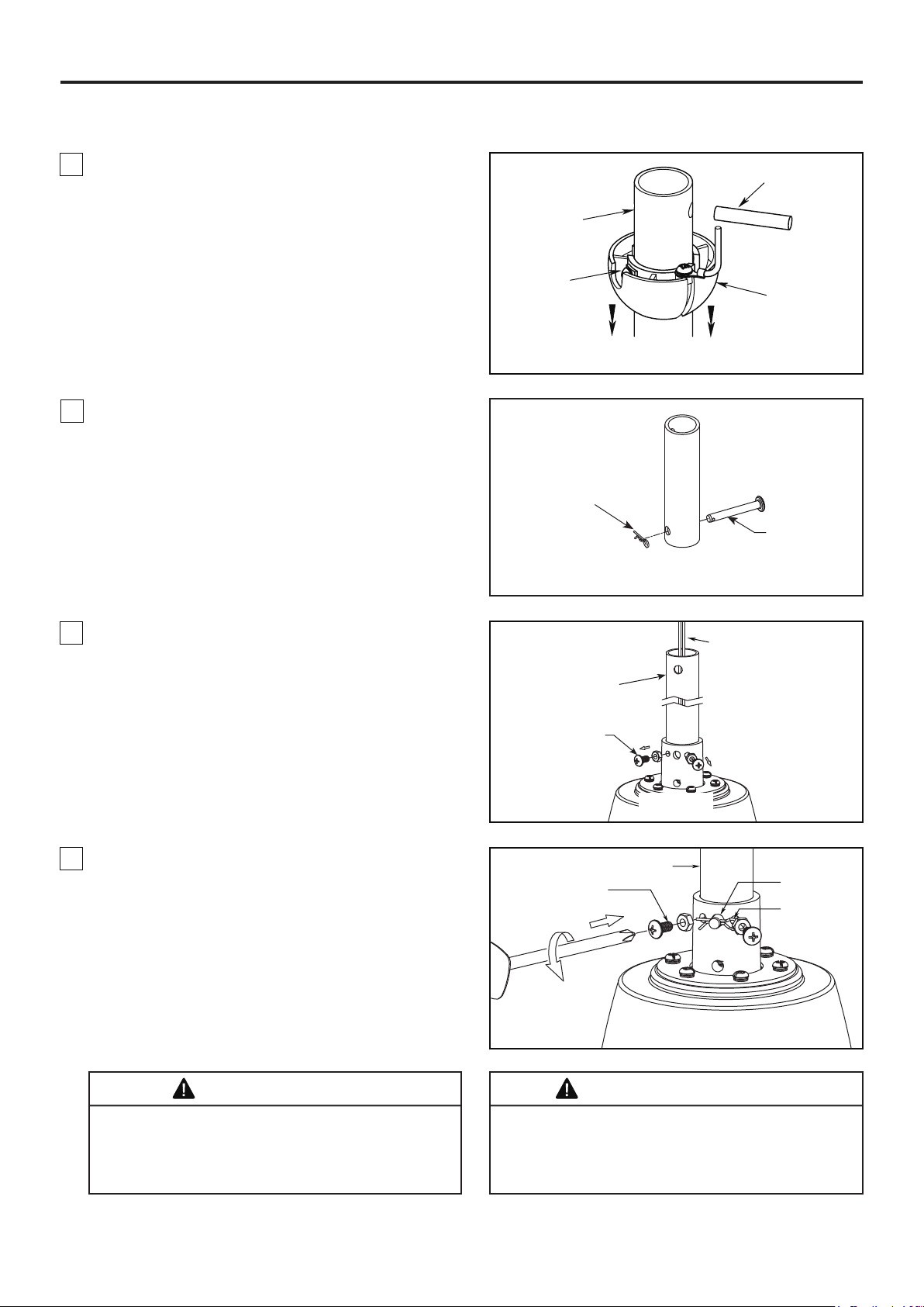
1. Remove the hanger ball portion from the downrod/
hanger ball assembly by loosening the set screw in
the hanger ball until the ball falls freely down the
downrod. Remove the pin from the downrod, then
remove the hanger ball. Retain the pin and hanger
ball for reinstallation in Step 6. (Figure 1)
2. Remove the hairpin clip and clevis pin from the
bottom of the downrod. Retain the pin and clip for
reinstallation in Step 4. (Figure 2)
Pin
Downrod
Set Screw
Hanger Ball
Figure 1
Hairpin Clip
Clevis Pin
Figure 2
3. Loosen the two set screws and locking nuts in the
downrod support of the motor assembly. Route the
brown, blue, red, gray, yellow wires and safety cable
through the downrod. (Figure 3)
4. Slide downrod into the downrod support on top of
the motor. Install the clevis pin by aligning the holes
in the downrod support with holes in the downrod.
Secure clevis pin with hairpin clip. Install and tighten
the two previously removed set screws with nuts in
the downrod support. (Figure 4)
WARNING
It is critical that the clevis pin in the downrod support
is properly installed and the set screws and nuts are
securely tightened. Failure to do so could result in the
fan falling.
Downrod
Set Screws and
Locking Nuts (2)
Set Screws and
Locking Nuts (2)
Brown, Blue, Red, Gray,
Yellow wires and Safety
Cable
Figure 3
Downrod
Clevis Pin
Hairpin Clip
Figure 4
7
Page 8
How to Assemble Your Ceiling Fan (Continued)
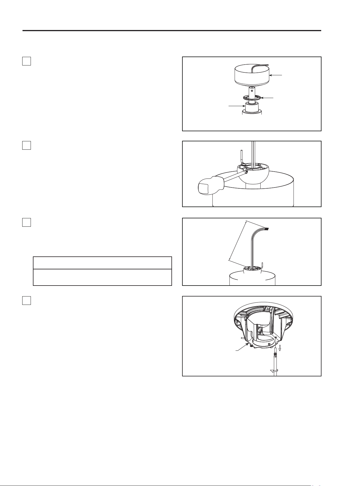
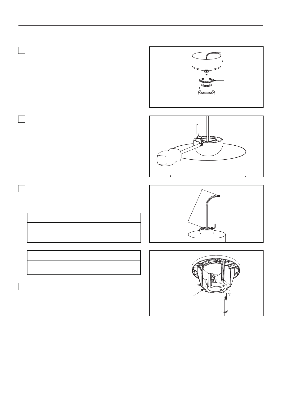
5. Route wires and safety cable through motor
coupling cover, canopy screw cover and ceiling
canopy. (Figure 5)
6. Reinstall the hanger ball on the downrod as follows.
Route the brown, blue, red, gray, yellow wires and
safety cable through the hanger ball. Position the pin
through the two holes in the downrod and align the
hanger ball so the pin is captured in the groove in the
top of the hanger ball. Pull the hanger ball up tight
against the pin. Securely tighten the set screw in the
hanger ball. A loose set screw could cause fan
wobble. (Figure 6)
Ceiling Canopy
Canopy Screw
Cover
Motor Coupling
Cover
Figure 5
Figure 6
7. Cut off excess lead wire approximately 6 to 9 inches
above top of the downrod. Strip insulation off 1/2 inch
from the end of each lead wire. (Figure 7)
CAUTION
All set screws must be checked, and retightened where
necessary before installation.
8. Remove one of the two shoulder screws in the
hanger bracket and retain the screw for later. Loosen
the second shoulder screw without fully removing it.
(Figure 8)
6 to 9 in.
Figure 7
Hanger Bracket
Figure 8
8
Page 9
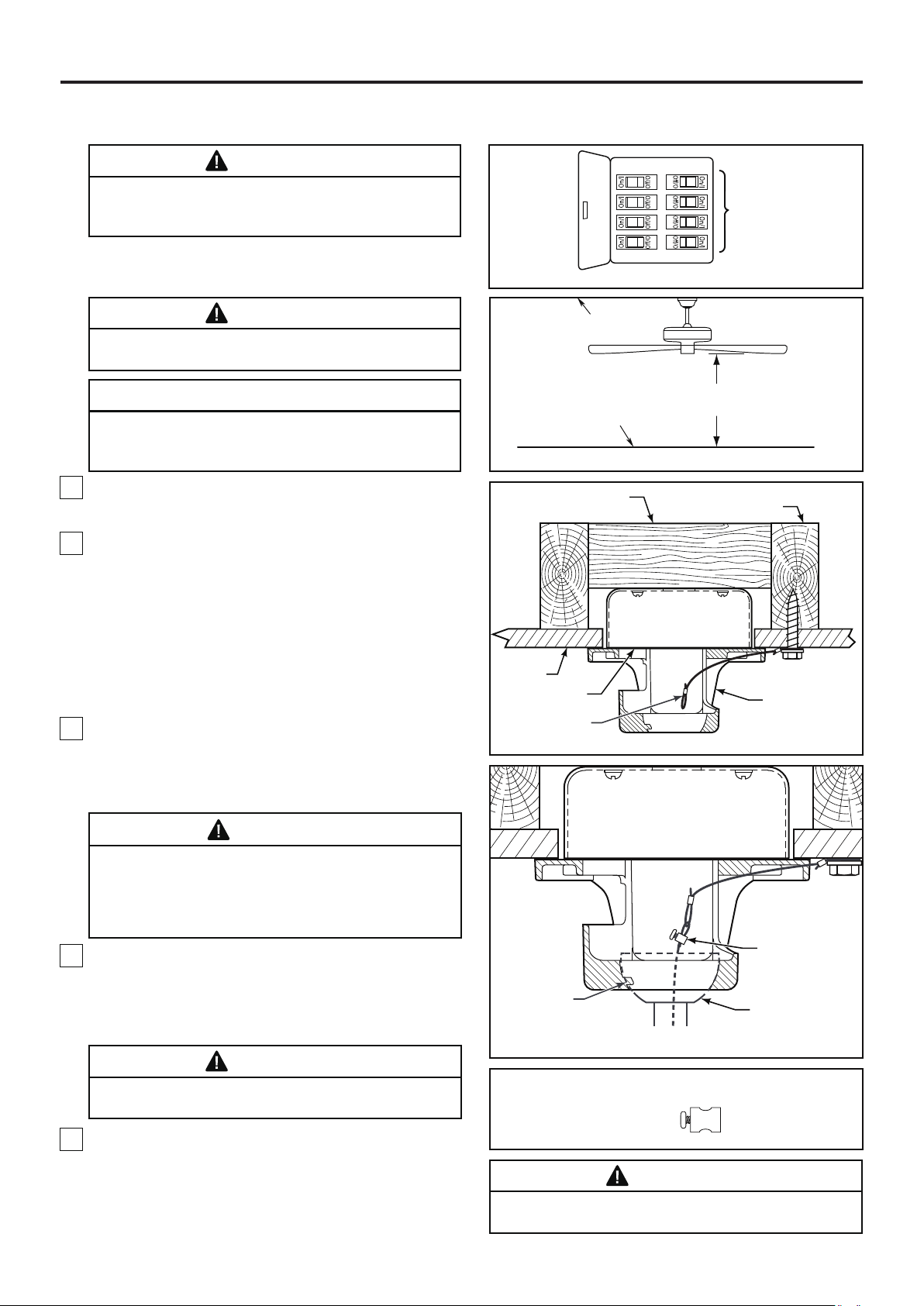
How to Hang Your Ceiling Fan
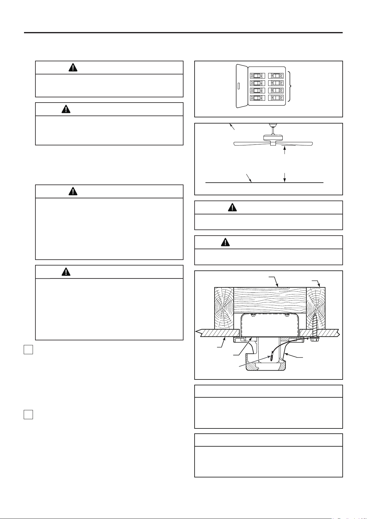
WARNING
To avoid possible fire or shock, be sure electricity is
turned off at the main fuse box before hanging.
(Figure 1)
NOTE: If you are not sure if the outlet box is grounded,
contact a licensed electrician for advice, as it must be
grounded for safe operation.
Main Fuse Box
Figure 1
WARNING
The fan must be hung with at least 7’ of clearance from
floor to blades. (Figure 2)
CAUTION
Do not connect fan blades until the fan is completely
installed. Hanging fan with blades connected may
result in damage to the fan blades.
1. Securely attach the hanger bracket to the outlet box
using the outlet box screws and washers supplied with
the outlet box. (Figure 3)
2. Drill a 1/4" pilot hole into the building structure to
prevent splitting or cracking with installation of the lag
bolt. Using the 3/8" x 2" lag bolt and flat washer, attach
safety cable to ceiling joist or wood structural member.
The lag bolt will pass through the flat washer, safety
cable loop, and into the building structure. (Figure 3)
NOTE: Ceiling support cable cannot be secured to
outlet box only, it must be directly secured to ceiling
joist or structural member using the 3/8" x 2" lag bolt
and flat washer. (Figure 3)
3. Make sure the electrical supply wires, including the
hanger bracket grounding wire and safety cable are
pulled through the downrod, between the hanger
bracket and the outlet box so that electrical
connections can be made later.
Wood Member
(2" x 4" Approx.)
Ceiling
Outlet Box
Ceiling Support
Cable
Ceiling
Floor
Figure 2
Figure 3
No Less
Than
7 Feet
Ceiling Joist
Hanger Bracket
WARNING
The outlet box must be securely anchored. Hanger
bracket must seat firmly against outlet box. If the
outlet box is recessed, remove wall board until bracket
contacts box. If bracket and /or outlet box are not
securely attached, the fan could wobble or fall.
4. Carefully lift the fan and seat the downrod/hanger
ball assembly onto the hanger bracket that was just
attached to the outlet box. Be sure the groove in the
ball is lined up with tab on the hanger bracket.
(Figure 4)
WARNING
Failure to seat tab in groove could cause damage to
electrical wires and possible shock or fire hazard.
5. Attach the safety cable to ceiling support cable.
Slide cable clamp and washer onto safety cable
(from fan). Place the end of cable through the loop of
ceiling support cable. Pull as much cable through loop
as possible. Feed end of cable into clamp hole and
firmly tighten screw. (Figure 4)
NOTE: SUPPLY WIRES
AND FAN WIRES OMITTED
FOR CLARITY
To avoid possible shock, do not pinch wires between
the hanger ball assembly and the hanger bracket.
9
Tab
Figure 4
HARDWARE USED:
Cable Clamp x 1
WARNING
Attach Safety
Cable To Ceiling
Support Cable
Downrod/Hanger
Ball Assembly
Page 10
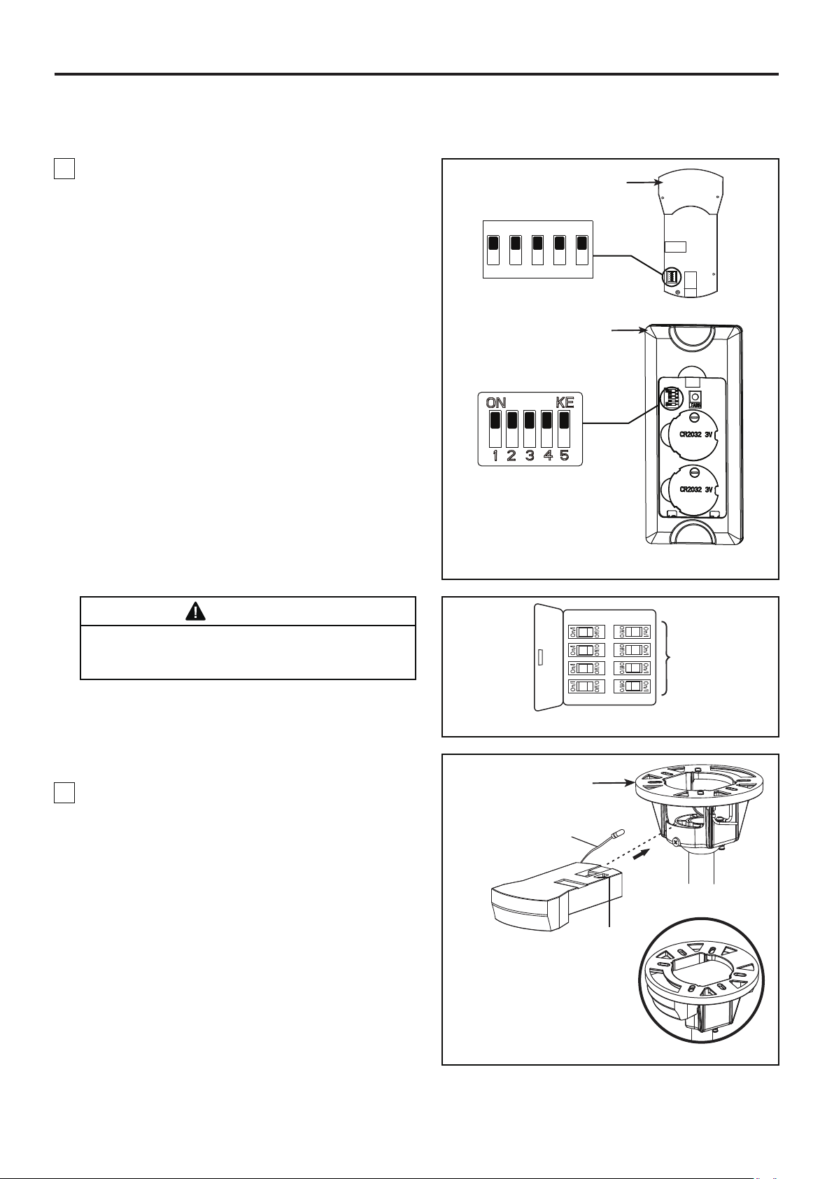
How to Wire Your Ceiling Fan
NOTE: If fan or supply wires are different colors than indicated, have this unit installed by a qualified electrician.
1. To set the code on receiver unit, slide dip switches
to the same positions as set on the remote control.
(Figure 1)
NOTE: The remote unit has 32 different code
combinations. To prevent possible interference from
or to other remote units, simply change the
combination code in the remote and receiver.
Dip Switch
ON
1 2 3 4 5
Receiver
NOTE: Factory setting is all up. Do not use this
position.
WARNING
To avoid possible electrical shock, be sure electricity
is turned off at the main fuse box before wiring.
(Figure 2)
NOTE: If you are not sure if the outlet box is grounded,
contact a licensed electrician for advice, as it must be
grounded for safe operation.
Remote Control
Dip Switch
Figure 1
Main Fuse Box
Figure 2
2. Slide the receiver into the hanger bracket before
wiring as shown in figure 3.
Hanger Bracket
RF Antenna
(Leave connected
and do not cut)
Dip Switch
NOTE: Supply wires
omitted for clarity.
Figure 3
10
Page 11
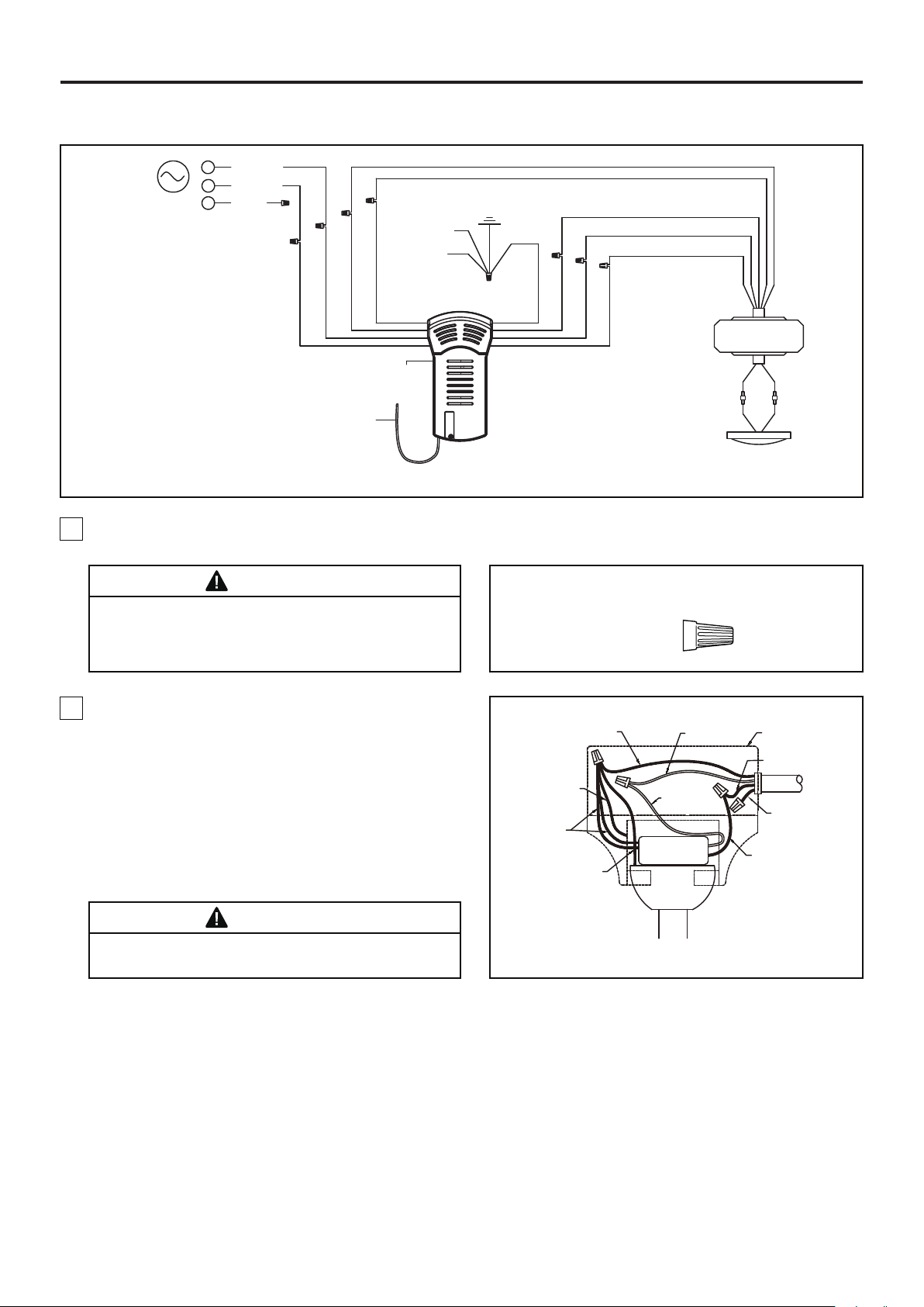
How to Wire Your Ceiling Fan (Continued)
L
BLACK
N
WHITE
L1
AC
POWER
RED
WHITE
RF ANTENNA
BLUE
BLACK
RECEIVER
HANGER
BRACKET
HANGER
BALL
BROWN
3. Connect wires using connectors as shown in
Figure 4.
WARNING
Check to see that all connections are tight, including
ground, and that no bare wire is visible at the wire
connectors. Do not operate fan until the blades are in
place. Noise and motor damage could result.
GROUND
Figure 4
BLUE
BROWN
RED
GRAY
YELLOW
YELLOW /
GREEN (2)
RED
GRAY
YELLOW
DC MOTOR
BLUEWHITE
LIGHT KIT
CAUTION: INCORRECT WIRE CONNECTION
COULD DAMAGE THIS RECEIVER.
RECEIVER HARDWARE USED:
Wire Connectors
X 9
4. After connections have been made, put the white
and green leads to one side and the black leads
towards the other side, the connection should be
turned upward and carefully push leads into the outlet
box. The wires should be spread apart with the
grounded conductor and the equipment-grounding
conductor on one side of the outlet box and the
ungrounded conductor on the other side. (Figure 5)
WARNING
The blades must be installed first before programming
is performed.
Green Wire
from Hanger
Bracket (Ground)
Green Wire
from Receiver (2)
(Ground)
Green Wire
from Hanger
Ball (Ground)
Green Wire
from Supply
(Ground)
White Wire
from Supply
White Wire
from Receiver
Receiver
Figure 5
Listed
Outlet Box
Black Wire
from Supply
Red Wire
from Supply
Black Wire
from Receiver
Household
Supply
11
Page 12
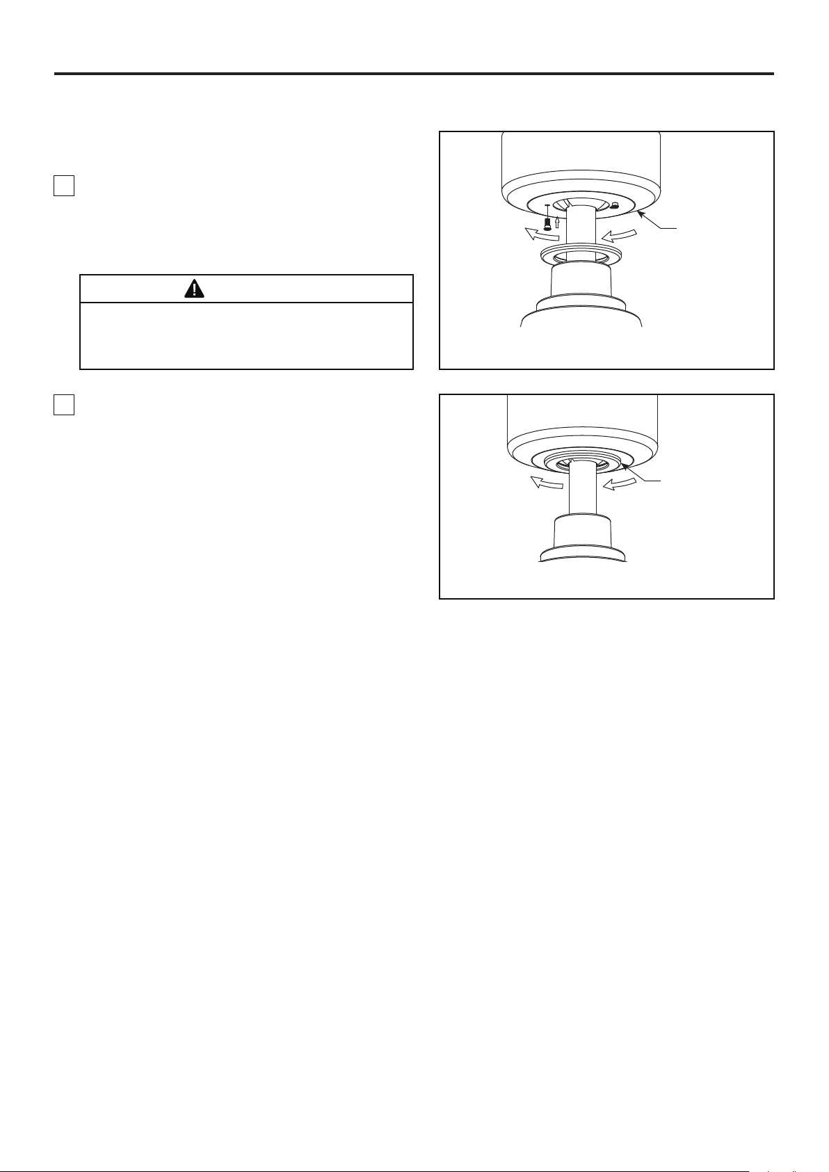
How to Install Your Canopy Housing
NOTE: This step is applicable after the necessary
wiring is completed.
1. Assemble canopy by rotating key slot in canopy
over shoulder screw in hanger bracket, taking care not
to pinch the wires. Tighten shoulder screw. Fully
assemble and tighten second shoulder screw that was
previously removed. (Figure 1)
WARNING
To avoid possible fire or shock, make sure that the
electrical wires are completely inside the canopy
housing and not pinched between the housing and the
ceiling.
2. Securely attach and tighten the canopy screw cover
over the shoulder screws in the hanger bracket
utilizing the key slot twist-lock feature. (Figure 2)
Ceiling Canopy
Figure 1
Canopy Screw
Cover
Figure 2
12
Page 13
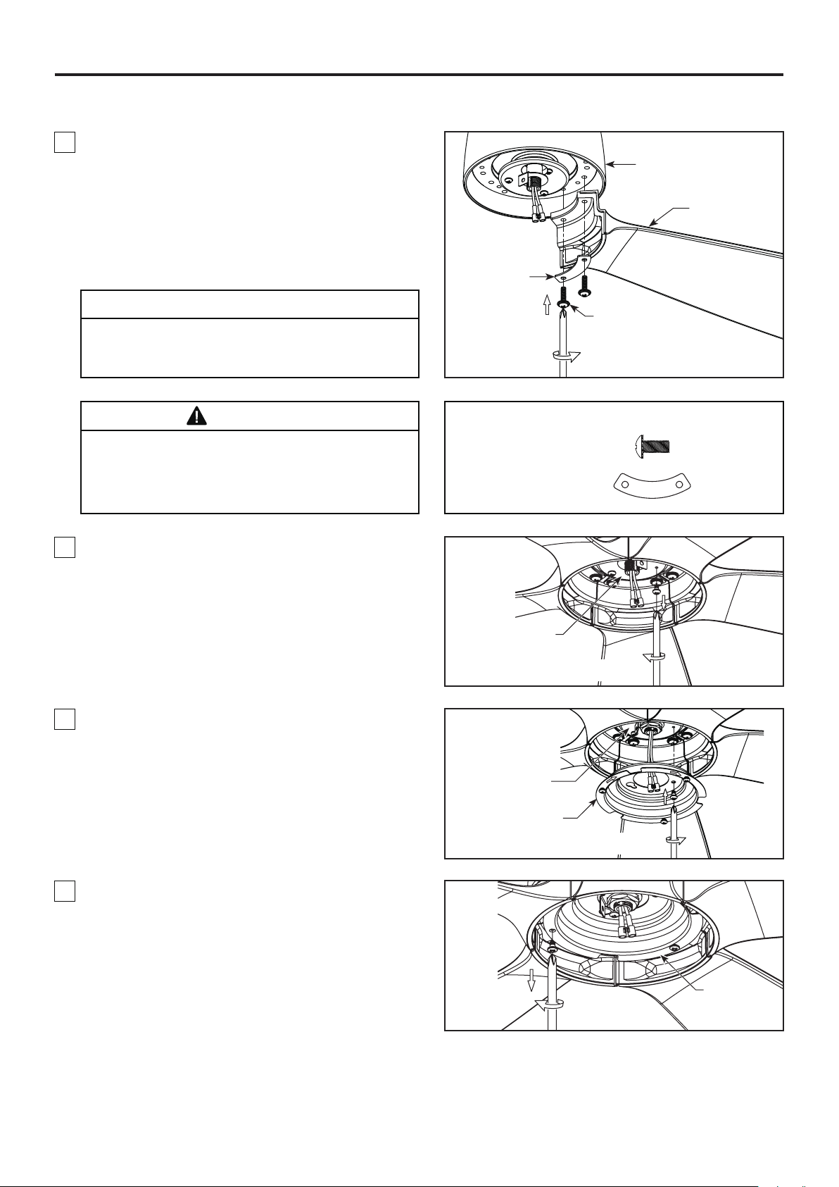
How to Assemble Your Ceiling Fan Blades and Cap
1. Align blade holes with posts on the motor assembly
flywheel. Make sure the blade is fully seated against
the flywheel. Place blade plate over the blade with
holes aligned and assemble blade to flywheel using
serrated head screws, fully tighten the screws that
attach the blades to the motor assembly flywheel.
(Figure 1)
Blade Plate
Motor Assembly
Blade
CAUTION
Do not connect fan blades until the fan is completely
installed. Installing the fan with blades assembled may
result in damage to the fan blades.
WARNING
To reduce the risk of personal injury, do not bend the
blades when installing, balancing or cleaning the fan.
Do not insert foreign objects in between the rotating
blades.
2. Remove one of the three screws in the support
bracket at the bottom of the motor assembly and
retain the screw for later and slightly loosen the
remaining two screws. (Figure 2)
3/16”-24
Serrated Head Screw
Blade Plate
Motor Assembly
3/16˝-24
Serrated Head Screw
(2 each per blade)
Figure 1
HARDWARE USED:
Figure 2
X 10
X 5
3. Assemble the light plate assembly to the support
bracket using the two key slots in the light plate
assembly. Replace the previously removed screw and
securely tighten all three screws. (Figure 3)
4. Remove one of the three screws in the light plate
assembly. Retain the screw for later and slightly
loosen the remaining two screws. (Figure 4)
Motor Assembly
Light Plate
Assembly
Figure 3
Light Plate
Assembly
Figure 4
13
Page 14
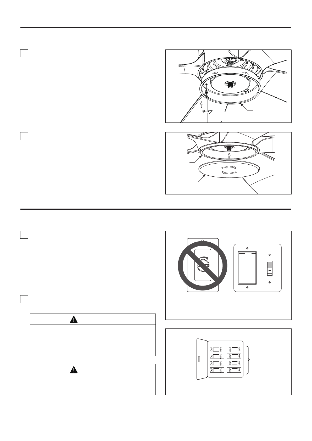
How to Assemble Your Ceiling Fan Blades and Cap (Continued)
5. Assemble the light kit wire cover to the light plate
assembly using the two key slots in the light kit wire
cover. Replace the previously removed screw and
securely tighten all three screws. (Figure 5)
Light Kit
Figure 5
6. Secure the steel cap to light kit wire cover by
twisting in a clockwise direction. Do not over-tighten.
(Figure 6)
Light Kit
Wire Cover
Wire Cover
How to Operate Your Ceiling Fan
1. IMPORTANT: Using a full range dimmer switch (not
included) to control fan speed will damage the fan. To
reduce the risk of fire or electrical shock, do not use a
full range dimmer switch to control the fan speed.
(Figure 1)
2. Restore electrical power to the outlet box by turning
the electricity on at the main fuse box. (Figure 2)
WARNING
Check to see that all connections are tight, including
ground, and that no bare wire is visible at the wire
connectors, except for the ground wire. Do not operate
fan until the blades are in place. Noise and fan
damage could result.
Steel Cap
Figure 6
For illustrative purposes only-not
intended to cover all types of controls
Figure 1
Main Fuse Box
WARNING
Do not operate this fan with a variable (Rheostat) wall
controller or dimmer switch. Doing so could result in
damage to the ceiling fan's remote control unit.
Figure 2
14
Page 15
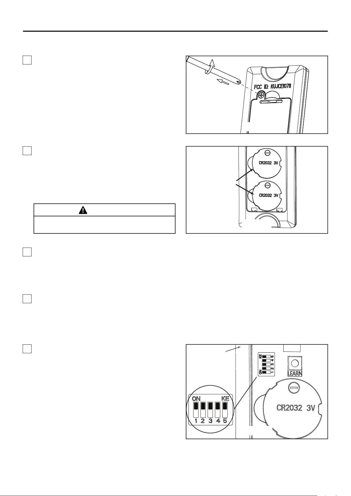
How to Operate Your Ceiling Fan (Continued)
3. Remove the battery cover from remote control by
screwdriver and retain the screw for later. (Figure 3)
4. To make fan operational, install two 3V batteries
(included) in hand-held remote transmitter, with fan
power off. Then, follow the remote code setting
process. If not used for long periods of time, remove
battery to prevent damage to transmitter. Store the
remote away from excessive heat or humidly.
(Figure 4)
WARNING
Figure 3
3V CR2032
Battery (2 pcs)
Chemical Burn Hazard. Keep batteries away from
children.
Figure 4
5. If you have multiple fans and want to program all fans to one handheld control. Slide the Dip Switches to the
same position in ALL receivers as ONE handheld control, then follow Step 1 of the remote control speed set up
process. Each fan needs to be no more than 30 feet from the handheld control that you would like to program.
Please note the wall switch that controls the power to your fan(s) should be in the off position until you are ready
to program your handheld remote(s).
6. If you have multiple fans and want to program each fan to separate handheld controls, slide the Dip Switches
to the same position in both receiver and handheld control, then follow Step 1 of the remote control speed set up
process below for each fan. Repeat these steps for each fan that you would like to program to a separate
handheld remote. Please note that the wall switch that controls the power to your fan(s) should be in the off
position until you are ready to program your handheld remote(s).
7. To set the remote code in the same positions as
the receiver, use a small screwdriver or ball point pen
Remote
Control
(neither included) to slide dip switches firmly up or
down. (Figure 5)
NOTE: Factory setting is all up. Do not use this
Dip Switch
position.
NOTE: The remote unit has 32 different code
combinations. To prevent possible interference from
or to other remote units, simply change the
combination code in the remote and receiver.
Figure 5
15
Page 16
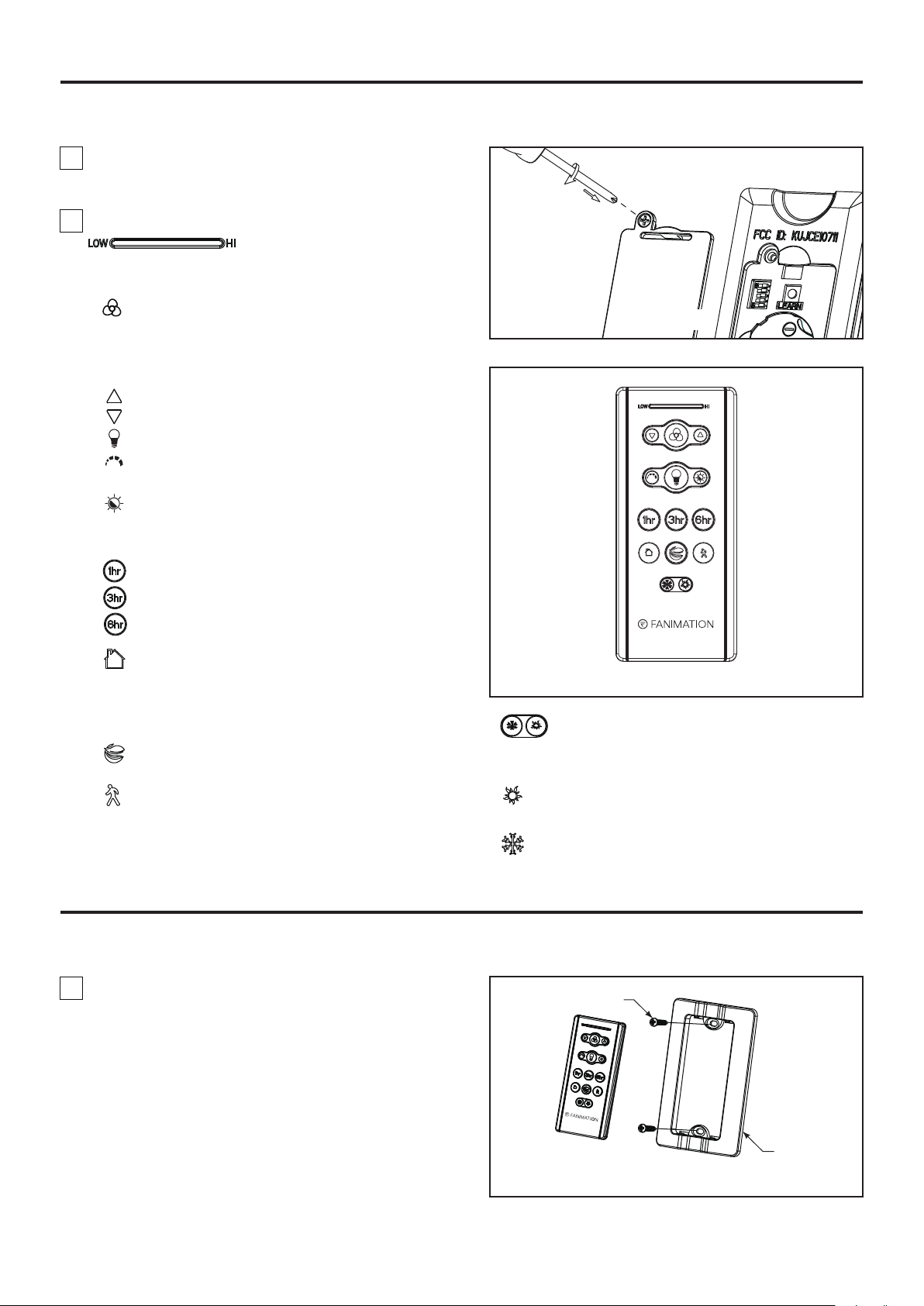
How to Operate Your Ceiling Fan (Continued)
8. Replace battery cover on the remote control and
secure with the previously removed screw. (Figure 6)
9. Remote functions: (Figure 7)
• Indicator LED light: fan speed and light dimmer
indicator
• button: Tap once to turn off the fan. Press and
hold this button for 5 seconds to turn on or turn off
the buzzer.
• Fan Speed:
Turn on fan and turn speed up.
Turn on fan and turn speed down.
• Light button: Turn ON\OFF the light.
Press to turn on the light and hold to dim or
brighten light to desired level, then release.
Press this button to switch color temperature
when the light is on.
• Sleep Timer:
The fan and light will turn off after 1 hour.
Figure 6
The fan and light will turn off after 3 hours.
The fan and light will turn off after 6 hours.
• Home Away: Tap this button, the light will blink
twice signaling this feature is on; the fan will turn off
and the light will randomly turn on and off while you
are away. Pressing any button will cancel the feature.
• Fresh Air: Fan speed will modulate to simulate
a natural breeze.
• Safe Exit: Tap once, the light will blink once; fan
and light will turn off after 1 minute. Pressing any
button will cancel this feature.
How to Install Your Remote Control
1. Installing Wall Plate: (Figure 1)
Attach wall plate using the two provided screws.
Figure 7
• Reverse button:
In order to reverse the direction of the fan, the fan
must be running.
Summer- The fan runs counterclockwise. Airflow
will provide a downward cooling breeze.
Winter- The fan runs clockwise. Airflow will force
warm air downward without a noticeable breeze.
Screws (2)
16
Wall Plate
Figure 1
Page 17
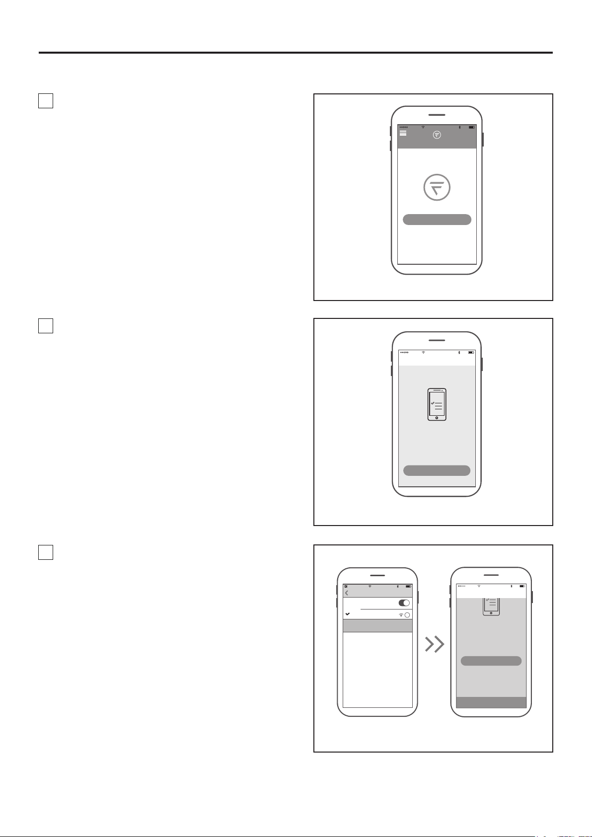
How to Set Up the fanSync WiFi APP
1. Visit the Apple APP Store or the Google Play
Store to download the free fanSync WiFi APP.
Create your Fanimation fanSync account. (Figure 1)
10:37 AM
80%
2. At this stage, your ceiling fan WiFi receiver should
be installed and within range of your WiFi router. With
the APP open, select "add device". (Figure 2)
All
Your dashboard is empty
Add a Fanimation Ceiling Fans
Home
Figure 1
10:37 AM
Add Fainmation..
Connect To Your Dvice
WI-FI
80%
NOTE: The device default WiFi SSID :
Fanimation_XXXXXX (ex: Fanimation_402AD4).
3. Select the Fanimation_XXXXXX device and back to
fanSync WiFi APP and press "CONTINUE". (Figure 3)
10:38 AM
fanSync W...
Settings
Wi-Fi
Wi-FI
Fanimation_402AD4
Unsecured Network
CHOOSE A NETWORK
To begin you must first connect your phone
to the Fanimation Ceiling Fans you are
setting up. Your Fanimation Ceiling Fans will
broadcast a temporary Wi-Fi hotspot that
looks like
“Fanimation_xxxxxx”.
Go to Settings
Once you’ve completed this step come back
Figure 2
80%
i
To begin you must first connect your phone
setting up. Your Fanimation Ceiling Fans will
broadcast a temporary Wi-Fi hotspot that
Once you’ve completed this step, come back
10:39 AM
Add Fainmation..
to the Fanimation Ceiling Fans you are
looks like
“Fanimation_xxxxxx”.
Go to Settings
to the fanSync WiFi app to continue the
setup.
CONTINUE
80%
17
Figure 3
Page 18
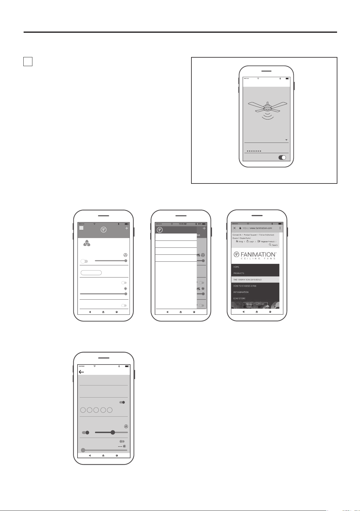
How to Set Up the fanSync WiFi APP (Continued)
4. Select your WiFi router and enter the WiFi
password to connect your fanSync WiFi receiver.
It will take 1-2 minutes to connect. After your WiFi
receiver is connected, you can now name your ceiling
fan in the APP and customize your settings. (Figure 4)
● fanSync WiFi APP Overview
10:40 AM
Add Fainmation..
Set Up Wi-Fi Network
Enter your network settings below to
connect your device online.
SSID
XXXXX
PASSWORD
Remember my SSID and pa...
Figure 4
80%
10:40 AM
All
Lounge
OFF 100%
BREEZE MODE
NORMAL
LIGHT
HOME AWAY
FRESH AIR
● Set up Real Time Schedule
10:43 AM
Edit Schedule
SCHEDULE NAME
Work Days
START TIME END TIME
8:00 PM 5:00 PM
REPEAT
M T W TH F SA SU
ON
Home
OFF
100%
OFF
80%
HOME
MY GROUP
SETTINGS
SUPPORT
80%
10:42 AM
80%
ON
Settings
51 %
OFFLIGHT
18
Page 19
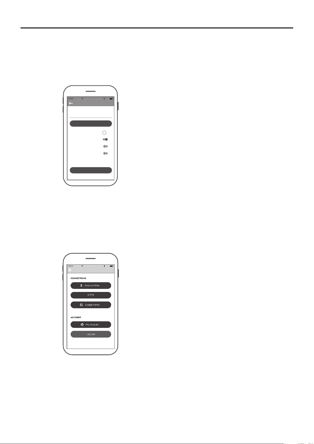
How to Set Up the fanSync WiFi APP (Continued)
● Share Device
After one smart device is connected to a fan, you
must share the device with other users in order to
control the fan with their device's APP.
10:45 AM
Settings
DEVICE NAME
Lounge
Save
EXTRA DEVICE CONTROLS !
HIDE FAN DIRECTION
HIDE LIGHT POWER
HIDE LIGHT DIMMER
FAMILY SHARING
SHARE DEVICE
80%
● Link with Amazon Echo, Google Home and IFTTT
Select the device you want to connect and follow the instructions in the set up procedure.
Amazon Alexa Help:https://www.amazon.com/gp/help/customer/display.html?nodeId=201749240
In order to connect with NEST, ECOBEE, Samsung Smart things, wink, etc. that you must connect via IFTTT.
IFTTT Help: https://help.ifttt.com/hc/en-us/articles/115010325748-What-is-IFTTTGoogle Help: https://support.google.com/googlehome/answer/7073578?hl=en
10:46 AM
Settings
80%
19
Page 20
Maintenance
Periodic cleaning of your new ceiling fan is the only
maintenance necessary.
When cleaning, use only a soft brush or lint free cloth to
avoid scratching the finish.
Abrasive cleaning agents are not required and should be
avoided to prevent damage to finish.
How to Clean Your Ceiling Fan Blades
Periodic light dusting of the blades is recommended.
A feather duster will work best.
Troubleshooting
WARNING
For your own safety turn off power at fuse box or circuit breaker before trouble shooting your fan.
Trouble Probable Cause Suggested Remedy
CAUTION
Do not use solvents when cleaning your ceiling fan. It
could damage the motor or the blades and create the
possibility of electrical shock.
Avoid using water, cleansers, or harsh rags, which
can warp and ruin the blades.
1. FAN WILL NOT START.
2. FAN SOUNDS NOISY.
3. FAN WOBBLES
EXCESSIVELY.
4. REMOTE CONTROL
DOES NOT WORK. THE
CONTROL INDICATOR LED
IS CONSTANTLY
FLASHING.
1. Fuse or circuit breaker blown.
2. Loose power line connections to the fan, or loose
switch wire connections in the switch housing.
3. Dead battery in remote control.
1. Blades not attached to fan.
2. Loose screws in motor housing.
3. Screws securing fan blade to motor assembly are
loose.
4. Lower housing support set screw loose.
1. Setscrew in downrod support is loose.
2. Setscrew in downrod/hanger ball assembly is loose.
3. Screws securing fan blade to motor assembly are
loose.
4. Hanger bracket and/or ceiling outlet box is not
securely fastened.
1. Check main and branch circuit fuses or circuit
breakers.
2. Check line wire connections to fan and switch wire
connections in the switch housings.
CAUTION: Make sure main power is turned off !
3. Replace with fresh battery.
1. Attach blades to fan before operating.
2. Check to make sure all screws in motor housing are
snug (not over-tight).
3. Check to make sure the screws which attach the fan
blade to the motor assembly are tight.
CAUTION: Make sure main power is turned off !
4. Tighten set screw securely.
1. Tighten both setscrews securely in downrod support.
2. Tighten the setscrew in the downrod/hanger ball
assembly.
3. Check to be sure screws which attach the fan blade
to the motor assembly are tight.
4. Tighten the hanger bracket screws to the outlet box,
and secure outlet box.
1. Please replace the battery/batteries.1. The battery/batteries are going to run out.
5. NOT ENOUGH AIR
MOVEMENT.
1. If possible, consider using a longer downrod (not
included, you can buy the longer downrod from
fanimation.com).
20
Page 21
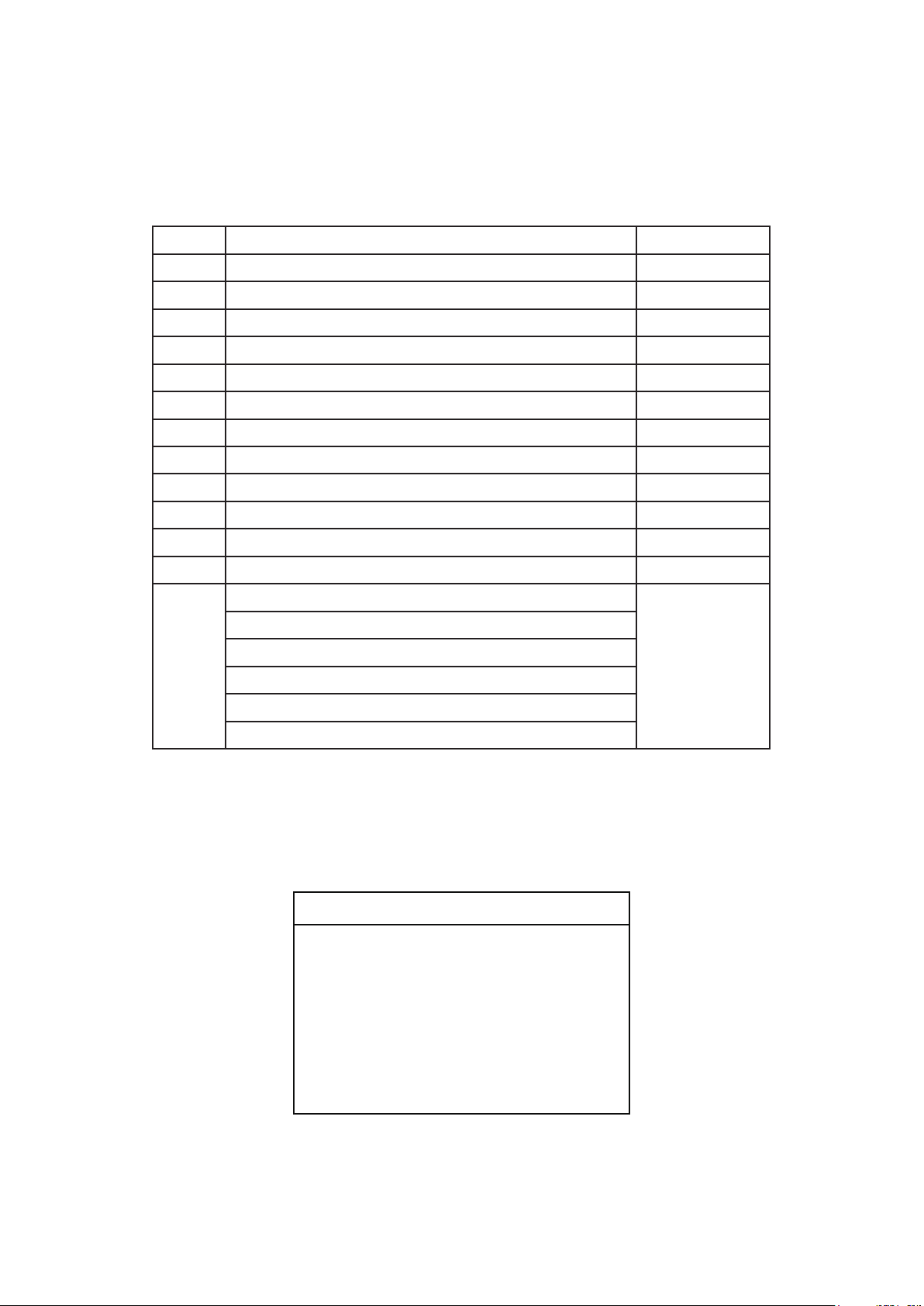
Parts List
Model #FPD5534**
Ref. # Description Part #
1
Hanger Bracket Assembly
AP255BL
10
11
12
13
2
3
4
5
6
7
8
9
Hanger Ball / Downrod Assembly
Ceiling Canopy
Canopy Screw Cover Assembly
Motor Coupling Cover Assembly
Motor Assembly
Blade Set AP553405**
Light Plate Assembly AP853407BL
Light Kit Wire Cover Assembly AP853413BL
Steel Cap P853414**
Receiver
Hand-held Remote
Hardware Bags Containing:
Safety Cable Kit
Wire Connectors (4)
Blade Mounting Hardware Bags Containing:
3/16˝-24 Serrated Head Screws (11)
Blade Plates (5)
ADR1-45**
P853401**
AP260**
AP853404**
AMA5534**
WFRCCD553400
TR305
HDWFPD5534**
** Insert FINISH CODES (Refer to fan model number located on downrod support)
Before discarding packaging materials, be certain all parts have been removed.
How To Order Parts
When ordering repair parts, always give the
following information:
• Fan Model Number
• Part Number
• Part Description
• Date Code
Contact [email protected] or
call 1.888.567.2055 for repair parts.
21
Page 22
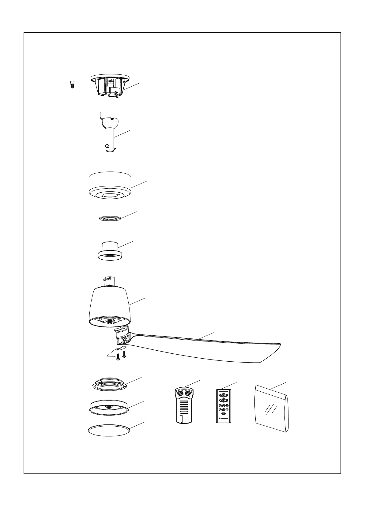
™
KUTE5
52
Model FPD5534**
Exploded-View Illustration
13
2
1
3
4
13
5
6
7
8
11
12
13
9
10
NOTE: The illustration shown is not to scale or its actual configuration may vary.
Product/parts are subject to change without notice.
22
Page 23
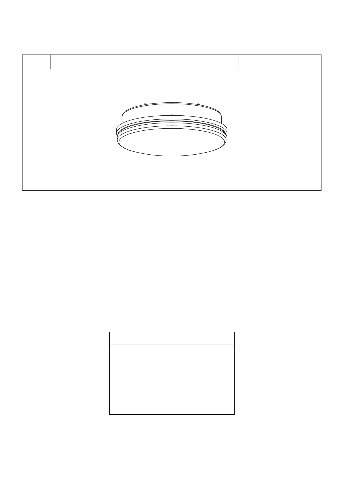
Optional Light Kit
Light Kit Assembly1 LK8534**
NOTE: The illustration shown is not to scale or its actual configuration may vary.
Before discarding packaging materials, be certain all parts have been removed.
How To Order Parts
When ordering repair parts, always give the
following information:
• Fan Model Number
• Part Number
• Part Description
• Date Code
Contact [email protected] or
call 1.888.567.2055 for repair parts.
23
Page 24

10983 Bennett Parkway
Zionsville, IN 46077
Phone: 888-567-2055
Outside U.S.: 317-733-4113
FAX: 866-482-5215
FANIMATION.COM
2022/03 V.01
Copyright 2022 Fanimation
Page 25
VENTILADOR DE TECHO KUTE5 ™ 52
MODELO #FPD5534**
ADJUNTE SU RECIBO AQUÍ Y REGISTRE SU VENTILADOR EN FANIMATION.COM
LEA Y GUARDE ESTAS INSTRUCCIONES
Código de fecha
Para ofrecer un servicio rápido y de calidad, por favor suministre el código de fecha. Puede
encontrar el código de fecha en el paquete, en el mando a distancia (dentro del compartimento de
las pilas), en el receptor o en la parte superior de la carcasa del ventilador.
Preguntas, problemas, piezas faltantes? Antes de volver a la tienda, llame a nuestro
Departamento de Servicio al Cliente al 1-888-567-2055, 8 a.m. - 5 pm, hora del Este, de
lunes - viernes.
Fecha de compra
Peso neto 5.30 kgs (11.69 lbs)
Page 26
Instrucciones de seguridad importantes
ADVERTENCIA: Siga estas instrucciones para prevenir incendios, descargas eléctricas y lesiones personales graves.
AVERTISSEMENT: Suivez ces instructions pour éviter un incendie, une électrocution et des blessures graves.
1. Lea el manual del propietario y la información de seguridad antes de instalar su nuevo ventilador. Observe los diagramas de ensamblaje adjuntos.
2. Antes de llevar a cabo el mantenimiento o la limpieza de la unidad, desconecte la electricidad en el panel de servicio y bloquee los medios de
desconexión del mismo para evitar que se active accidentalmente. Si no se pueden bloquear los medios de desconexión del servicio, coloque un
dispositivo de advertencia, como una etiqueta, en el panel de servicio.
3. Tenga cuidado con la estructura y las aspas del ventilador cuando limpie, pinte o trabaje cerca del mismo. Desconecte siempre la electricidad del
ventilador de techo antes de llevar a cabo el mantenimiento.
4. No coloque nada en las aspas del ventilador cuando éste se encuentra en funcionamiento.
5. El dispositivo no ha sido diseñador para ser utilizado por niños o personas enfermas sin supervisión. Los niños deben ser supervisados para
asegurarse de que no juegan con el dispositivo.
Instrucciones de seguridad adicionales
1. Para evitar posibles descargas eléctricas, asegúrese de que la electricidad esté desconectada en la caja de fusibles antes de realizar la
instalación eléctrica, y no haga funcionar el ventilador sin las aspas.
2. Todos los procedimientos de conexión eléctrica e instalación deben cumplir con los Códigos eléctricos nacionales (ANSI/NFPA 70) y Códigos
locales. El ventilador de techo debe estar conectado a tierra a fin de prevenir posibles descargas eléctricas. La instalación eléctrica debe ser
llevada a cabo o aprobada por un electricista autorizado.
3. Se debe fijar bien la base del ventilador; ésta debe ser capaz de soportar sin problemas al menos 15,9 kg (35 lb). Consulte la página 29 del
manual del propietario para ver los requisitos de soporte. Si tiene dudas, consulte a un electricista calificado.
4. Las aspas del ventilador deben instalarse por lo menos a 2,13 m (7 pies) del suelo, a fin de evitar un contacto accidental con las mismas.
5. Siga las recomendaciones sobre el método correcto de instalación eléctrica de su ventilador de techo. Si no posee la experiencia o los
conocimientos eléctricos adecuados, contrate a un electricista autorizado para instalar el ventilador.
6. Apto para usar con controles de velocidad de estado sólido.
7. Este ventilador es ideal para lugares secos y húmedos.
8. Use solo con los kits de luz marcados como adecuados para usar lugares secos y húmedos.
9. En lo que respecta a las conexiones de suministro, si el conductor del ventilador está identificado como conductor con conexión a tierra, se le debe
conectar a un suministro de electricidad con conductor de puesta a tierra. Si el conductor del ventilador está identificado como conductor que no es
de puesta a tierra, se le debe conectar a un suministro de electricidad con conductor sin puesta a tierra. Si el conductor del ventilador está
identificado para equipos de puesta a tierra, se le debe conectar al conductor de equipos de puesta a tierra.
10. El mando a distancia de este producto contiene pilas de botón/plana de litio. Si la pila de botón/plana de litio nueva o usada se ingiere o entrase en
el cuerpo humano, puede causar severas quemaduras internas y puede causar la muerte en tan solo 2 horas. Asegure siempre por completo el
compartimento de la pila. Si el compartimento de la pila no está cerrado de forma segura, deje de utilizar el mando a distancia del producto, extraiga
las pilas y manténgalo alejado del alcance de los niños. Si piensa que las pilas pueden haber sido tragadas o colocadas dentro de cualquier parte
del cuerpo humano, busque asistencia médica inmediatamente.
- Las pilas planas deben ser desechadas adecuadamente, y siempre debe estar fuera del alcance de los niños.
- Las pilas planas también pueden causar heridas.
11. Apagar el control de pared puede anular cualquier dispositivo inteligente habilitado o comandos de control remoto.
ADVERTENCIA: Peligro de quemadura química. Mantenga las pilas lejos del alcance de los niños.
ADVERTENCIA: PARA REDUCIR EL RIESGO DE DESCARGAS ELÉCTRICAS, ESTE VENTILADOR SE DEBE INSTALAR CON UN CONTROL/
INTERRUPTOR DE PARED AISLADO.
ADVERTENCIA: Este producto está diseñado para ser usado sólo con las piezas suministradas o los accesorios indicados específicamente para el
mismo. Si utiliza piezas o accesorios que no están indicados para su uso con este producto, podría sufrir lesiones personales o
dañar el ventilador.
ADVERTENCIA: Para reducir el riesgo de lesiones personales, no doble los de las aspas al instalar aspas del ventilador, balancear las aspas o
limpiar el ventilador. No coloque objetos extraños entre las aspas del ventilador en funcionamiento.
ADVERTENCIA: No utilice este ventilador con un controlador variable de pared (Rheostat) o un regulador de intensidad. Si lo hiciera podría dañar la
unidad del mando a distancia del ventilador de techo.
ADVERTENCIA: Monte a una caja de salida aceptable para apoyo de los aficionados de 15,9 kg (35 lbs) o menos.
AVERTISSEMENT: Risque de brûlure chimique. Gardez les piles hors de portée des enfants.
AVERTISSEMENT: CE VENTILATEUR DOIT ÊTRE INSTALLÉ AVEC UNE COMMANDE/INTERRUPTEUR MURAL ISOLANT À USAGE GÉNÉRAL
AFIN DE RÉDUIRE LES RISQUES D'ÉLECTROCUTION.
AVERTISSEMENT: Ce produit est conçu pour utiliser uniquement les pièces l'accompagnant et/ou les accessoires spécifiquement conçus pour ce
produit. L'utilisation de pièces et/ou d'accessoires qui ne sont pas conçus pour être utilisés avec ce produit peut provoquer des
blessures ou des dommages matériels.
AVERTISSEMENT: Afin de réduire le risque de blessure, ne pliez pas la pale lors de l'installation des pales, de l'équilibrage des pales ou du nettoyage
du ventilateur. N'insérez pas de corps étrangers entre les pales du ventilateur en rotation.
AVERTISSEMENT: N'utilisez pas ce ventilateur avec un contrôleur mural (rhéostat) variable ou un gradateur. Cela pourrait endommager la
télécommande du ventilateur de plafond.
AVERTISSEMENT: Montez sur une boîte de sortie indiquée comme étant acceptable.
(1) Este equipo no causará interferencias perjudiciales y (2) este equipo tolerará cualquier interferencia recibida, incluidas las interferencias
que puedan provocar un funcionamiento no deseado. Si el radiador intencional puede ser clasificado como un dispositivo digital de clase B
o un periférico del ordenador, entonces se deberán incluir los siguientes o equivalentes:
Nota: Tras someterlo a las pruebas correspondientes, se ha determinado que este equipo cumple con los límites establecidos para
dispositivos digitales de Clase B de conformidad con la parte 15 de la Normativa FCC. Estos límites se han establecido con el objetivo de
aportar una protección razonable contra interferencias perjudiciales cuando el equipo se utiliza en el hogar. Este equipo genera, utiliza y
puede emitir energía de radiofrecuencia y, a menos que se instale y se utilice de acuerdo con el manual de instrucciones, puede
provocar interferencias perjudiciales en las comunicaciones por radio y televisión. Si el equipo produce interferencias perjudiciales en la
recepción de radio o televisión, lo cual puede probarse encendiendo y apagando el equipo, se recomienda al usuario corregir dichas
interferencias tomando una o varias de las siguientes medidas:
- Modificar la orientación o ubicación de la antena de recepción;
- Aumentar la separación entre el equipo y el receptor;
- Conectar el equipo a una toma de corriente o circuito diferente al del receptor;
Consulte al distribuidor o a un técnico especialista de radio o TV para obtener más ayuda.
Page 27
Se extiende al comprador original del ventilador Fanimation solo desde un distribuidor/minorista autorizado de Fanimation
GARANTÍA LIMITADA DE POR VIDA
1. GARANTÍA LIMITADA DE POR VIDA DEL MOTOR - Si se produjera una falla en alguna de las partes del motor de su ventilador debido
a un defecto en los materiales o en la fabricación durante el tiempo de vida del comprador original, Fanimation proporcionará la pieza de
repuesto sin cargo una vez que el ventilador defectuoso sea devuelto a nuestro centro de servicios nacional. Se requiere comprobante de
venta. El cliente se hará responsable de todos los gastos de remoción o reinstalación y envío del producto para reparaciones o sustitución.
2. GARANTÍA DE MANO DE OBRA DEL MOTOR POR UN AÑO - Si el motor de su ventilador fallara antes de cumplirse un año a partir del
momento de su compra original debido a defectos en los materiales o en la fabricación, se le efectuará la reparación del mismo sin cargo
en nuestro centro de servicios nacional. El comprador se hará responsable de los gastos de mano de obra luego del período de un año.
El cliente se hará responsable de todos los gastos de remoción o reinstalación y envío del producto para reparaciones o sustitución.
3. Si otra pieza del ventilador fallara dentro del período de un año a partir de la fecha de compra original debido a un defecto en los
materiales o en la fabricación, repararemos o sustituiremos, según creamos conveniente, la pieza defectuosa sin cargo alguno en
nuestro centro de servicios nacional.
4. Debido a las diversas condiciones climáticas, esta garantía no cubre cambios en la terminación, incluidos oxidación, corrosión,
falta de brillo o peladuras.
5. Esta garantía es nula y no se aplica a daños por instalación incorrecta, negligencia, accidentes, uso indebido, exposición al calor o
a la humedad en exceso, o como resultado de cualquier modificación realizada al producto original.
6. Todos los gastos de remoción y reinstalación del ventilador son responsabilidad exclusiva del propietario, y no de la tienda que
vendió el ventilador ni de Fanimation.
7. Fanimation se reserva el derecho de modificar o discontinuar un producto en cualquier momento, o sustituir cualquier pieza según
lo establecido por esta garantía.
8. En ningún caso se podrá devolver un ventilador sin previa autorización por parte de Fanimation. Las devoluciones autorizadas
deberán ir acompañadas del recibo de venta y deberán enviarse a Fanimation, previo pago del flete. El ventilador que se devuelva
deberá estar embalado en forma adecuada a fin de evitar daños durante el transporte. Fanimation no se hará responsable de los
daños que resulten del embalaje incorrecto del producto.
9. Se entiende que las reparaciones y las sustituciones son el único recurso disponible de Fanimation. No existe ninguna otra
garantía expresa o implícita. Por la presente, Fanimation niega todas las garantías implícitas, que incluyen, entre otras, la
comerciabilidad y la aptitud para determinado fin hasta donde la ley lo permita. Algunos estados no permiten limitaciones sobre las
garantías implícitas. Fanimation no se hará responsable por daños accidentales, resultantes o especiales derivados del uso o el
rendimiento del producto o en conjunción con éste, excepto en los casos en los que la ley así lo disponga. Esta garantía le otorga
derechos legales especiales y es posible que también goce de otros derechos que pueden variar según el estado.
10. Es normal que se produzca un cierto movimiento oscilante y esto no debe considerarse un problema o defecto.
Tabla de contenidos
Instrucciones para el desempaque . . . . . . . . . . . . . . . . . . . . . . . . . . . . .
Uso eficiente de la energía en ventiladores de techo . . . . . . . . . . . . . .
Requisitos eléctricos y estructurales . . . . . . . . . . . . . . . . . . . . . . . . . . .
Cómo ensamblar el ventilador de techo . . . . . . . . . . . . . . . . . . . . . . . . .
Cómo colgar el ventilador de techo . . . . . . . . . . . . . . . . . . . . . . . . . . . . .
Cómo realizar la instalación eléctrica del ventilador de techo . . . . . . .
Cómo instalar la carcasa de la cubierta . . . . . . . . . . . . . . . . . . . . . . . . .
Cómo ensamblar las aspas del ventilador de techo y la tapa . . . . . . . .
Cómo utilizar su ventilador de techo . . . . . . . . . . . . . . . . . . . . . . . . . . . .
28
29
29
31
33
35
37
38
40
Cómo instalar su mando a distancia . . . . . . . . . . . . . . . . . . . . . . . . . . . .
Configuración de la App fanSync WiFi . . . . . . . . . . . . . . . . . . . . . . . . . .
Mantenimiento . . . . . . . . . . . . . . . . . . . . . . . . . . . . . . . . . . . . . . . . . . . . . .
Limpieza de las aspas . . . . . . . . . . . . . . . . . . . . . . . . . . . . . . . . . . . . . . . .
Solución de problemas . . . . . . . . . . . . . . . . . . . . . . . . . . . . . . . . . . . . . . .
Lista de piezas . . . . . . . . . . . . . . . . . . . . . . . . . . . . . . . . . . . . . . . . . . . . . .
Ilustración del despiece . . . . . . . . . . . . . . . . . . . . . . . . . . . . . . . . . . . . . . .
Kit de iluminación opcional . . . . . . . . . . . . . . . . . . . . . . . . . . . . . . . . . . . .
Este manual está diseñado para facilitar, en la medida de lo posible, el ensamblaje,
la instalación, el funcionamiento y el mantenimiento de su ventilador de techo
MaterialesHerramientas necesarias para el ensamblaje
(No incluido)
• Destornillador Phillips
• Escalera de tijera
ADVERTENCIA
Antes de ensamblar el ventilador de techo, consulte la
sección sobre el método correcto de instalación eléctrica
del ventilador (página 35). Si siente que no posee la
experiencia o los conocimientos eléctricos necesarios,
contrate a un electricista autorizado para instalar el
ventilador.
NOTA: coloque las piezas de las bolsas de piezas individuales
en un contenedor pequeño para evitar que se extravíen. Si
faltan piezas, póngase en contacto con su proveedor local.
• Destornillador de ¼˝
• Pelacables
La caja de distribución eléctrica y los conectores de la caja
deben ser del tipo requerido por el código local. El cable
más pequeño debe ser un cable de tres conductores (de dos
conductores con conexión a tierra) del siguiente tamaño:
longitud del cable instalado tamaño del cable según el A.W.G.
hasta 15,2 m (50 pies) de
15,2 a 30,5 m (50 a 100 pies)
AVERTISSEMENT
Reportez-vous à la section sur la méthode appropriée
de câblage du ventilateur (page 35) avant d'assembler
votre ventilateur de plafond. Faites installer votre
ventilateur par un électricien agréé si vous pensez que
vous n'avez pas assez de connaissances ou d'expérience
en câblage.
(Calibre de Alambre Estadounidense)
14
12
43
44
47
47
48
49
50
51
Page 28
Instrucciones para el desempaque
Para su comodidad, marque cada uno de los pasos. A medida que completa cada paso, coloque una marca de verificación.
Con esto se asegurará de completar todos los pasos y podrá saber desde dónde retomar si fuera interrumpido.
ADVERTENCIA
AVERTISSEMENT
No instale ni utilice el ventilador si falta alguna pieza o si
hay piezas dañadas. Este producto está diseñado para ser
utilizado sólo con las piezas suministradas o los
accesorios indicados por Fanimation específicamente
para el mismo. La sustitución de piezas o accesorios que
Fanimation no designó para usar con este producto
podría ocasionar lesiones personales o daños en el
ventilador. Póngase en contacto con su tienda si faltan
piezas o hay piezas dañadas.
1. Verifique que haya recibido las siguientes piezas:
NOTA: Si no está seguro de la descripción de una
pieza, consulte la ilustración del despiece.
Unidad del soporte
de suspensión (1)
Capuchón de techo (1)
Unidad del motor (1)
Cubierta para el
tornillo del capuchón (1)
N'i nstallez pas et n'utilisez pas le ventilateur si l'une de
ses pièces est endommagée ou manquante. Ce produit
est conçu pour utiliser uniquement les pièces l'accompagnant et/ou les accessoires spécifiquement conçus pour ce
produit par Fanimation. La substitution de pièces ou
d'accessoires non conçus par Fanimation pour être
utilisés avec ce produit peut provoquer des bless-ures ou
des dommages matériels. Contactez votre lieu de vente en
cas de pièces manquantes ou endommagées.
Cubierta del cable del
kit de iluminación (1)
Mano a distancia (1)
Placa de la pared (1)
Tornillos (2)
Baterías (2)
Tapa de acero (1)
Receptor (1)
Conectores de cables (9)
Unidad del barral/
de la semiesfera (1)
– Varilla (1)
– Bola colgante (1)
– Tornillo de fijación (1)
– Clip de horquilla (1)
– Pasador de horquilla (1)
– Pasador (1)
Bolsas de accesorios Kit de cable de seguridad
3/16”-24 tornillos de
cabeza dentada
(11)
Cubierta de
unión del motor (1)
Placa de pala
(5)
Ensamble de la placa
de iluminación (1)
Conectores de cables
(4)
Juego de aspas (1)
Cable de soporte
(1)
Abrazadera del
cable de soporte
(1)
Arandela plana,
acero inoxidable
(1)
Tornillo de
intervalo
(1)
28
Page 29
Uso eficiente de la energía en ventiladores de techo
El nivel de rendimiento y ahorro de energía de los
ventiladores de techo dependen de su correcta
instalación y uso. Acontinuación le presentamos
algunas sugerencias para asegurar un rendimiento
eficiente del producto.
Selección del lugar de montaje adecuado
Los ventiladores de techo se deben instalar en el centro
de la habitación, a 2,13 m (7 pies) de altura del piso hasta
la cuchilla como mínimo y 0,5 m (18 pulgadas) de las
paredes hasta la cuchilla. Si la altura del techo lo permite,
instale el ventilador a 2,5 m (8 - 9 pies) de altura del piso
hasta la cuchilla para un flujo de aire óptimo. Consulte en
su tienda minorista de Fanimation para obtener accesorios
de montaje opcionales.
Apague el ventilador cuando no se encuentre en la
habitación
Los ventiladores son para refrescar a la gente, no a
las habitaciones. Si la habitación está vacía, apague el
ventilador de techo para ahorrar energía.
Requisitos eléctricos y estructurales
Uso del ventilador de techo todo el año
En verano: Use el ventilador de techo en sentido
contrario a las agujas del reloj. El flujo de aire que
produce el ventilador creará un efecto frío del aire que
lo refrescará más. Seleccione una velocidad que le
proporcione una brisa confortable. Las velocidades
más bajas consumen menos energía.
En invierno: Invierta el motor y haga funcionar el
ventilador de techo a velocidad baja y en el sentido de
las agujas del reloj. Esto produce una suave corriente
ascendente, que obliga al aire cálido que se acumula
cerca del techo a bajar al espacio ocupado. No olvide
ajustar el termostato cuando utilice el ventilador de
techo. Con este sencillo paso puede ahorrar energía
adicional y dinero.
Su nuevo ventilador de techo requiere una línea de
suministro eléctrico con conexión a tierra de 120 voltios de
CA, 60 Hz, circuito de 15 amperios. La normativa eléctrica
requiere el uso de una caja de distribución eléctrica para
ventiladores que soporte el peso extra y el movimiento
asociado a un ventilador de techo. La caja de distribución
eléctrica será etiquetada como tal y soportará un
ventilador de techo de un peso de hasta 70 libras. Dichas
cajas varían en tipos y diseños. Asegúrese d que el tipo
de su caja reúne los criterios para el ventilador que se
está instalando. Las ilustraciones 1, 2 y 3 muestran las
diferentes configuraciones estructurales que pueden ser
utilizadas para dicha caja de distribución eléctrica.
Uso de perfil bajo (Figura 1)
La caja lisa de 1/2 pulgada de profundidad será atornillada
a una viga o bloque. Se utilizará si solo un cable va a ser
introducido en la caja. También está disponible en una
configuración de montaje endosado.
Uso de perfil profundo (Figura 2)
La caja de 2-1/4 pulgada será atornillada a un bloque
entre vigas que tenga suficiente espacio para colocar más
de un cable.
Techo
Vigas del techo
2" x 4"
Caja de distribución
eléctrica
Figura 1
Vigas del techo
2" x 4"
29
Techo
Figura 2
Caja de distribución
eléctrica
Page 30
Requisitos eléctricos y estructurales (cont.)
Uso del soporte (Figura 3)
Conectado a una caja de distribución eléctrica, este
colgador sirve para abarcar el espacio entre dos vigas y
ocupar el lugar de bloqueo de la madera.
ADVERTENCIA
Para reducir el riesgo de incendios, descargas eléctricas
o lesiones personales, fije el ventilador a la caja de
distribución eléctrica marcada como aceptable para soporte
de ventilador de 15,88kg (35lb). Utilice los tornillos
suministrados con la caja de distribución eléctrica. La
mayoría de las cajas de distribución eléctricas que
comúnmente se utilizan como soporte de lámparas no son
aptas para soporte de ventiladores y es posible que deban
reemplazarse. Consulte a un electricista calificado si tiene
dudas.
AVERTISSEMENT
Pour réduire le risque d'incendie, d'électrocution ou de
blessure, montez sur une boîte de sortie indiquée comme
étant acceptable pour supporter un ventilateur. La plupart
des boîtes de sortie communément utilisées pour supporter
les luminaires ne sont pas acceptables pour supporter des
ventilateurs et devraient être remplacées. Consultez un
électricien qualifié en cas de doutes.
Si su ventilador va a sustituir una instalación de
iluminación existente, desconecte la electricidad de la caja
del fusible principal en esta ocasión y extraiga la unidad
de iluminación.
Vigas del techo
Techo
Caja de
distribución
Figura 3
ADVERTENCIA
A fin de evitar incendios o descargas eléctricas, siga
con cuidado todas las instrucciones de instalación
eléctrica. Cualquier trabajo eléctrico que no se describa
en estas instrucciones deberá ser realizado o aprobado
por un electricista autorizado.
AVERTISSEMENT
Respectez attentivement toutes les instructions de
câblage pour éviter tout incendie ou électrocution.
Tout travail électrique non décrit dans ces instructions
doit être fait ou approuvé par un électricien agréé.
eléctrica
ADVERTENCIA
Apagar el interruptor de pared no es suficiente. Para evitar
posibles descargas eléctricas, asegúrese de que la
electricidad esté desconectada en la caja de fusibles
principal antes de realizar la instalación eléctrica. Toda
instalación eléctrica debe cumplir con los códigos
nacionales y locales y el ventilador de techo debe tener la
conexión a tierra adecuada como forma de precaución ante
posibles descargas eléctricas.
AVERTISSEMENT
Éteindre l'interrupteur mural ne suffit pas. Pour éviter tout
risque d'électrocution, assurez-vous que l'alimentation
électrique est coupée au niveau du boîtier à fusibles
principal avant d'effectuer le câblage. Le câblage doit être
entièrement conforme aux codes nationaux et locaux, et le
ventilateur de plafond doit être correctement mis à la terre
par mesure de précaution contre les risques d'électrocution.
ADVERTENCIA
No utilice este ventilador con un controlador variable de
pared (Rheostat) o un regulador de intensidad. Si lo
hiciera podría dañar la unidad del mando a distancia del
ventilador de techo.
AVERTISSEMENT
N'utilisez pas ce ventilateur avec un contrôleur mural
(rhéostat) variable ou un gradateur. Cela pourrait
endommager la télécommande du ventilateur de
plafond.
30
Page 31
Cómo ensamblar el ventilador de techo
1. Extraiga la pieza de la bola colgante de la unidad
de la bola colgante / varilla aflojando el tornillo de
presión de la bola colgante hasta que la bola se libere
de la varilla. Retire el pasador del barral y luego
extraiga la semiesfera. Conserve el pasador y la
semiesfera para su reinstalación en el paso 6.
(Figura 1)
2. Retire el clip de horquilla y pasador de horquilla de
la parte inferior de la bola para colgar. Retener el
pasador y clip para la reinstalación en el paso 4.
(Figura 2)
Varilla
Tornillo
de fijación
Clip de horquilla
Pasador
Bola colgante
Figura 1
Pasador de
horquilla
Figura 2
3. Afloje los dos tornillos de fijación del soporte del
barral de soporte para techo a través de la varilla.
Introduzca los cables de color marrón, azul, rojo, gris,
amarillo cables y cable de seguridad a través de la
varilla. (Figura 3)
4. Coloque el soporte de la varilla y alinee los orificios
de la clavija de horquilla en ambas piezas. Instale la
clavija de horquilla y asegúrela con la pinza de
horquilla. Fije y instale los dos tornillos de presión y
las tuercas de seguridad en el soporte de la varilla
interior. (Figura 4)
Varilla
Tornillos de fijación
y las tuercas de
seguridad (2)
Tornillos de fijación
y las tuercas de
seguridad (2)
Figura 3
Varilla
Figura 4
Marrón, Azul, Rojo, Gris,
Amarillo cables y cable
de seguridad
Pasador de
horquilla
Clip de
horquilla
ADVERTENCIA
Es fundamental que instale correctamente el pasador
de horquilla en el soporte de la varilla, y que
ajuste firmemente los tornillos de fijación y las tuercas.
El incumplimiento de dicho paso podría hacer que el
ventilador se caiga.
31
AVERTISSEMENT
Il est crucial que l'axe à épaulement dans le support de
la tige de suspension descendante soit correctement
installé. Le ventilateur risque de tomber si vous ne
vérifiez pas que l'axe et la pince de retenue sont
correctement installés.
Page 32
Cómo ensamblar el ventilador de techo (cont.)
5. Pase los cables y cable de seguridad a través de la
cubierta de unión del motor, la cubierta para el tornillo
del capuchón y el capuchón con el lado abierto
apuntando hacia arriba. (Figura 5)
6. Vuelva a colocar la semiesfera en el barral como se
indica a continuación. Pase los cables de marrón, azul,
rojo, gris, amarillo y cable de soporte para techo a
través de la semiesfera. Pase el pasador a través de
los dos orificios en el barral y alinee la semiesfera de
modo que el pasador quede atrapado en la ranura de
la parte superior de la misma. Empuje la semiesfera
hacia arriba, bien ajustada contra el pasador. Ajuste
firmemente el tornillo de fijación en la semiesfera. Si el
tornillo de fijación está flojo, podría provocar oscilación
del ventilador. (Figura 6)
Cubierta de
unión del motor
Capuchón
de techo
Cubierta para
el tornillo
del capuchón
Figura 5
Figura 6
7. Corte el exceso de cable aproximadamente de 15 a
23 cm (6 a 9 pulgadas) por encima de la parte
superior del barral. Pele 1,2 cm (1/2") del aislamiento
en cada extremo del cable. (Figura 7)
PRECAUCIÓN
Se deben revisar todos los tornillos de fijación y
volver a ajustarlos cuando sea necesario antes de
realizar la instalación.
ATTENTION
Toutes les vis de réglage doivent être vérifiées et
resserrées nécessaire avant l'installation.
8. Extraiga una de los tornillos de hombro en el
soporte del gancho y guarde los tornillos para pasos
posteriores. Afloje el segundo tornillo de hombro sin
extraiga completamente. (Figura 8)
15,24 cm a
22,86 cm
Unidad del soporte
de suspensión
Figura 7
Figura 8
32
Page 33
Cómo colgar el ventilador de techo
ADVERTENCIA
Para evitar una posible descarga eléctrica, asegúrese
de cortar la alimentación eléctrica de la caja de fusibles
principal antes de colgar el ventilador.
AVERTISSEMENT
Assurez-vous que l'alimentation électrique est coupée
au niveau du boîtier à fusibles principal avant de
suspendre le ventilateur afin d'éviter tout risque
d'électrocution. (Figure 1)
(Figura 1)
Principal Caja
De Fusibles
Figura 1
EI Techo
NOTA: Si no está seguro de si la caja de salida tiene
conexión a tierra, pida consejo a un electricista
certificado, ya que debe tener conexión a tierra para
un funcionamiento seguro.
ADVERTENCIA
La caja de distribución eléctrica de be estar bien
asegurada y debe ser capaz de soportar una carga de al
menos 15.9kg (35lb). El soporte de suspensión debe
estar colocado firmemente contra la caja de distribución
eléctrica. Si la cajade distribución eléctrica está
empotrada, retire la tablaroca hasta que el soporte haga
contacto con la caja.Si elsoporte o la caja de
distribución eléctrica no están bien asegurados, el
ventilador podría oscilar o caerse.
AVERTISSEMENT
La boîte de sortie doit être solidement ancrée et
acceptable pour supporter un ventilateur de 15,9 kg (35
livres) au moins. Le support de suspension doit reposer
fermement contre la boîte de sortie. Si la boîte de sortie
est encastrée, retirez le panneau de revêtement jusqu'à
ce que le support entre en contact avec la boîte. Si le
support et/ou la boîte ne sont pas solidement attachés,
le ventilateur risque d'osciller ou même de tomber.
No
menos de
EI Piso
Figura 2
ADVERTENCIA
Debe colgar el ventilador a una distancia mínima de
2,13 m desde las aspas hasta el piso. (Figura 2)
AVERTISSEMENT
Le ventilateur doit être accroché de façon à ce que ses
pales soient au moins à 7 pieds. (Figure 2)
Miembro de madera (5 x 10 cm
[2" x 4"] aprox.)
2,13 m
Viga del techo
1. Perfore un orificio de 1/4" en la estructura del
edificio para evitar grietas con la instalación del tornillo
de intervalo. Utilice el tornillo de intervalo de 3/8"x2" y
la arandela plana para fijar el cable de seguridad a la
viga del techo o a la estructura de madera. Dicho
tornillo pasará a través de arandela plana, la presilla
del cable de seguridad y se fijará en la estructura del
edificio. (Figura 3)
2. Fije adecuadamente el soporte colgante a la caja
de empalme del techo que sea aceptable para el
soporte del techo.
NOTA: el cable de soporte para techo no se puede
asegurar solamente a la caja de conexiones; se debe
asegurar directamente a la viga de techo o miembro
estructural con el tornillo de cabeza cuadrada de
3/8"x2" y la arandela plana. (Figura 3)
33
Techo
Caja de
conexiones
Cable de soporte
para techo
Figura 3
Soporte de
suspensión
PRECAUCIÓN
No conecte las aspas hasta que el ventilador esté
totalmente instalado. Instalar el ventilador con las
aspas colocadas podría ocasionar daños en las
mismas.
ATTENTION
Ne raccordez pas les pales du ventilateur tant que le
ventilateur n'est pas complètement installé.
Suspendre un ventilateur avec des lames raccordées
peut endommager les pales du ventilateur.
Page 34
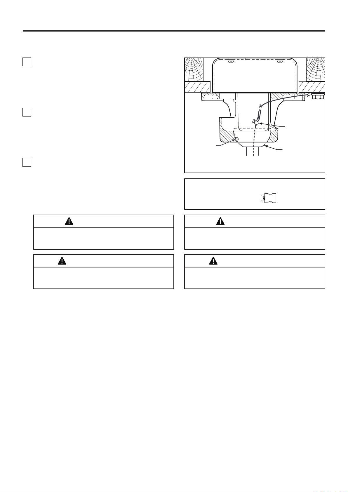
Cómo colgar el ventilador de techo (cont.)
3. Asegúrese de que los cables de suministro
eléctrico, incluido el cable de conexión a tierra del
soporte de suspensión y el cable de seguridad, hayan
atravesado el barral, entre el soporte de suspensión y
la caja de conexiones, de modo que más tarde se
pueda realizar la instalación eléctrica.
4. Levante cuidadosamente el ventilador y coloque el
ensamble de la bola para colgar/varilla en la
abrazadera para colgar que acaba de fijar a la caja de
salida. Asegúrese de que la ranura de la bola esté
alineada con la lengüeta de la abrazadera para
colgar. (Figura 4)
5. Fije el cable de seguridad al cable de soporte para
techo. Deslice la abrazadera de cables por el cable de
seguridad (del ventilador). Pase el extremo del cable a
través del aro que forma el cable de soporte para
techo. Tire lo más posible del cable a través del aro.
Inserte el extremo del cable en el orificio de la
abrazadera y ajuste firmemente el tornillo. (Figura 4)
NOTA: se omiten
los cables de
suministro y los
cables del
ventilador para
mayor claridad.
Pestaña
Abrazadera del
cable de soporte
Fije el cable de
seguridad al
cable de soporte
para techo
Unidad del barral/
de la semiesfera
Figura 4
Aditamentos utilizados:
x 1
ADVERTENCIA
Para evitar una posible descarga eléctrica, no apriete
los cables entre el ensamble de la bola para colgar y la
abrazadera para colgar.
AVERTISSEMENT
Ne pincez pas les fils entre la tige de suspension
descendante et le support de suspension éviter toute
électrocution.
ADVERTENCIA
Si no coloca la lengüeta en la ranura, podrían dañarse
los cables eléctricos y podrían ocurrir ncendios o
descargas eléctricas.
AVERTISSEMENT
Si vous n'installez pas la languette dans la rainure, vous
risquez d'endommager les fils électriques et de causer
éventuellement une décharge électrique ou un incendie.
34
Page 35
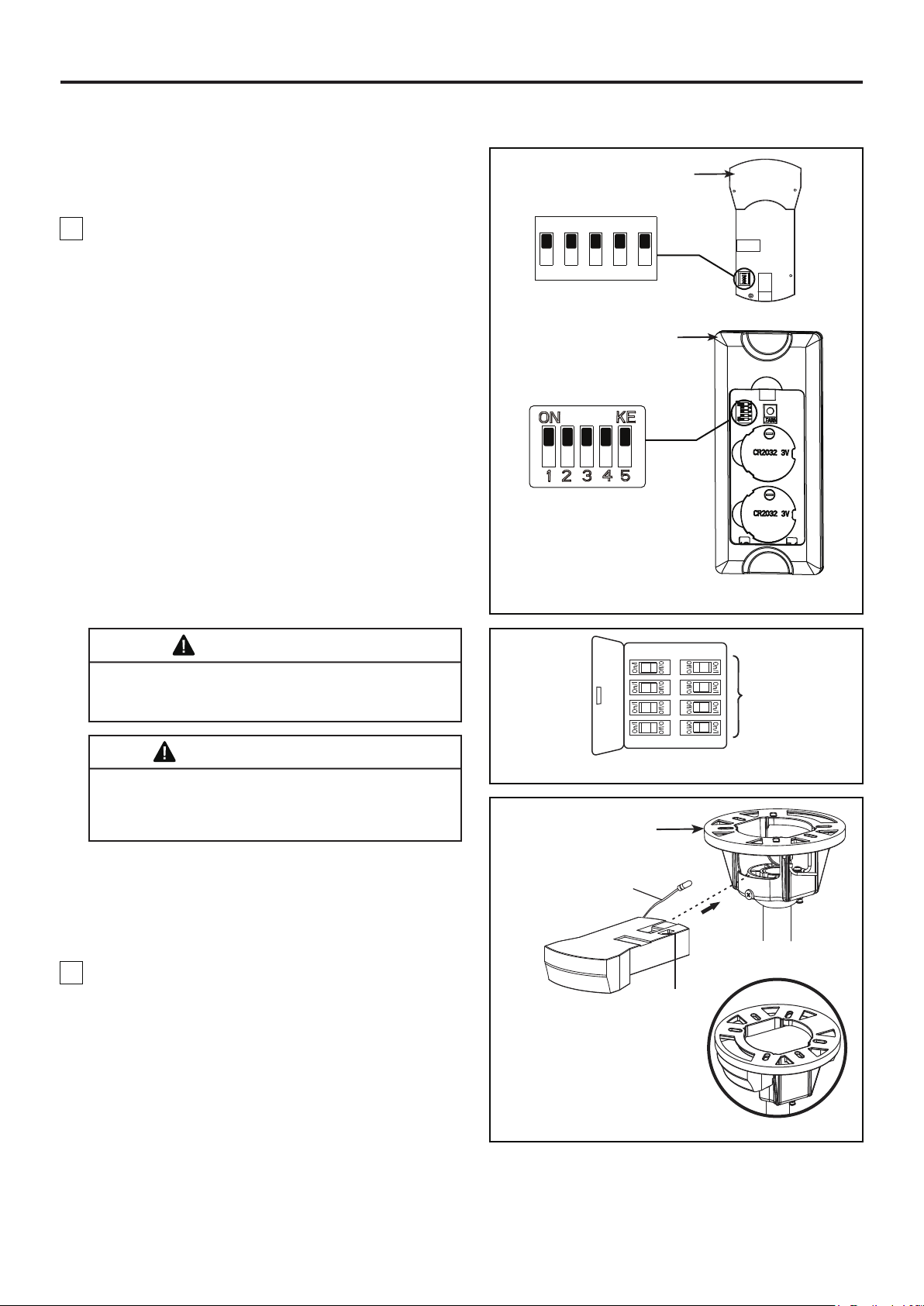
Cómo realizar la instalación eléctrica del ventilador de techo
NOTA: Si los cables de suministro o del ventilador son
de colores diferentes que los indicados, contrate a un
electricista calificado para que realice la instalación.
1. Para configurar el código de unidad del receptor.
Deslice los interruptores de código a las mismas
posiciones que en el transmisor. (Figura 1)
NOTA: El mando a distancia incluido en este
ventilador tiene 32 combinaciones diferentes de
códigos. Para evitar posibles interferencias desde o
hacia otros mandos a distancia, modifique el código
de combinación de su transmisor y receptor.
NOTA: Los ajustes de fábricas vienen con todos los
interruptores hacia arriba. No utilice esta posición.
Interruptores
ON
1 2 3 4 5
Mando a distancia
Interruptores
Receptor
ADVERTENCIA
Para evitar una posible descarga eléctrica, asegúrese
de cortar la alimentación eléctrica de la caja de fusibles
principal antes de alambrado el ventilador. (Figura 2)
AVERTISSEMENT
Pour éviter tout risque d'électrocution, assurez-vous
que l'alimentation électrique est coupée au niveau du
boîtier à fusibles principal avant d'effectuer le câblage.
(Figure 2)
NOTA: Si no está seguro de si la caja de salida tiene
conexión a tierra, pida consejo a un electricista
certificado, ya que debe tener conexión a tierra para
un funcionamiento seguro.
2. Deslice el receptor en el soporte de suspensión
antes de realizar el cableado como se muestra en la
figura 3.
Figura 1
Principal Caja
De Fusibles
Figura 2
Soporte de suspensión
Antena RF
(Dejar conectado
y no cortar)
Interruptores
35
NOTA: Se omiten los
cables de suministro
para mayor claridad.
Figura 3
Page 36
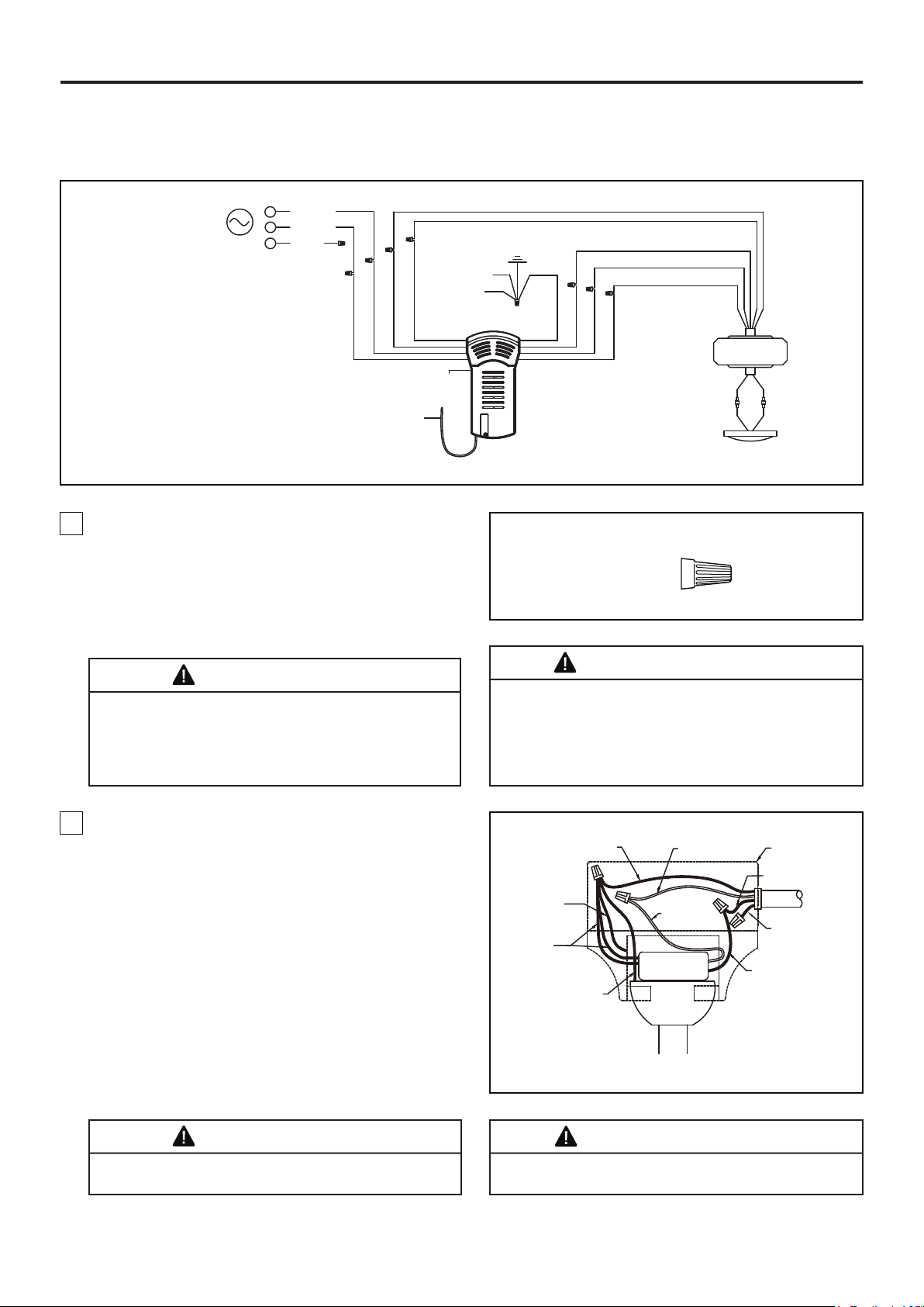
Cómo realizar la instalación eléctrica del ventilador de
techo (cont.)
Negro
ALIMENTACIÓN
DE CA
L
N
Blanco
L1
Rojo
Abrazadera
para colgar
Bola para
colgar
Azul
Negro
Blanco
Antena RF
Marrón
Receptor
Figura 4
3. Realice las conexiones de cables al bloque del
terminal como se muestra en la Figura 4.
PRECAUCIÓN: UNA CONEXIÓN INCORRECTA DEL
CABLE PODRÍA DAÑAR ESTE RECEPTOR.
ATTENTION: UNE CONNEXION DE FIL INCORRECTE
PEUT ENDOMMAGER CE RECEPTEUR.
Puesta a tierra
Amarillo /
Azul
Marrón
Verde (2)
Rojo
Conectores
de cable
Rojo
Gris
Amarillo
Gris
Amarillo
DC de MOTOR
Kit De Luz
Aditamentos utilizados:
AzulBlanco
X 9
ADVERTENCIA
Verifique que todas las conexiones estén ajustadas,
incluida la conexión a tierra, y que no haya conductores
desnudos visibles en los conectores. No opere el
ventilador hasta que las aspas estén instaladas. Podría
ocasionar ruidos y daños al motor.
4. Una vez haya hecho las conexiones, coloque los
cables hacia arriba y empújelos cuidadosamente
hacia dentro de la caja de la toma de corriente,
poniendo los cables blancos y verdes a un lado de la
caja y los negros hacia el otro lado. Los cables deben
ser colocados de forma extendida poniendo el
conductor de la toma de tierra y el conductor de toma
de tierra del equipo a un lado de la caja, colocando el
conductor sin toma de tierra en el otro lado de la caja.
(Figura 5)
AVERTISSEMENT
Vérifiez que tous les raccordements sont bien serrés, y
compris la mise à la terre, et qu’aucun fil dénudé n’est
visible au niveau des capuchons de connexion.Ne faites
pas fonctionner le ventilateur avant d'avoir installé les
pales. Du bruit et des dommages au moteur pourraient
en résulter.
Conductor verde
del suministro
(puesta a tierra)
Conductor verde
del soporte de
suspensión
(puesta a tierra)
Conductor
verde del
receptor (2)
(puesta a tierra)
Conductor verde
de la bola
para colgar
(puesta a tierra)
Conductor blanco
del suministro
Conductor
blanco
del receptor
Receptor
Caja de salida
homologada
Conductor negro
del suministro
Suministro
eléctrico
Conductor rojo
del suministro
Conductor negro
del receptor
Figura 5
ADVERTENCIA
Las aspas debe ser instalarse primero antes de
programación.
36
AVERTISSEMENT
Les lames doivent être installées avant la
programmation.
Page 37
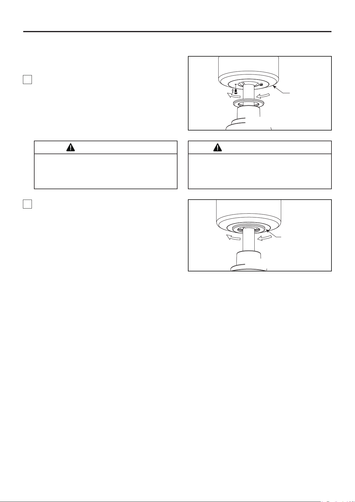
Cómo instalar la carcasa de la cubierta
NOTA: Este paso se debe realizar luego de completar
la instalación eléctrica necesaria.
1. Instale la cubierta rotando la ranura clave en la
cubierta sobre el tornillo de hombro del soporte del
gancho, teniendo cuidado de no pillar los cables. Fije
el tornillo de hombro. Instale adecuadamente y fije el
segundo tornillo de hombro que fue anteriormente
guardado. (Figura 1)
ADVERTENCIA
Para evitar posibles incendios o descargas eléctricas,
asegúrese de que los cables eléctricos se encuentren
completamente adentro de la cubierta del capuchón y
de que no estén aprisionados entre la cubierta y el
techo.
2. Coloque y ajuste firmemente la cubierta para el
tornillo de la base sobre los tornillos de reborde de la
abrazadera para colgar mediante el mecanismo de
seguro por giro del chavetero. (Figura 2)
Capuchón
de techo
Figura 1
AVERTISSEMENT
Pour éviter tout risque d'incendie ou de choc, assurezvous que les fils électriques sont complètement à
l'intérieur du boîtier de la monture et qu'ils ne sont pas
pincés entre le boîtier et le plafond.
Cubierta para el
tornillo del capuchón
Figura 2
37
Page 38
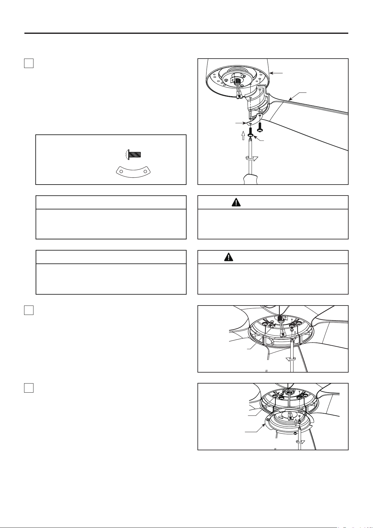
Cómo ensamblar las aspas del ventilador de techo y la tapa
1. Alinee los orificios del aspa con el poste el
ensamble del motor. Asegúrese de del aspa esté
completamente asentado sobre el volante del
ensamble del motor. Coloque la placa de la pala
sobre la pala con los orificios alineados e instale la
pala en la rueda giratoria usando los tornillos de
cabeza dentada, fije completamente los tornillos
para fijar las palas en la rueda giratoria del motor.
(Figura 1)
Placa de pala
Unidad del motor
Aspa
Aditamentos utilizados:
3/16”-24
Tornillos de cabeza dentada
Placa de pala
X 10
X 5
PRECAUCIÓN
No conecte las aspas hasta que el ventilador esté
totalmente instalado. Instalar el ventilador con las
aspas colocadas podría ocasionar daños en las
mismas.
ATTENTION
Ne raccordez pas les pales du ventilateur tant que le
ventilateur n'est pas complètement installé.
L'installation du ventilateur avec les pales assemblées
peut endommager les pales du ventilateur.
2. Extraiga uno de los tres tornillos del soporte
ubicado en la parte interior de la unidad del motor.
Guárdelo para después y afloje levemente los otros
dos tornillos. (Figura 2)
3/16˝-24
Tornillos de cabeza
dentada (2 por conjunto)
Figura 1
ADVERTENCIA
Para reducir el riesgo de lesiones personales, no doble
las aspas al instalar, balancear o limpiar el ventilador.
No coloque objetos extraños entre las aspas del
ventilador en funcionamiento.
AVERTISSEMENT
Afin de réduire le risque de blessure, ne pliez pas les
pales lors de l'installation, de l'équilibrage des pales,
ou du nettoyage du ventilateur. N'insérez pas de corps
étrangers entre les pales en rotation.
3. Instale la ensamble de la placa de iluminación en el
soporte utilizando las dos ranuras principales de
conexión. Vuelva a colocar el tornillo retirados
previamente y asegure los tres tornillos. (Figura 3)
38
Unidad del motor
Figura 2
Unidad del motor
Ensamble de la
placa de iluminación
Figura 3
Page 39
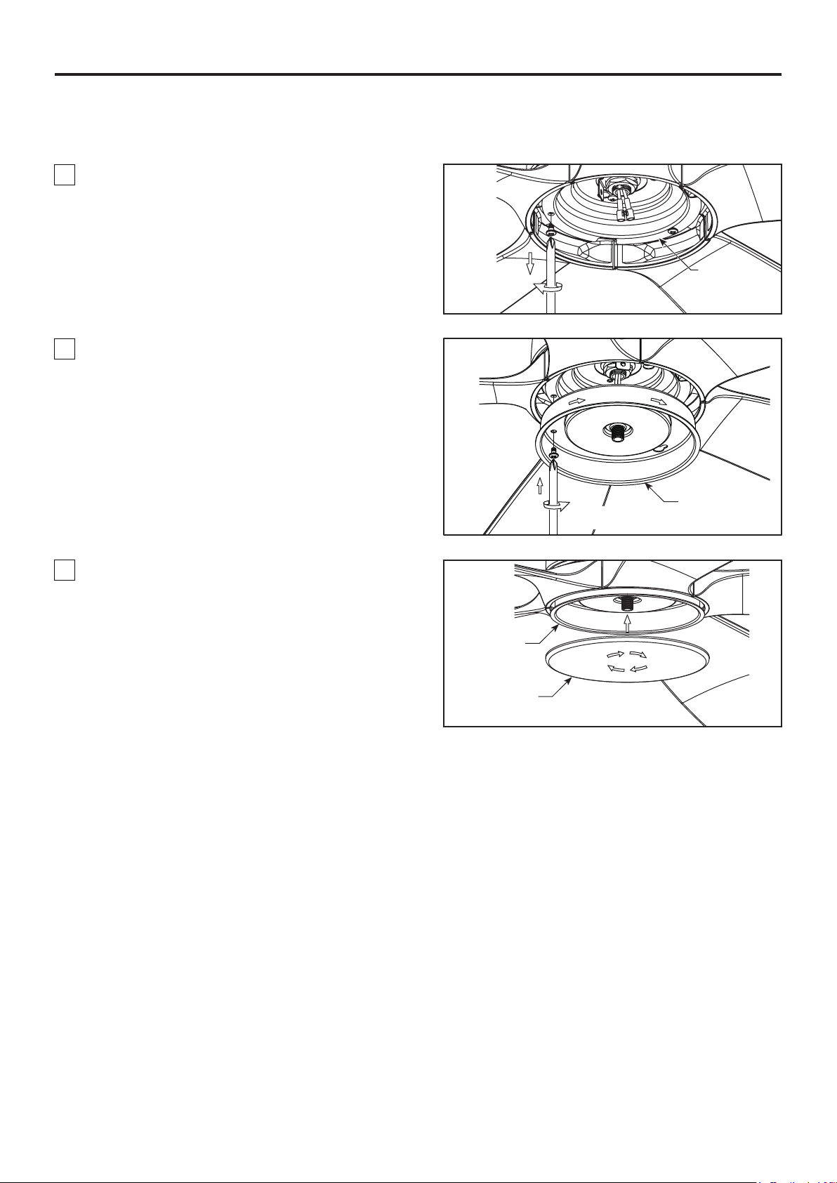
Cómo ensamblar las aspas del ventilador de techo y la
tapa (cont.)
4. Extraiga uno de los tres tornillos de ensamble de la
placa de iluminación. Guárdelo para después y afloje
levemente los otros dos tornillos. (Figura 4)
Ensamble
de la placa de
Figura 4
5. Instale la cubierta del cable del kit de iluminación
en la ensamble de la placa de iluminación usandos
las dos ranuras principales. Vuelva a colocar el tornillo
retirados previamente y asegure los tres tornillos.
(Figura 5)
Figura 5
iluminación
Cubierta del
cable del kit
de iluminación
6. Asegure el tapa de acero en la cubierta del cable
del kit de iluminación girándolo en el sentido de las
agujas del reloj y sin apretar demasiado. (Figura 6)
Cubierta del
cable del kit
de iluminación
Tapa de acero
Figura 6
39
Page 40
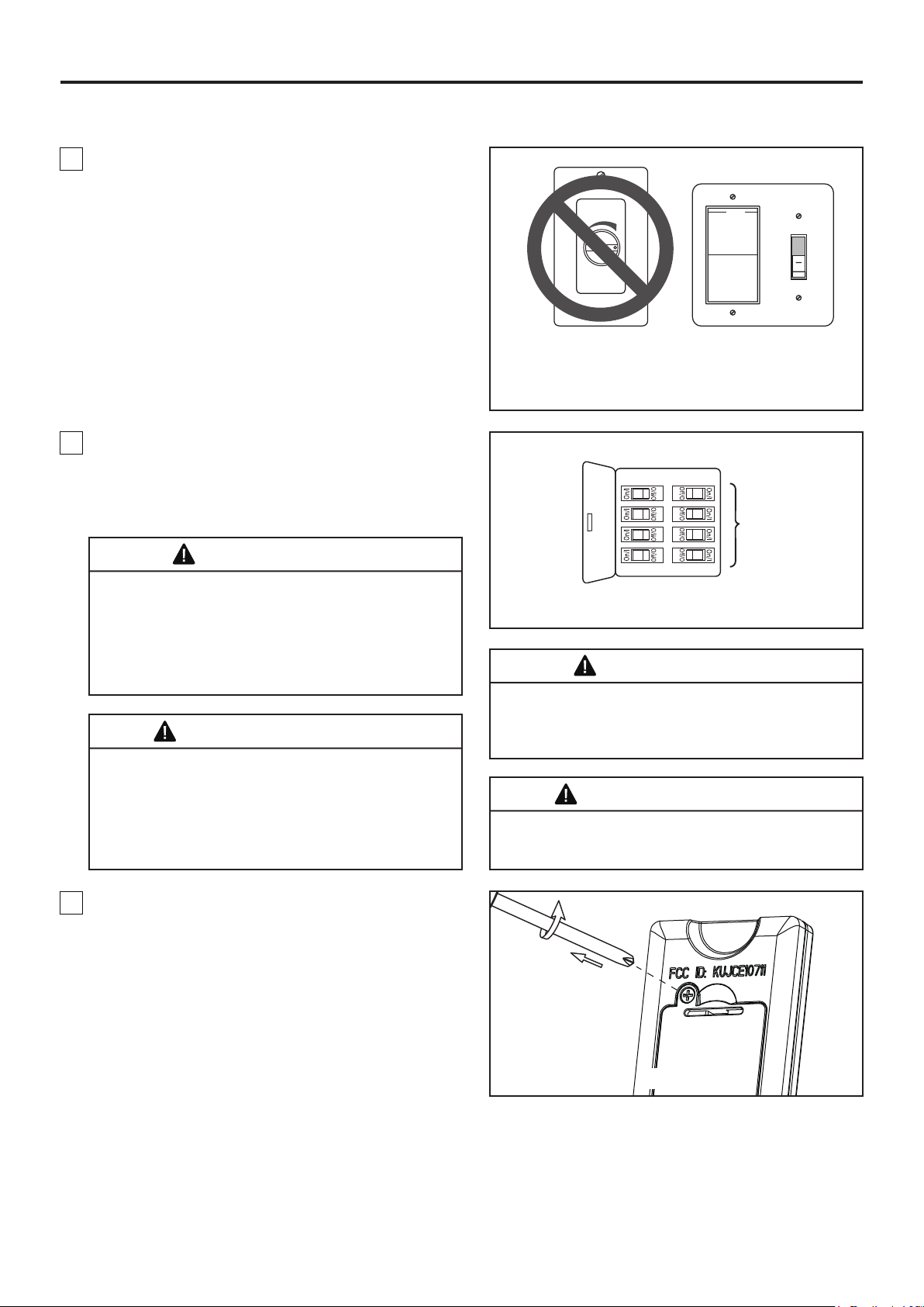
Cómo utilizar su ventilador de techo
1. IMPORTANTE: El uso de un regulador de la
intensidad completa (no incluido) para controlar la
velocidad del ventilador dañará el dispositivo. Para
reducir el riesgo de incendio o descarga eléctrica, no
utilice dicho regulador para controlar la velocidad del
ventilador. (Figura 1)
2. Restaure la fuente de alimentación de la toma de
corriente enciendo la electricidad del fusible principal.
(Figura 2)
ADVERTENCIA
Solo para referencia visual-no ha sido diseñado
para cubrir todos los tipos de controles
Figura 1
Principal Caja
De Fusibles
Compruebe que todas las conexiones realizadas
correctamente, incluyendo la toma de tierra, y que no se
visualizan ningún cable pelado en los conectores de
cables, con la excepción del cable de toma de tierra. No
utilice el ventilador hasta que las palas estén colocadas
en su lugar, ya que de lo contrario se podría causar
ruido y daños.
AVERTISSEMENT
Vérifiez que tous les raccordements sont bien serrés, y
compris la mise à la terre, et qu’aucun fil dénudé n’est
visible au niveau des capuchons de connexion, à
l’exception du fil de mise à la terre. Ne faites pas
fonctionner le ventilateur avant d'avoir installé les pales.
Du bruit et des dommages au ventilateur pourraient en
résulter.
3. Retire la cubierta de la batería del control remoto
con un destornillador y conserve el tornillo para luego.
(Figura 3)
Figura 2
ADVERTENCIA
No utilice este ventilador con un controlador variable de
pared (Rheostat) o un regulador de intensidad. Si lo
hiciera podría dañar la unidad del mando a distancia del
ventilador de techo.
AVERTISSEMENT
N'utilisez pas ce ventilateur avec un contrôleur mural
(rhéostat) variable ou un gradateur. Cela pourrait
endommager la télécommande du ventilateur de plafond.
40
Figura 3
Page 41
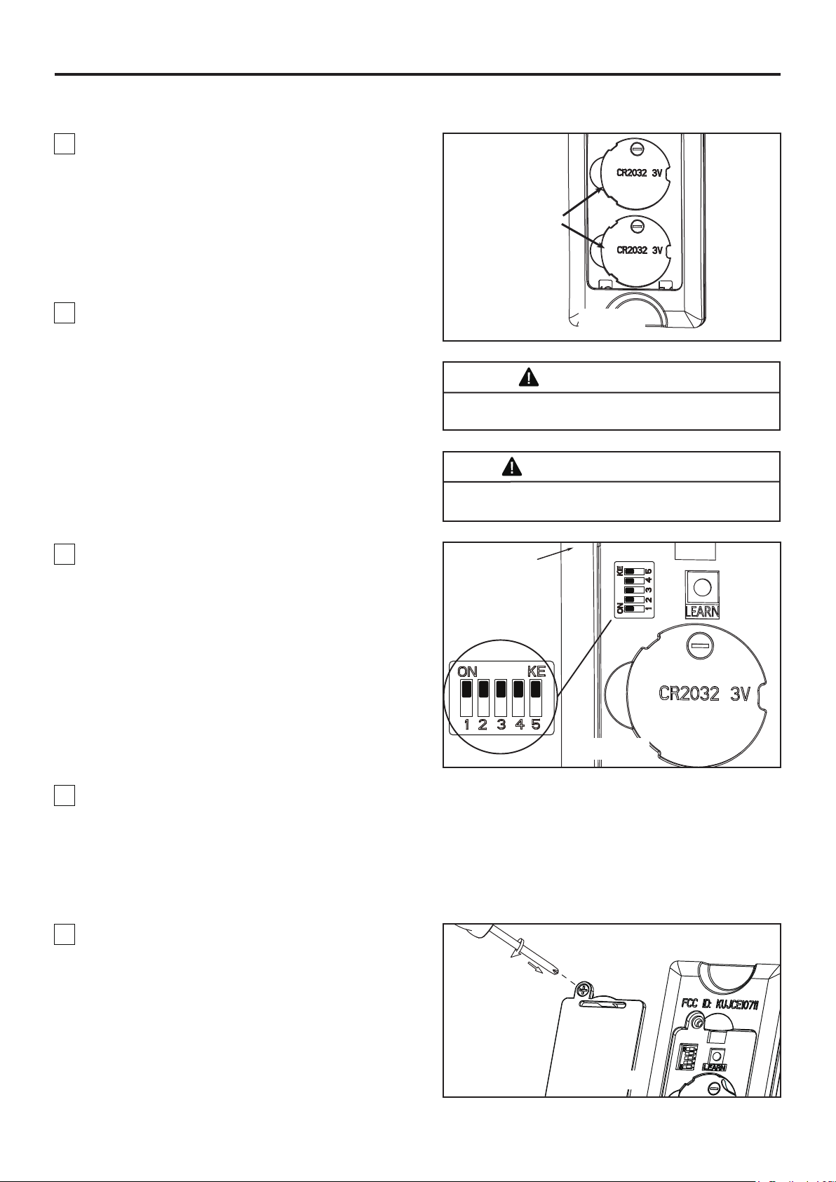
Cómo utilizar su ventilador de techo (cont.)
4. Para que el ventilador sea functional, instale las pila
(incluidas) de 3V en el transmisor del mando a
distancia. Mientras el ventilador esté apagado. A
continuación, siga el proceso de fijación remota de
código. Si no se utiliza el ventilador durante un largo
periodo de tiempo, extraiga la batería para evitar
cualquier daño al transmisor. Almacene el mando a
distancia en un lugar alejado del calor o la humedad
excesiva. (Figura 4)
Batería de
3V CR2032
(2 pc)
5. Si tiene varios ventiladores y desea programarlos
todos en un único mando a distancia, Deslice el
interruptor DIP a la misma posición en TODOS los
receptores a UN dispositivo móvil para configurar el
código de cada ventilador y siga el Paso 1 del
proceso de configuración de la velocidad del mando
a distancia. Cada ventilador necesita estar a menos
de 30 pies de distancia del mando al que desea
programarlo. Tenga en cuenta que el interruptor de
pared que controla la fuente de alimentación de su(s)
ventilador(es) debería estar en la posición apagado
hasta que esté listo para programar su(s) mando(s)
a distancia.
6. Si tiene múltiples ventiladores y desea programar
cada uno con mandos a distancia diferentes, Deslice
el interruptor DIP a la misma posición tanto en el
receptor como en el dispositivo móvil para configurar
el código de cada ventilador y siga el Paso 1 del
siguiente proceso de configuración de la velocidad del
mando a distancia. Repite estos pasos para cada uno
de los ventiladores que desea programar a un mandos
a distancia diferente. Tenga en cuenta que el
interruptor de pared que controla el encendido de
su(s) ventilador(es) debería estar en la posición
apagado hasta que esté preparado para programar
su(s) mando(s) a distancia.
Figura 4
ADVERTENCIA
Peligro de quemadura química. Mantenga las pilas
lejos del alcance de los niños.
AVERTISSEMENT
Risque de brûlure chimique. Gardez les piles hors
de portée des enfants.
Mando a
distancia
Interruptores
Figura 5
7. Para configurar el código del mando a distancia a
las mismas posiciones que en el receptor. Mueva los
interruptores de código hasta colocar el código de
selección en la posición arriba o abajo. Con un
destornillador pequeño o con una lapicera (no se
incluye) deslice firmemente hacia arriba o hacia
abajo. (Figura 5)
8. Vuelva a colocar la cubierta de la batería en el
mando a distancia con un tornillo retirados
previamente. (Figura 6)
NOTA: Los ajustes de fábricas vienen con todos los
interruptores hacia arriba. No utilice esta posición.
NOTA: El mando a distancia incluido en este
ventilador tiene 32 combinaciones diferentes de
códigos. Para evitar posibles interferencias desde o
hacia otros mandos a distancia, modifique el código
de combinación de su transmisor y receptor.
Figura 6
41
Page 42
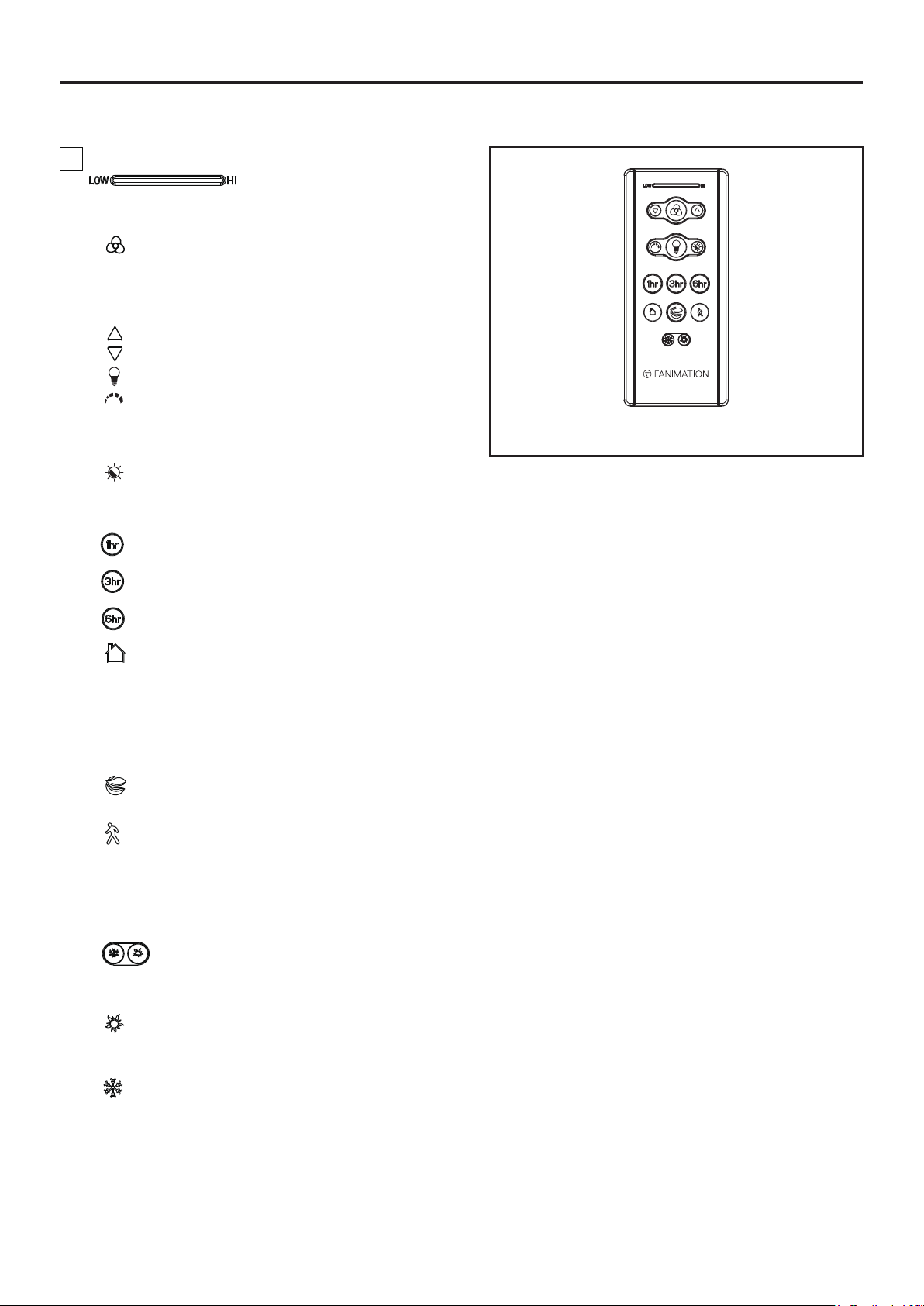
Cómo utilizar su ventilador de techo (cont.)
9. Funciones del control remoto: (Figura 7)
• Luz LED del indicador: Velocidad del ventilador e
indicador atenuante de la iluminación
• Botón: Toque este botón apaga el ventilador.
Mantenga pulsado el botón durante 5 segundos para
encender o apagalo el zumbador.
• Velocidad del ventilador:
Enciende el ventilador y aumenta la velocidad.
Enciende el ventilador y disminuye la velocidad.
• Botón de la lámpara: Enciende o apaga la luz.
Pulse el botón enciende la luz y mantenga el
regulador para aumentar o disminuir la
intensidad de la luz y suéltelo cuando haya
elegido el nivel deseado.
Cuando el luz estar en de encendido toque
este botón para cambiar temperatura de color.
• Temporizador de apagado automático:
El ventilador y la luz se apagará después de
1 horas.
El ventilador y la luz se apagará después de
3 horas.
El ventilador y la luz se apagará después de
6 horas.
Figura 7
• Lejos de casa: Toque este botón, la luz
parpadeará dos veces para indicarle que se habrá
completado el proceso de configuración, el ventilador
se apagará y la luz se encenderá y apagará
aleatoriamente mientras esté lejos, pulse ningún
botón(es) cancelar la función.
• Air Fresco: La velocidad del ventilador se
modulará para simular la brisa natural.
• Salida segura: Toque este botón, la luz
parpadeará dos veces para indicarle que se habrá
completado el proceso de configuración, la luz y el
ventilador se apagará después de 1 minuto, pulse
ningún botón(es) cancelar la función.
• Botón de reversa:
hacia delante o al revés. El ventilador debe estar
funcionando para podrá revertir la dirección.
Verano-El ventilador funciona en el sentido
contrario a las agujas del reloj. El flujo del aire
ofrece una brisa refrigerante hacia abajo.
Invierno-El ventilador funciona en el sentido
de las agujas del reloj. El flujo del aire fuerza el aire
caliente hacia abajo sin una brisa visible.
42
Page 43
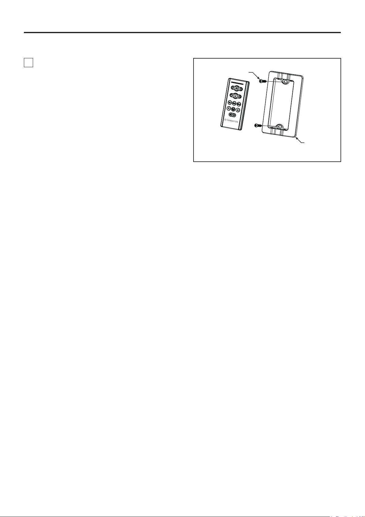
Cómo instalar su mando a distancia
1. Instalación de la placa de la pared: (Figura 1)
Fije la placa de la pared usando los dos tornillos
suministrados.
Tornillos (2)
Placa de
la pared
Figura 1
43
Page 44
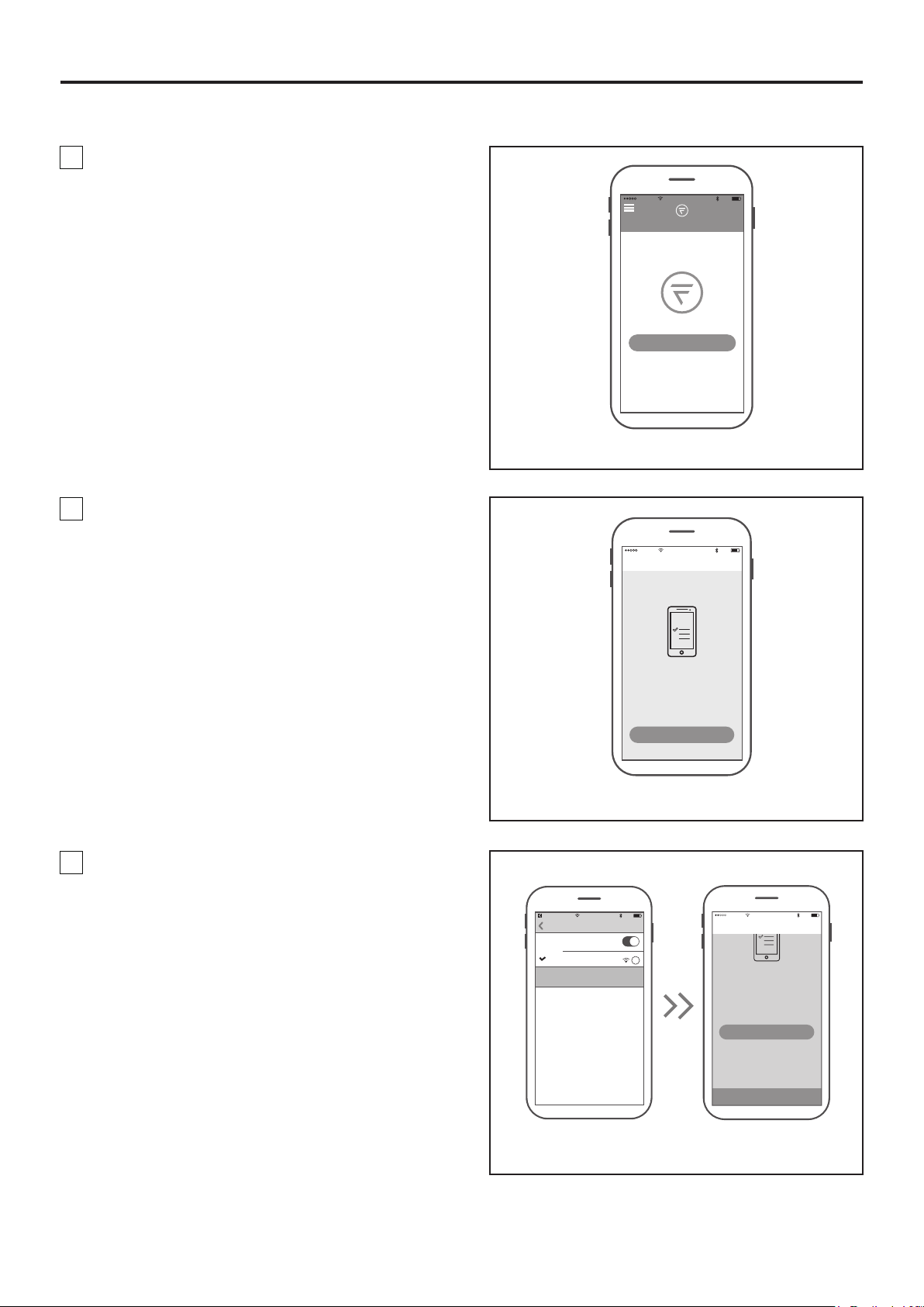
Configuración de la App fanSync WiFi
1. Visite el App Store de Apple o el Play Store de
Google para descargarse la App gratuita fanSync
WiFi. Cree su cuenta Fanimation fanSync. (Figura 1)
10:37 AM
80%
2. En este paso, el receptor WiFi de su ventilador de
techo debe estar instalado y dentro del rango de su
router WiFi. Con la App abierta, seleccione “añadir
dispositivo”. (Figura 2)
All
Your dashboard is empty
Add a Fanimation Ceiling Fans
Home
Figura 1
10:37 AM
Add Fainmation..
Connect To Your Dvice
WI-FI
80%
NOTA: El SSID WiFi predeterminada del dispositivo
es: Fanimation_XXXXXX (ej.: Fanimation_402AD4).
3. Seleccione el dispositivo Fanimation_XXXXXX y
vuelve a la App fanSync WiFi y pulse “CONTINUAR”.
(Figura 3)
10:38 AM
fanSync W...
Settings
Wi-Fi
Wi-FI
Fanimation_402AD4
Unsecured Network
CHOOSE A NETWORK
To begin you must first connect your phone
to the Fanimation Ceiling Fans you are
setting up. Your Fanimation Ceiling Fans will
broadcast a temporary Wi-Fi hotspot that
looks like
“Fanimation_xxxxxx”.
Go to Settings
Once you’ve completed this step come back
Figura 2
80%
i
To begin you must first connect your phone
setting up. Your Fanimation Ceiling Fans will
broadcast a temporary Wi-Fi hotspot that
Once you’ve completed this step, come back
10:39 AM
Add Fainmation..
to the Fanimation Ceiling Fans you are
looks like
“Fanimation_xxxxxx”.
Go to Settings
to the fanSync WiFi app to continue the
setup.
CONTINUE
80%
44
Figura 3
Page 45
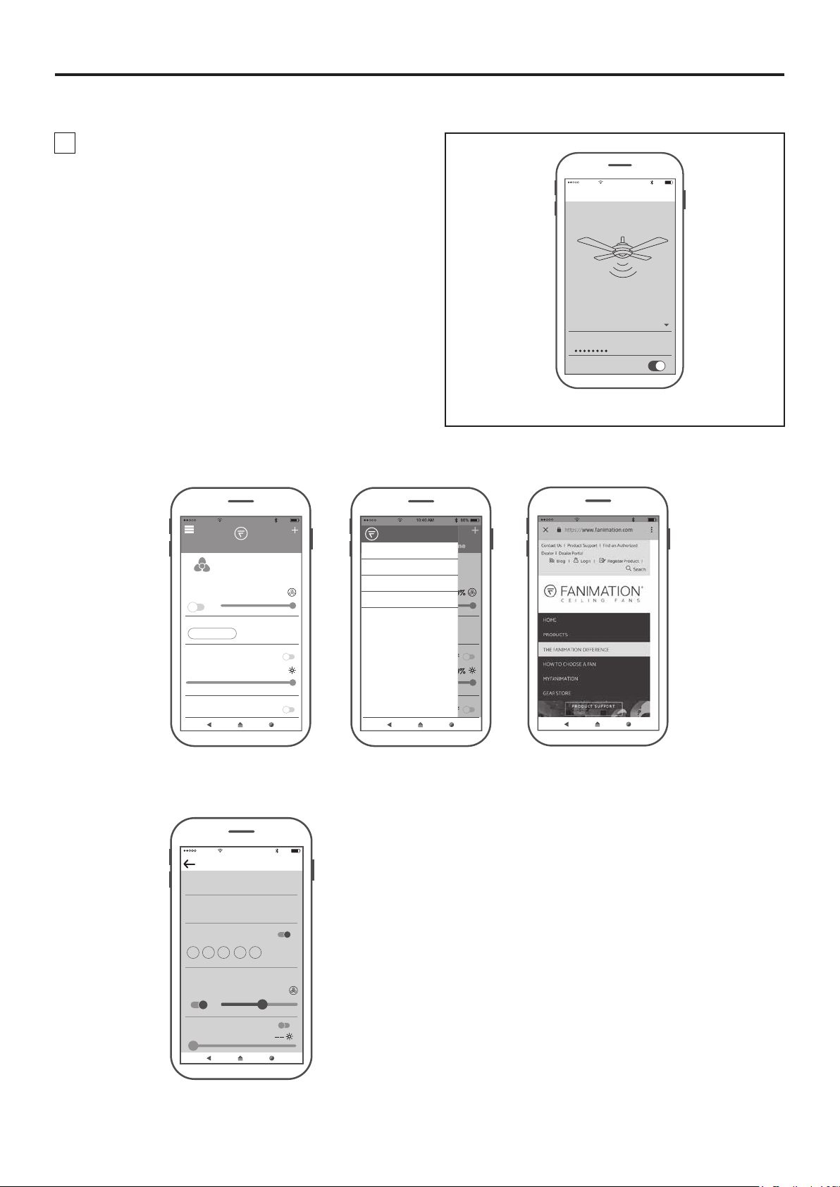
Configuración de la App fanSync WiFi (cont.)
4. Seleccione su router WiFi e introduzca la
contraseña WiFi para conectarse a su receptor WiFi
fanSync. Tardará 1 - 2 minutos en conectarse. Una
vez que su receptor WiFi se haya conectado, ahora
puede nombrar su ventilador de techo en la App y
personalizar sus ajustes. (Figura 4)
● Vista general de la App fanSync WiFi
10:40 AM
Add Fainmation..
Set Up Wi-Fi Network
Enter your network settings below to
connect your device online.
SSID
XXXXX
PASSWORD
Remember my SSID and pa...
Figura 4
80%
10:40 AM
All
Lounge
OFF 100%
BREEZE MODE
NORMAL
LIGHT
HOME AWAY
FRESH AIR
Home
OFF
100%
OFF
80%
HOME
MY GROUP
SETTINGS
SUPPORT
● Configuración de programación en tiempo real
10:43 AM
Edit Schedule
SCHEDULE NAME
Work Days
START TIME END TIME
8:00 PM 5:00 PM
REPEAT
M T W TH F SA SU
80%
ON
10:42 AM
80%
ON
Settings
51 %
OFFLIGHT
45
Page 46
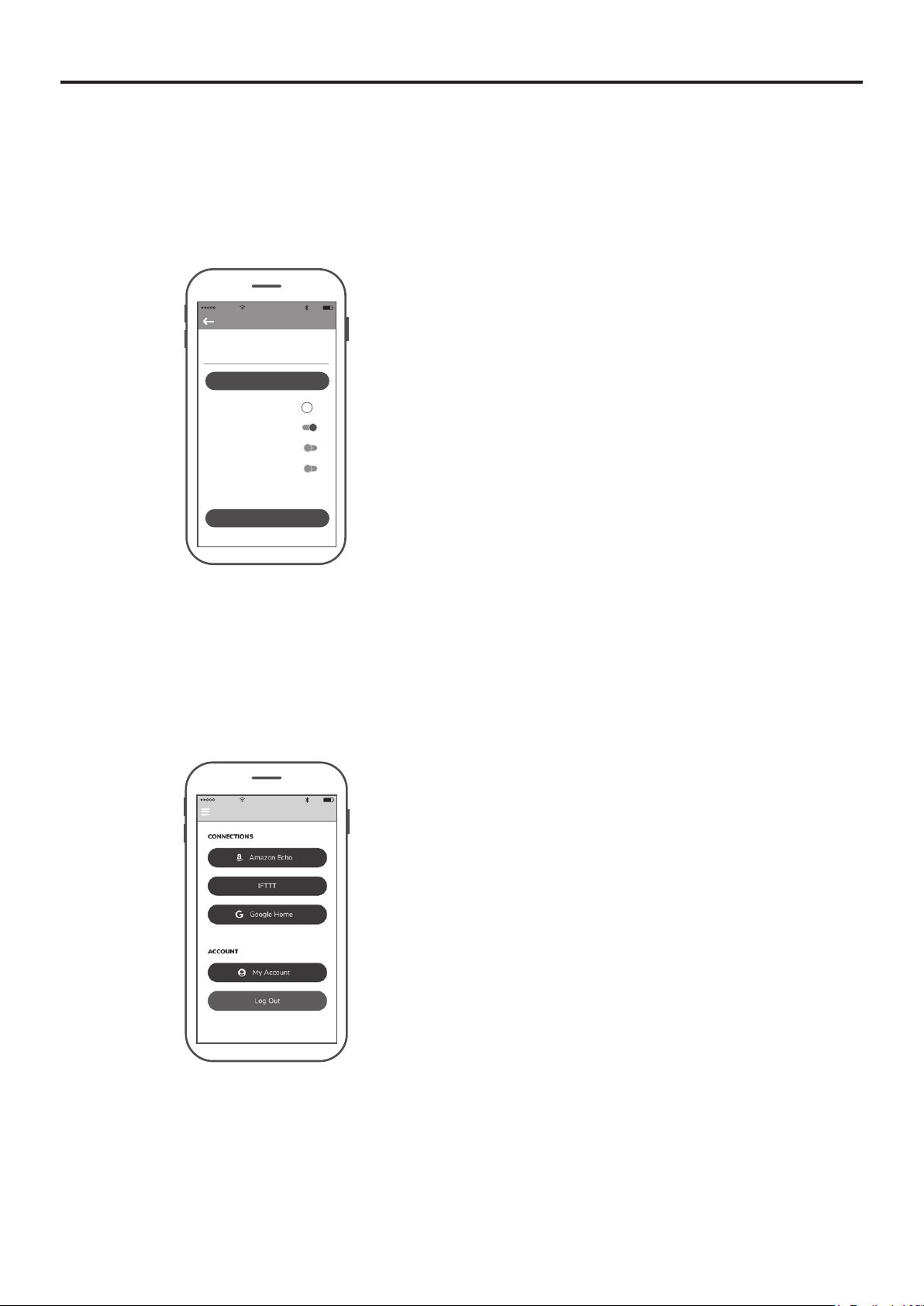
Configuración de la App fanSync WiFi (cont.)
● Compartir dispositivo
Una vez que un dispositivo inteligente es conectado
al ventilador, debe compartir el dispositivo con otros
usuarios para que otros usuarios de la App puedan
controlar el ventilador.
10:45 AM
Settings
DEVICE NAME
Lounge
Save
EXTRA DEVICE CONTROLS !
HIDE FAN DIRECTION
HIDE LIGHT POWER
HIDE LIGHT DIMMER
FAMILY SHARING
SHARE DEVICE
80%
● Enlace con Amazon Echo, Google Home y IFTTT
Seleccione el dispositivo que desee conectar y siga las instrucciones en el procedimiento de configuración.
Ayuda para Amazon Alexa: https://www.amazon.com/gp/help/customer/display.html?nodeId=201749240
Para conectarse a NEST, ECOBEE, Samsung Smart things, wink, etc. debe conectarse a través de IFTTT.
Ayuda para IFTTT: https://help.ifttt.com/hc/en-us/articles/115010325748-What-is-IFTTTAyuda de Google: https://support.google.com/googlehome/answer/7073578?hl=en
10:46 AM
Settings
80%
46
Page 47
Mantenimiento
El único mantenimiento necesario para el ventilador de
techo es una limpieza periódica.
Al llevar a cabo la limpieza, use sólo un cepillo suave o un
paño sin pelusas, para evitar rayar el acabado.
No se requieren agentes abrasivos de limpieza; los
mismos deben evitarse para prevenir daños en el acabado.
Limpieza de las aspas
Se recomienda limpiar el polvo de las aspas
periódicamente. Lo mejor es utilizar un plumero.
PRECAUCIÓN
No utilice solventes para limpiar el ventilador de
techo. Podrían dañar el motor o las aspas y ocasionar
posibles descargas eléctricas.
ATTENTION
N'utilisez pas d'eau pour nettoyer votre ventilateur de
plafond. Cela pourrait endommager le moteur ou la
finition, et créer une possibilité d'électrocution.
Evite usar agua, productos de limpieza o trapos
ásperos, que pueden combar o dañar las aspas.
47
Page 48
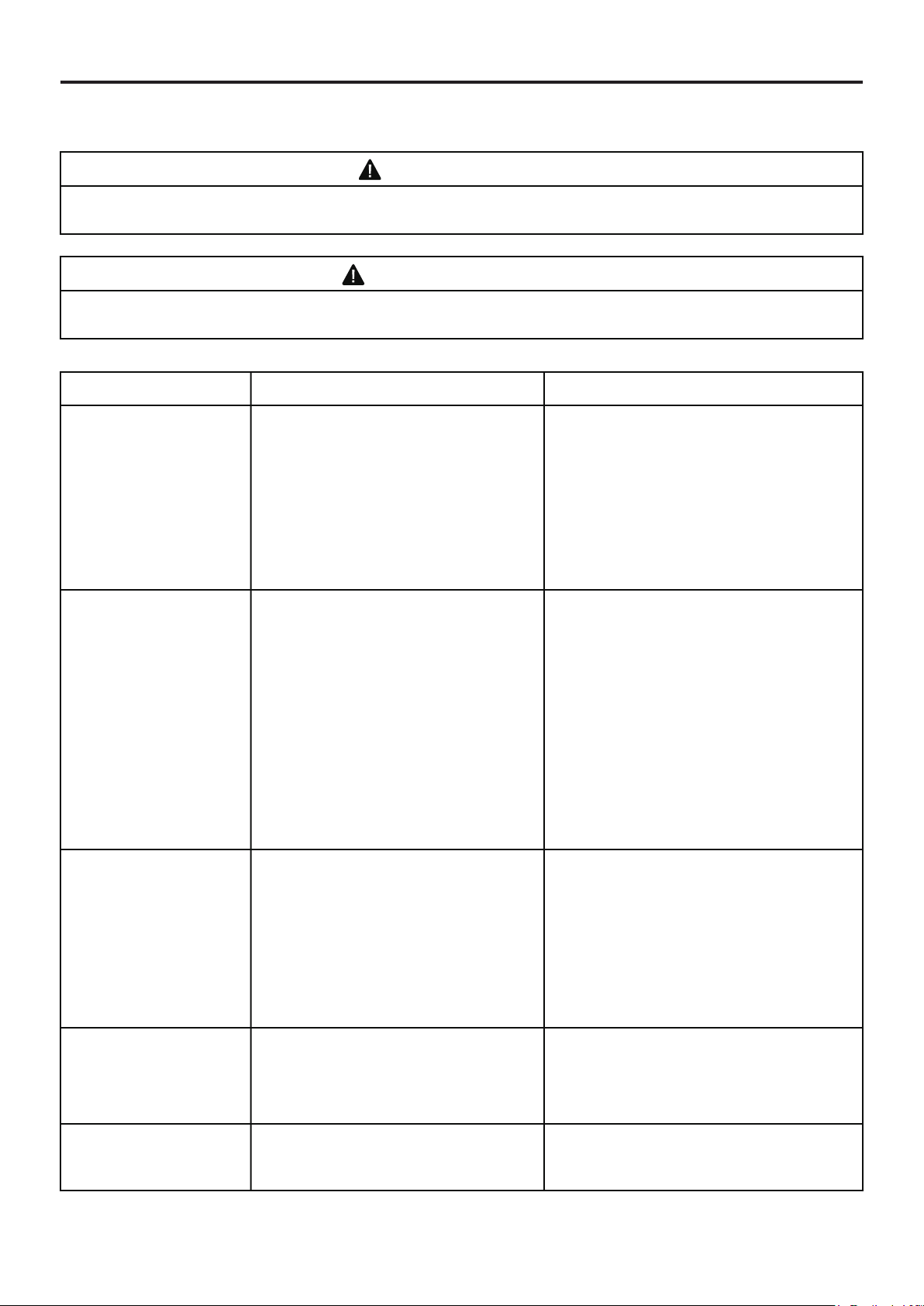
Solución de problemas
ADVERTENCIA
Para su propia seguridad, desconecte la electricidad de la caja de fusibles o disyuntor antes de
solucionar problemas en su ventilador.
AVERTISSEMENT
Pour votre sécurité, placez le coffret à fusibles ou le disjoncteur hors tension avant de tenter
d’identifier tout problème pouvant affecter votre ventilateur.
Problema Causa posible Solución sugerida
1. EL VENTILADOR NO
ARRANCA.
2. EL VENTILADOR HACE
RUIDO.
1. El fusible o el disyuntor están fundidos.
2. Las conexiones eléctricas del ventilador o del
interruptor en la caja del interruptor están flojas.
3. Pila agotada del mando a distancia.
1. Las aspas no están sujetas al ventilador.
2. Hay tornillos flojos en la caja del motor.
3. Los tornillos que aseguran las aspas al buje del
motor están flojos.
4. El tornillo del soporte de la cubierta inferior está
flojo.
1. El tornillo de fijación y la tuerca del soporte de
barral están flojos.
1. Controle los fusibles del circuito principal y derivado
o los disyuntores.
2. Controle las conexiones eléctricas del ventilador y
del interruptor en las cajas de los interruptores.
PRECAUCIÓN: ¡Asegúrese de que el suministro
principal de electricidad esté desconectado!
ATTENTION: Assurez-vous que l'alimentation
électrique principale est coupée !
3. Sustituir con una pila nueva.
1. Ajuste las aspas al ventilador antes de ponerlo en
funcionamiento.
2. Asegúrese de que todos los tornillos de la caja del
motor estén bien ajustados (pero no en exceso).
3. Asegúrese de que los tornillos que fijan las aspas al
buje del motor del ventilador estén bien ajustados.
PRECAUCIÓN: ¡Asegúrese de que el suministro
principal de electricidad esté desconectado!
ATTENTION: Assurez-vous que l'alimentation
électrique principale est coupée !
4. Asegure bien los tornillos de fijación.
1. Ajuste bien los dos tornillos de fijación y las tuercas
en el soporte de barral.
3. EL VENTILADOR
OSCILA EN EXCESO.
4. EL MANDO A DISTANCIA
SIN FUNCIONAR. EL LED
INDICADOR DE CONTROL
PARPADEA
CONSTANTEMENTE.
5. NO HAY SUFICIENTE
MOVIMIENTO DE AIRE.
2. El tornillo de fijación en la unidad del barral/de la
semiesfera está flojo.
3. Los tornillos que aseguran las aspas al buje del
motor están flojos.
4. El soporte de suspensión o la caja de distribución
eléctrica del techo no están bien asegurados.
48
2. Ajuste el tornillo de fijación en la unidad del barral/de
la semiesfera.
3. Asegúrese de que los tornillos que fijan las aspas al
buje del motor del ventilador estén bien ajustados.
4. Ajuste los tornillos del soporte de suspensión de la
caja de distribución eléctrica y asegúrela.
1. Sustituir con la batería/baterías (pila/pilas) nueva.1. La batería/baterías (pila/pilas) se van a agotar.
1. Si es posible, considere el uso de un barral más largo.
Por ejemplo (no incluido, usted puede comprar el
tiempo de la vara hacia abajo fanimation.com).
Page 49
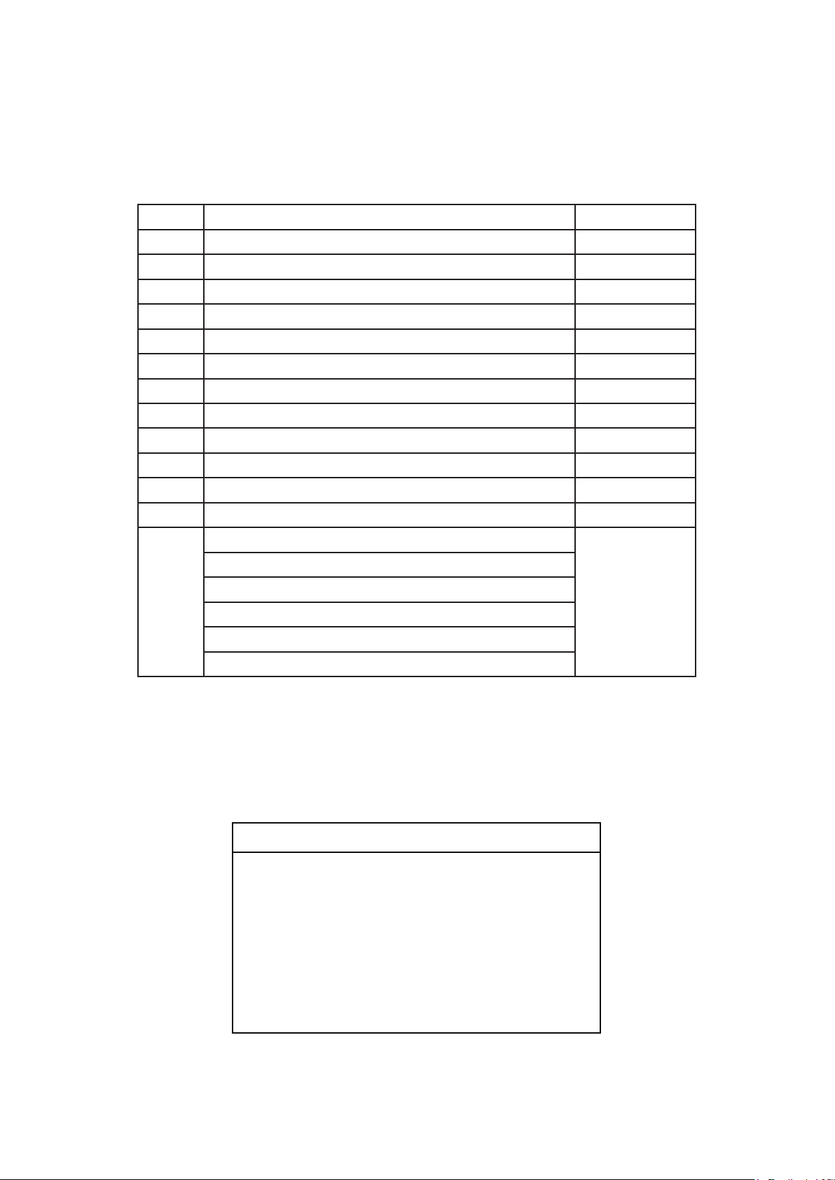
Lista de piezas
Modelo N.° FPD5534**
N.° de Ref.
1
2
3
4
5
6
7
8
9
10
11
12
13
Descripción Pieza # N.°
Unidad del soporte de suspensión
Unidad del barral / de la semiesfera
Capuchón de techo
Cubierta para el tornillo del capuchón
Cubierta de unión del motor
Unidad del motor
Juego de aspas AP553405**
Ensamble de la placa de iluminación AP853407BL
Cubierta del cable del kit de iluminación AP853413BL
Tapa de acero P853414**
Receptor
Mano a distancia
Bolsa de accesorios:
Kit de cable de seguridad
Conectores de cables (4)
Bolsa de accesorios para el montaje de aspas que contiene:
3/16˝-24 tornillos de cabeza dentada (11)
AP255BL
ADR1-45**
P853401**
AP260**
AP853404**
AMA5534**
WFRCCD553400
TR305
HDWFPD5534**
Placa de pala (5)
**Inserte los CÓDIGOS DE ACABADO (consulte el número de modelo del ventilador que se
encuentra en el soporte de barral)
Antes de desechar los materiales de embalaje, asegúrese de haber extraído todas las piezas
Cómo hacer un pedido de piezas
Al hacer un pedido de piezas de repuesto,
proporcione siempre la siguiente información:
• Número de modelo del ventilador
• Número de pieza
• Descripción de la pieza
• Código de fecha
Póngase en [email protected] o
al 1-888-567-2055 para obtener las piezas de
repuesto.
49
Page 50
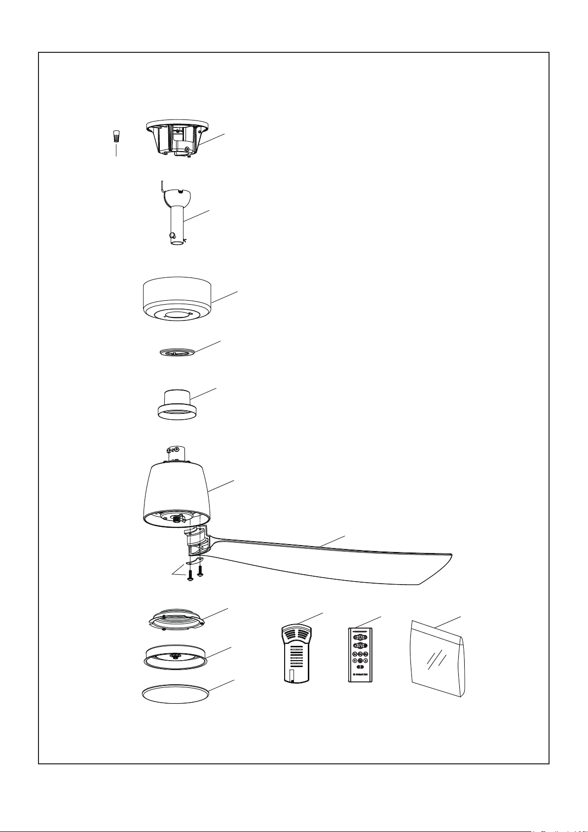
KUTE5
™
52
Modelo FPD5534**
Ilustración del despiece
13
1
2
3
4
13
5
6
7
8
9
11
12
13
10
NOTA: La ilustración que se muestra no está hecha a escala y su configuración real y/o terminación puede variar.
50
Page 51
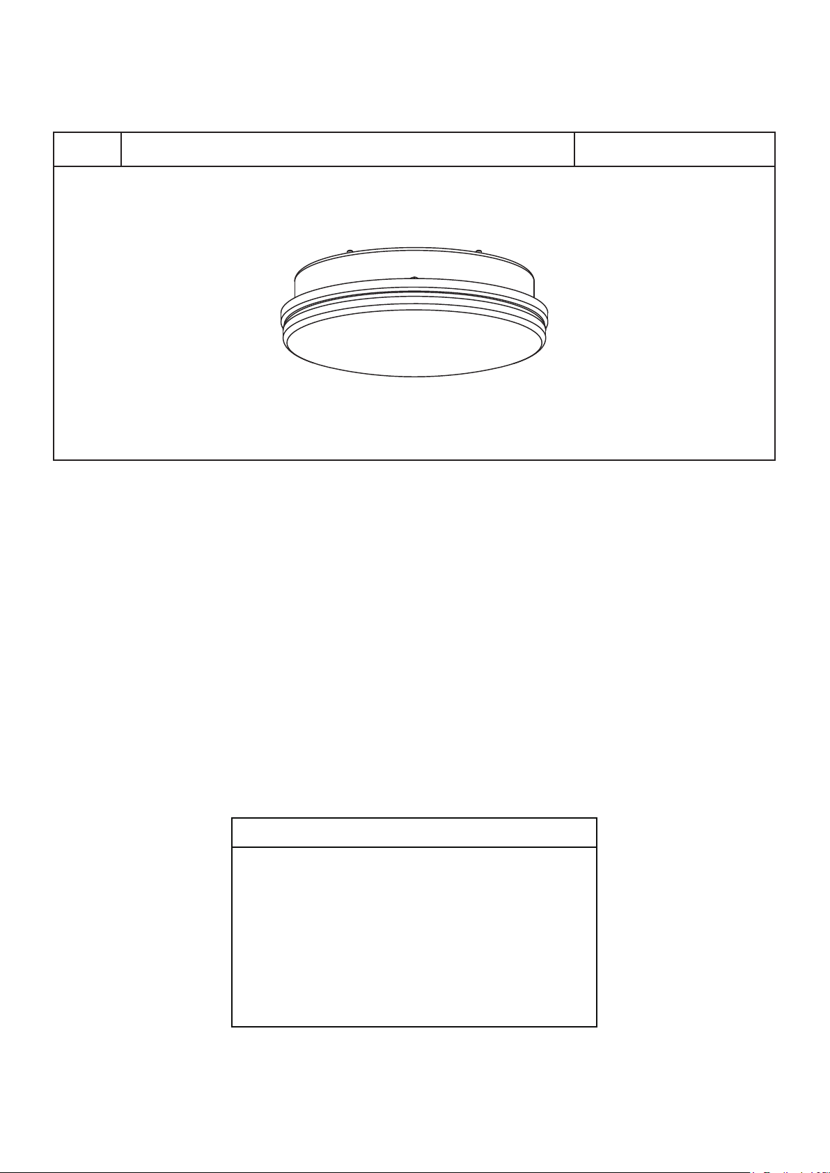
Kit de iluminación opcional
Ensamble de kit de iluminación1 LK8534**
NOTA: La ilustración que se muestra no está hecha a escala y su configuración real y/o terminación puede variar.
Antes de desechar los materiales de embalaje, asegúrese de haber extraído todas las piezas
Cómo hacer un pedido de piezas
Al hacer un pedido de piezas de repuesto,
proporcione siempre la siguiente información:
• Número de modelo del ventilador
• Número de pieza
• Descripción de la pieza
• Código de fecha
Póngase en [email protected] o
al 1-888-567-2055 para obtener las piezas de
repuesto.
51
Page 52

10983 Bennett Parkway
Zionsville, IN 46077
Llame sin cargo al (888) 567-2055
FAX (866) 482-5215
Desde fuera de los EE.UU., llame al (317) 733-4113
Visite nuestro sitio Web en www.fanimation.com
2022/03 V.01
Copyright 2022 Fanimation
 Loading...