

Page 1
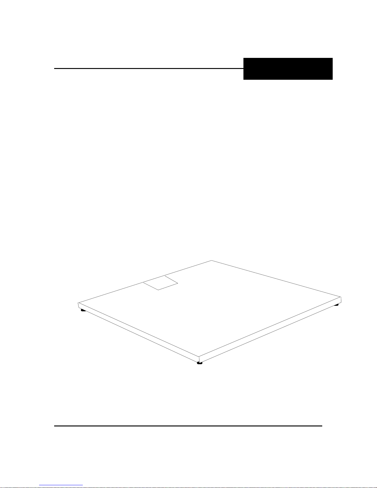
Service Manual
Floor Scale
© 1997, 2002, 2008 by Fancor, Inc. Revision 9 03/08
All rights reserved
50612
Page 2

Page 3

Amendment Record
FLOOR SCALE
Document #50612
Manufactured by Fancor, Inc.
821 Locust
Kansas City, Missouri 64106
Issue 1
Issue 2 11/97
Issue 3 08/01 Update the procedures.
Issue 4 10/01 Update the Electrical Schematic on page 6.
Issue 5 11/01 Removed brand name references.
Issue 6 01/02 Updated manual.
Issue 7 05/02 Added note on page 16.
Issue 8 12/02 Corrected part number on analog series parts list.
Updated note callouts.
Revision 9 03/08 Revised date of load cell(s).
Removed references to stainless steel model.
Altered image: 21896 MS.
03/08 3 50612 Rev. 9
Page 4

Disclaimer
Every effort has been made to provide complete and accurate information in this manual. However,
although this manual may include a specifically identified warranty notice for the product, Fancor, Inc.
makes no representations or warranties with respect to the contents of this manual, and reserves the
right to make changes to this manual without notice when and as improvements are made.
It is the responsibility of the requesting party to develop, maintain, install, and connect networking
devices and general network connectivity as it applies to the originating party’s network. No warranty
or guarantee, expressed or implied, concerning the network, its design, its installation, or operational
characteristics has been offered by Fancor, Inc. Fancor, Inc. shall not be liable for any loss, damage,
cost of repairs, incidental or consequential damages of any kind, whether or not based on express or
implied warranty, contract, negligence, or strict liability arising in connection with the design,
development, installation, or use of an intended network.
© Copyright 1997, 2002, 2008 by Fancor, Inc.
This document contains proprietary information protected by copyright. All rights are reserved; no part
of this manual may be reproduced, copied, translated or transmitted in any form or by any means
without prior written permission of the manufacturer.
03/08 4 50612 Rev. 9
Page 5

Table of Contents
SECTION 1: GENERAL INFORMATION ..................................................................7
Introduction.......................................................................................................................... 7
Description........................................................................................................................... 7
SECTION 2: COMPANY SERVICE INFORMATION..................................................8
General Service Policy ........................................................................................................ 8
Overview.............................................................................................................................. 9
Physical Installation Notes.............................................................................................................. 9
Conferring with Our Client .............................................................................................................. 9
Pre-Installation Checklist ..............................................................................................................10
Unpacking.....................................................................................................................................10
Equipment Checkout .................................................................................................................... 11
Users’ Responsibility.....................................................................................................................11
SECTION 3: SCALE INSTALLATION......................................................................12
Load Cell Wiring............................................................................................................................13
Calibration Steps...........................................................................................................................14
SECTION 4: INSTALLING ACCESSORIES ............................................................16
Installing Bolt-Down Plates...........................................................................................................16
Installing Ramps ...........................................................................................................................17
Installing Bumper Guards............................................................................................................. 17
Installing Pit Frames .....................................................................................................................18
SECTION 5: PARTS REPLACEMENT.....................................................................20
Load Cell Replacement ................................................................................................................ 20
Load Cell Specifications ............................................................................................................... 21
Junction Box Replacement...........................................................................................................21
Foot Assembly Replacement........................................................................................................ 22
SECTION 6: PARTS.................................................................................................23
Parts List.......................................................................................................................................23
Parts Diagram...............................................................................................................................24
APPENDIX I: LOAD CELLS INSTALLED BEFORE 01/08......................................25
APPENDIX II: MODEL MATRIX...............................................................................26
APPENDIX III: ACCESSORIES................................................................................27
Ramps, Bumper Guards and Pit Frames ..................................................................................... 27
Bolt-down Plates, Eyebolts and Hole Plugs ................................................................................. 27
APPENDIX IV: PIT FRAME INSTALLATION...........................................................28
03/08 5 50612 Rev. 9
Page 6

Page 7

Section 1: General Information
INTRODUCTION
The Floor Scale is available in two series.
• The Analog Series using a standard junction box for interfacing to most analog
indicators
• The Intalogix™ series using a Quad Multiplexer Box (QMB) for interfacing to an
Intalogix™ Technology indicator.
NOTE: It is the owner's responsibility to document, notify, and follow-up regarding
shipping damage with the carrier.
DESCRIPTION
• The scale platform is shipped in a crate, fully assembled and wired.
• The floor scale sizes range from 30” x 30” to 6' x 8'.
• The floor scale capacities range from 1K to 10K (lbs).
• Both scale types are equipped with a twenty-five (25) foot interface cable.
• The junction box is constructed of stainless steel and all models have threaded
holes in the decks for attaching eyebolts to facilitate installation and cleaning.
NOTE: Specifications and sizes are shown in Appendix II.
03/08 7 50612 Rev. 9
Page 8

W
Section 2: Company Service Information
GENERAL SERVICE POLICY
Prior to installation, always verify that the
equipment satisfies the customer's
requirements as supplied, and as described
in this manual.
If the equipment cannot satisfy the application and the application cannot be
modified to meet the design parameters of the equipment, the installation
should NOT be attempted.
It is the customer/operator's responsibility to ensure the
equipment is operated within the parameters of the equipment's
specifications and protected from accidental or malicious damage.
Absolutely NO physical, electrical or program modifications other
than selection of standard options and accessories can be made
by customers to this equipment
Repairs are performed by Service Technicians and Authorized
Distributor Personnel ONLY!
ARNING!
Failure to comply with this policy voids all implied and/or written
warranties
03/08 8 50612 Rev. 9
Page 9

Section 2: Company Service Information
OVERVIEW
Physical Installation Notes
• Check all devices for proper operation. If any error messages occur, refer to
Troubleshooting or the proper manual of that device.
• Only those charges which are incurred as a result of the equipment's
inability to be adjusted to performance specifications may be charged to
warranty.
• No physical alterations (mounting holes, etc.) are allowed during installation.
The installing technician is responsible that all personnel are fully
trained and familiar with the equipment's capabilities and
limitations before the installation is considered complete.
• All electrical assemblies must be replaced as assemblies or units.
─ Replacement of individual components is not allowed.
─ These components must be returned intact for replacement credit per normal
procedures.
• All electronic and mechanical adjustments are considered to be part of the
installation, and are included in the installation charge(s).
─ Included is any required computer programming or upgrades.
─ Included are any accuracy and/or operational specification changes.
• The AC receptacle / outlet shall be located near the Indicator and easily
accessible.
• Electrical connections other than those specified may not be performed.
Conferring with Our Client
• The technician must be prepared to recommend the arrangement of components
which provide the most efficient layout, utilizing the equipment to the best possible
advantage.
• The warranty policy must be explained and reviewed with the customer.
03/08 9 50612 Rev. 9
Page 10

Section 2: Company Service Information
Pre-Installation Checklist
The following points should be checked and discussed with the Area Sales Manager
and/or customer, if necessary, before the technician goes to the site and installs the
equipment.
9 Check the customer's application to make certain it is within the capabilities and
design parameters of the equipment.
9 If the installation process might disrupt normal business operations, tell the
customer and ask that they make ample arrangements.
9 Be sure that the equipment operator(s) are available for
training.
9 The service technician reviews the recommended setup with
the Area Sales Manager or Area Service Manager, and
together they identify all necessary variations to satisfy the
customer's particular application.
Unpacking
Follow these guidelines when unpacking all equipment:
9 Check in all components and accessories according to the customer's order.
9 Remove all components from their packing material, checking against the invoice
that they are accounted for and not damaged.
Advise the shipper immediately, if damage has occurred.
Order any parts necessary to replace those which have been damaged.
Keep the shipping container and packing material for future use.
Check the packing list.
9
Collect all necessary installation manuals for the equipment
and accessories.
9 Open the equipment and perform an inspection, making
certain that all hardware, electrical connections and printed
circuit assemblies are secure.
9 Do not reinstall the cover if the final installation is to be
performed after the pre-installation checkout.
03/08 10 50612 Rev. 9
Page 11

Section 2: Company Service Information
Equipment Checkout
Position the equipment with these points in mind:
9 Intense direct sunlight can harm the display.
9 Do not locate near magnetic material or equipment/Indicators which use magnets
in their design.
9 Avoid areas which have extreme variations in room temperatures. Temperatures
outside the Indicator’s specifications will affect the weighing accuracy of this
product.
9 Do not load the platform if there is any evidence of damage to the platform or
supporting structure.
Users’ Responsibility
9 All electronic and mechanical calibrations and/or adjustments required for making
this equipment perform to accuracy and operational specifications are considered
to be part of the installation.
─ They are included in the installation charge.
─ Only those charges which are incurred as a result of the equipment's inability to
be adjusted or calibrated to performance specifications may be charged to
warranty.
9 Absolutely no physical, electrical or program modifications other than selection of
standard options and accessories are to be made to this equipment.
9 The equipment consists of printed
circuit assemblies which must be
handled using ESD handling
procedures, and must be replaced as
units.
─ Replacement of individual
components is not allowed.
─ The assemblies must be properly
packaged in ESD protective material
and returned intact for replacement
credit per normal procedures.
03/08 11 50612 Rev. 9
Page 12
Section 3: Scale Installation
1. Select a location that is flat, solid, level, and one that fully supports the weight of
the platform plus a full capacity load.
2. Remove the top of the crate and all packing material.
3. Screw the two (2) eyebolts into the threaded adapters in the platform top.
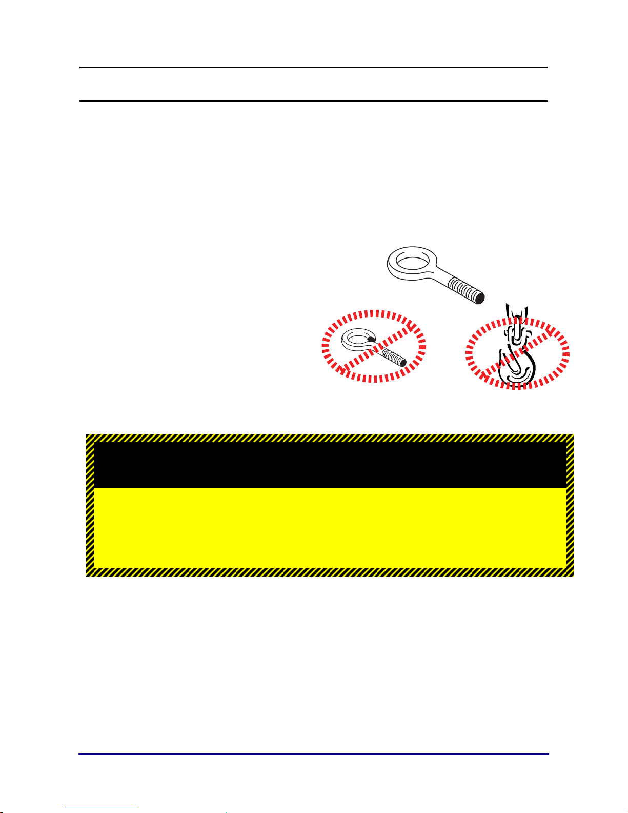
4. Use a forklift or other lifting means, along with chains, cables, or nylon straps to
remove the scale from the crate bottom.
TWO TYPES of EYE BOLTS
9 Closed Gap Eyebolts
• Open Gap Eyebolts (NOT USED)
• Lifting Hooks (NOT USED)
CAUTION
DO NOT use hooks or unclosed eyebolts.
Failure to use proper lifting tools may result
in personal injury.
5. Set the scale so that the interface cable exits in a direction where it can be
protected.
─ If possible, use a cable protector to reduce 'trip' hazards and to protect the
interface cable from being damaged.
6. Level the scale by removing the hole plugs in the corners, then use a screwdriver
to turn the threaded 'leg' of the foot assembly.
03/08 12 50612 Rev. 9
Page 13
Section 3: Scale Installation
INSTALLATION, CONTINUED
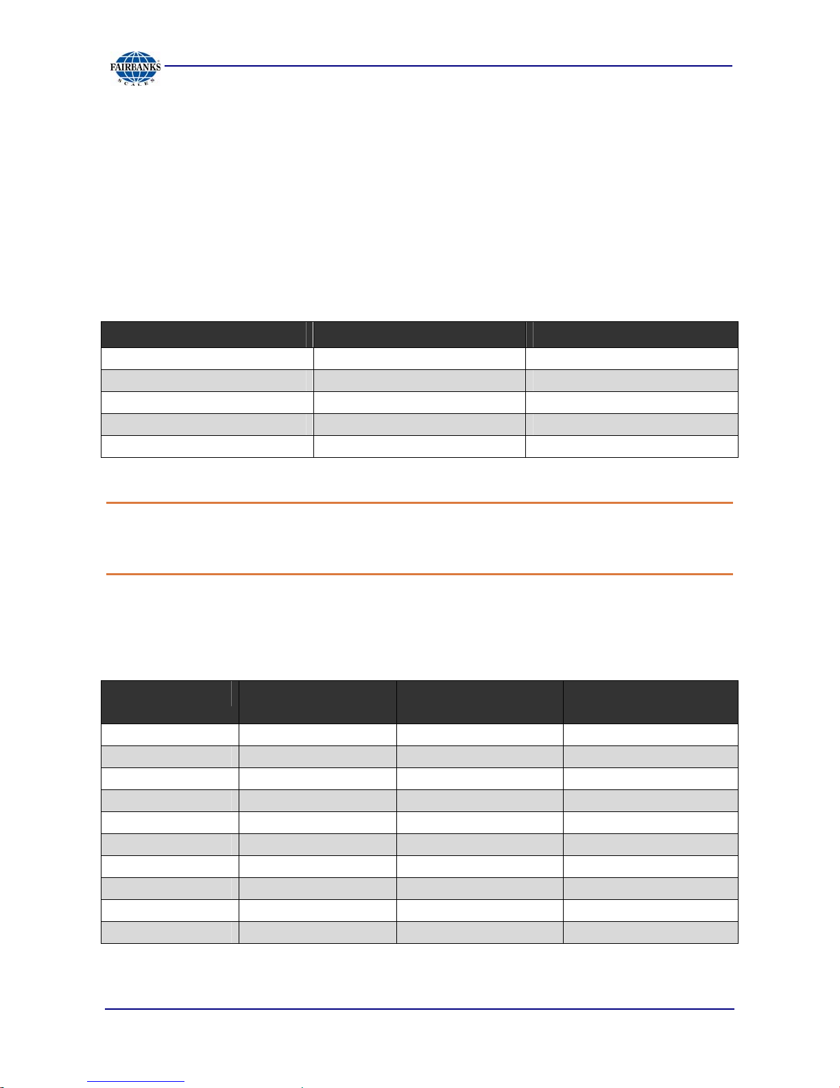
7. Wire the scale cable to the proper type indicator, as shown in the chart below.
8. Once the scale platform is completely wired to the indicator, calibrate the unit.
─ Follow the appropriate indicator service manual to ensure a good calibration.
─ Typically, the Load Cells are pre-wired and connected.
Analog Interface (Junction Box 67171)
WIRE COLOR FUNCTION ANALOG INSTRUMENT
Black (─) Excitation (─) Excitation
Green (+) Excitation (+) Excitation
Yellow Shield Shield
White (+) Signal (+) Signal
Red (─)Signal (─)Signal
Note: Models manufactured before March 2008 may contain the following load
cell parts, and use the West Coast wiring style:
y 58902 – 1K, 2.5K y 12896 – 5K y 63593 – 10K
Wiring Connections for an Intalogix™ Technology
Interface (QMB 15291)
QMB Terminal WIRE COLOR FUNCTION ANALOG
INSTRUMENT
1 Green (─) Excitation 1
2 Red (+) Excitation 2
3 Black Ground 3
4 White D Out 4
5 Brown D In 5
6 Blue EOC 6
7 Orange SCLK 7
8 Yellow CS 8
9 Violet Temperature 9
10 Gray/Shield Chassis 10
03/08 13 50612 Rev. 9
Page 14
Section 3: Scale Installation
Calibration Steps
Adjust the analog interface indicator to the platform.
• Install all the corners to within one (1) division of each other at 25% of
rated capacity.
• Follow the appropriate indicator service manual to ensure a proper calibration.
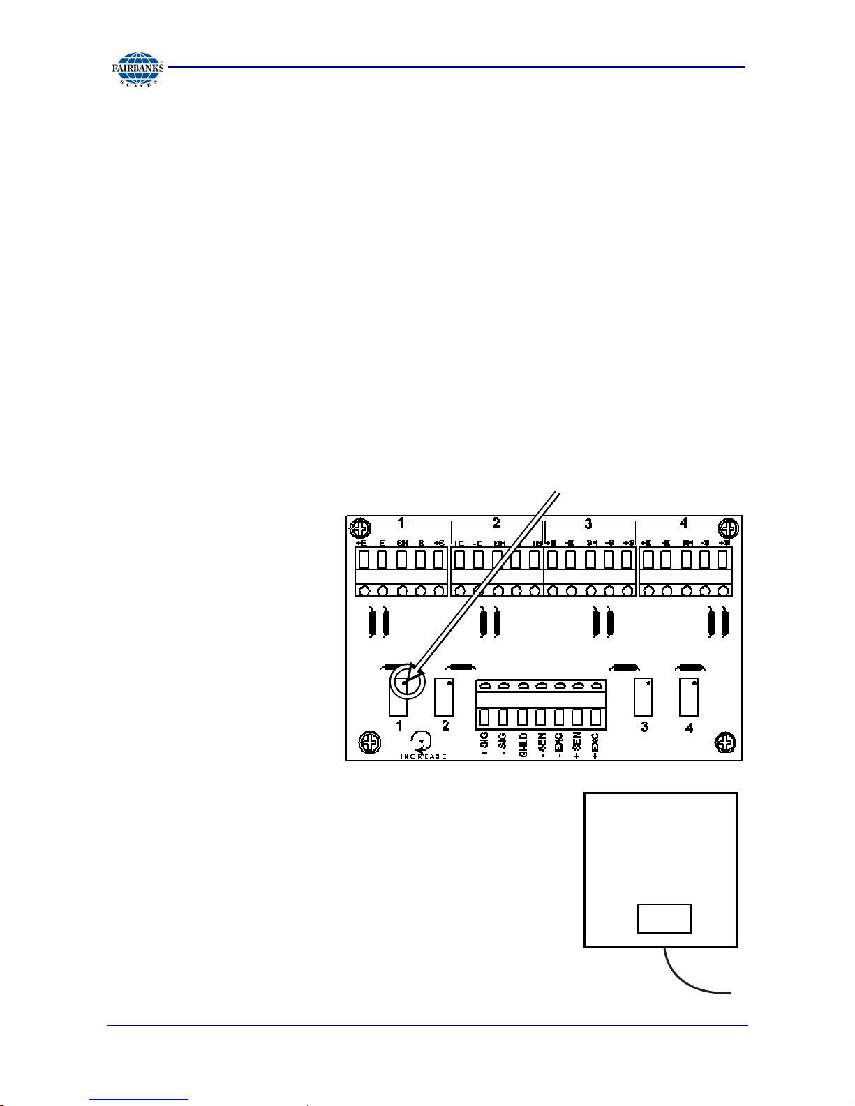
The Junction Box Assembly (P/N 67171) has four (4) extended range, multi-
turn potentiometers, one for each load cell.
STEPS
1. Center the four Junction Box Potentiometers by turning the adjustment screw
counter-clock-wise position until a clicking sound is heard, then turning each of
them back clock-wise ten (10) turns.
─ Total number of turns is twenty.
2. Identify the platform corner numbers.
3. Place a concentrated weight (
25% of platform capacity)
on corner #1, then move it to #2, #3 and #4, noting the
displayed reading on each corner.
2
3
4. Identify the lowest reading, and then place the
concentrated weight on this corner.
03/08 14 50612 Rev. 9
1
4
50612-1
Page 15

Section 3: Scale Installation
If corners do require adjustment, complete the following steps:
1. Place the concentrated weight on the corner displaying the lowest weight.
2. Turn the adjustment on the potentiometer clockwise (
CW) to the displayed weight
so it reads the same as the highest reading.
3. Repeat this procedure while rechecking all corners until they are equal.
Important Note: When moving the weight(s) from corner to corner, DO NOT
zero the scale. The purpose is to adjust the corners to be the same, and not to
perform a correct calibration.
4. Perform a zero reference check with an unloaded platform,
5. Repeat the corner test to ensure all readings are the same before proceeding.
If ‘cornering' the platform is difficult, follow these steps.
1. Note which corner has the highest reading.
2. Turn all potentiometers to the full counter-clock-wise position until a
clicking sound is heard.
3. Place the weight on the lowest reading corner.
4. Turn the corresponding potentiometer clock-wise to read the same as the
corner with the highest reading.
5. Repeat each corner to match the one with the highest reading.
If corners do not require adjustment, complete the following steps:
1. Remove all weights.
2. Zero the indicator.
3. Perform a final calibration with test weights.
4. Follow the appropriate indicator service manual to ensure a proper calibration.
03/08 15 50612 Rev. 9
Page 16

Section 4: Installing Accessories
Installing Bolt-Down Plates
Bolt down plates are used to keep the scale from sliding or moving when loads are
applied. The plates are bolted using anchors at each of the scales feet.
STEPS
1. Place the platform into the correct position.
2. Place the bolt-down plate under the foot. The plate edge extends out from under
the scale.
3. Drill two (2) 7/16” attachment holes using a hammer drill.
4. Insert anchors with the nut and washer already on them.
5. Tap the anchor into the hole, then tighten the nuts securely.
6. Repeat this process for each plate.
Note: If ramps are not installed and bolt-down plates are needed, then a full set of
four bolt-down plates are required.
03/08 16 50612 Rev. 9
Page 17

Section 4: Installing Accessories
Installing Ramps
Each mild steel ramp accessory comes with two integral bolt-down plates and four
anchors.
STEPS
1. Place the ramp in position, then lift and set the platform feet into the bolt-down
plate holes.
2. Drill the
nut and washer already on.
3. Tap the anchor into the hole, then tighten the nuts securely.
two (2) 7/16” holes using a hammer drill. Insert the anchors with the
IMPORTANT TIPS
• If two ramps are installed, then no other bolt-down plates are needed.
• If only one ramp is installed, then a set of two bolt-down plates are necessary.
• Only two ramps (total) may be installed on opposite sides of a scale platform.
Installing Bumper Guards
Bumper Guards help protect the platform from direct hits from forklift traffic. The
guards are slightly higher than the scale and help deflect the forks.
STEPS
1. Place the bumper guard into a position so it protects the platform from non-scale
traffic.
─ Place the bumper guard so it does not touch or interfere with the platform’s
movement.
2. Drill the 7/16” fastening holes using a hammer drill.
3. Insert the anchors with the nut and washer already on it.
4. Tap the anchor into the hole.
5. Tighten the nuts securely.
03/08 17 50612 Rev. 9
Page 18

Section 4: Installing Accessories
Installing Pit Frames
The pit frame accessory is a one-piece welded unit.
─ There are three (3) different type frames with six (6) sizes for each type.
─ Two (2) are for the standard duty scale and one (1) is for the heavy capacity.
─ The Pit Frame is designed for in-floor, or 'flush', applications.
─ Standard duty frames are available in mild steel for all six floor scale sizes
For normal installations, a hole is cut in the concrete, the pit-frame accessory is
installed in the hole, then concrete is poured around and under the frame.
─ The concrete work and frame setting is usually done by a contractor, with a
scale technician completing the project by setting and installing the scale.
─ Once cured, the scale platform is set into the frame and installation can be
completed. No additional welding required.
STEPS
1. Place the pit frame in the approximate position it will occupy on
the floor.
2. Mark out the position of the hole to be made.
─ The hole MUST be a
sides than the pit frame.
─ The hole will have to be deep enough to accommodate the pit coping, plus the
thickness of the pit floor.
─ Use the drawing in Appendix IV for measurements.
─ Should pit drainage be required, slope the pit floor to an installed drain while
maintaining a level area at each corner.
3. Cut the hole in the concrete floor.
4. Clean up any debris in the way of further installation steps.
minimum of twelve inches (12") wider on all
5. Set the frame in the hole supported at about the correct height.
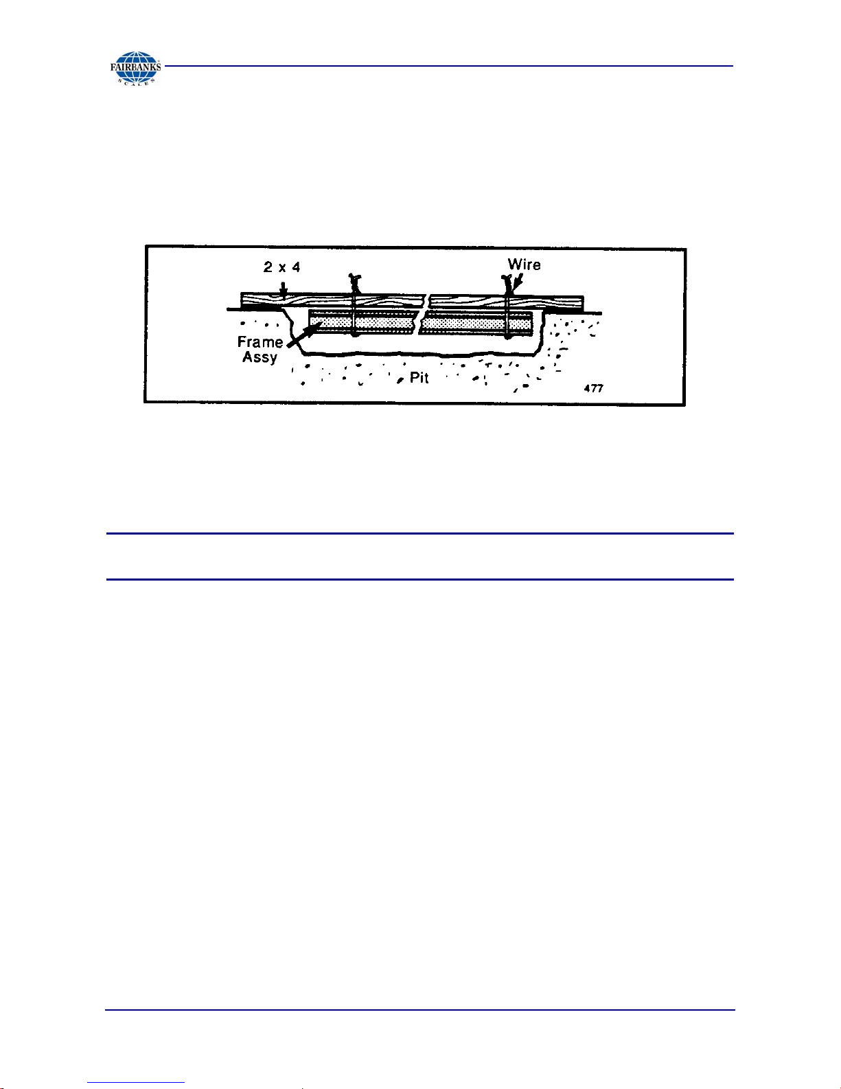
6. Set two 2x4 's on edge (longer than the width of the hole) across the opening.
03/08 18 50612 Rev. 9
Page 19
Section 4: Installing Accessories
Installing Pit Frames, Continued
7. Use soft wire and make two (2) loops by twisting wire around each 2x4 and
the frame.
8. With the frame supported by the wire and 2x4's, use a level to set the frame flush
with the surrounding floor, level, and at the correct height by twisting or untwisting
the wire.
NOTE: Use the drawing in Appendix IV for measurements, concrete
specifications and amounts.
9. Set into place and secure the conduit for the scale cable into the frame opening.
10. Pour the concrete around and under the frame.
11. Level and smooth it with a hand trowel, as needed.
12. If a drain is required, form the pit to place a slope in the pit floor to the drain.
─ See
─ Allow cement to cure to a
13. Pull the cable through the conduit before placing the scale platform in the frame.
14. Level the platform before installing the instrumentation.
Appendix IV.
minimum of 2000 psi before cutting the wire.
03/08 19 50612 Rev. 9
Page 20

Section 5: Parts Replacement
Load Cell Replacement Steps
1. Cycle-down the power to the indicator, then unplug the unit.
2. Remove the platform and junction box access covers.
3. Disconnect the failed load cell cable(s) at the junction box.
4. Loosen the gland bushing, and tie a string or wire to the end of the cable to act as
a pull wire.
5. Place wire markers on the cable ends.
─ Masking tape is an effective alternative
6. Disconnect the faulty load cells wires from the terminal block.
7. Lift the platform end with a forklift or heavy pry bar, using wood blocks for safety.
8. Remove the load cell mounting bolts with a 3/4" socket.
9. Remove the load cell, pulling the cable through the scale while leaving the pull
string/wire in the scale.
10. Remove the foot assembly from the old cell, then install it onto the new load cell.
─ Use anti-seize on the threads.
11. Disconnect the pull string/wire from the old cell's cable, then attach to the new
cell's cable end.
12. Pull the cable from the new cell through to the junction box.
13. Mount the cell to the scale platform.
─ Torque it to
14. Lower the scale to the surface removing the safety blocks.
15. Distribute the scale’s weight evenly by all four (4) feet.
16. Connect the load cell wires into the junction box, then tighten the box gland
bushing(s).
17. Replace the platform access cover.
90 ft/lbs, using anti-seize on the mounting bolts.
18. Replace the box cover and torque all screws to 18-20 in/lbs.
19. Recalibrate the unit as necessary
03/08 20 50612 Rev. 9
Page 21

Load Cell Specifications
DESCRIPTION SPECIFICATION
Section 5: Parts Replacement
Material
Resistance
Rated Output
Safe Overload
Compensated Temperature Range
Safe Operating Temperature Range
Mild Steel
350 Ohm
3mV/V
150%
-10° C to 40° C
-10° C to 40° C
Junction Box Replacement Steps
1. Remove power to the indicator.
2. Open the platform access cover, then the junction box cover.
3. Loosen all gland bushing nuts.
4. Place wire markers on all the load cell cable ends.
5. Disconnect the load cells' wires from the terminal blocks.
6. Disconnect the homerun wires.
7. Remove the PCB, clean the junction box, then install the new PCB.
8. Reconnect all load cell and home-run wires to the new PCB.
9. Tighten all gland bushing nuts.
IMPORTANT NOTE: L eave the junction box cover off until all corner
adjustments are completed.
10. Replace the junction box cover, and torque all screws to 18-20 in/lbs.
11. Replace the platform access cover.
12. Recalibrate the unit as necessary.
03/08 21 50612 Rev. 9
Page 22

Section 5: Parts Replacement
Foot Assembly Replacement Steps
1. Lift the platform end with a forklift or heavy pry bar using wood blocks for safety.
2. Remove the hole plug over the foot to be replaced.
3. Using a standard screwdriver, unscrew the foot assembly.
4. Replace with the new Foot Assembly, using anti-seize on the screws attaching to
the load cell.
5. Lower the scale to the surface removing the safety blocks.
6. Distribute the scale’s weight evenly by all four (4) feet.
7. Replace the hole plug in the access hole.
03/08 22 50612 Rev. 9
Page 23

Section 6: Parts
Parts List
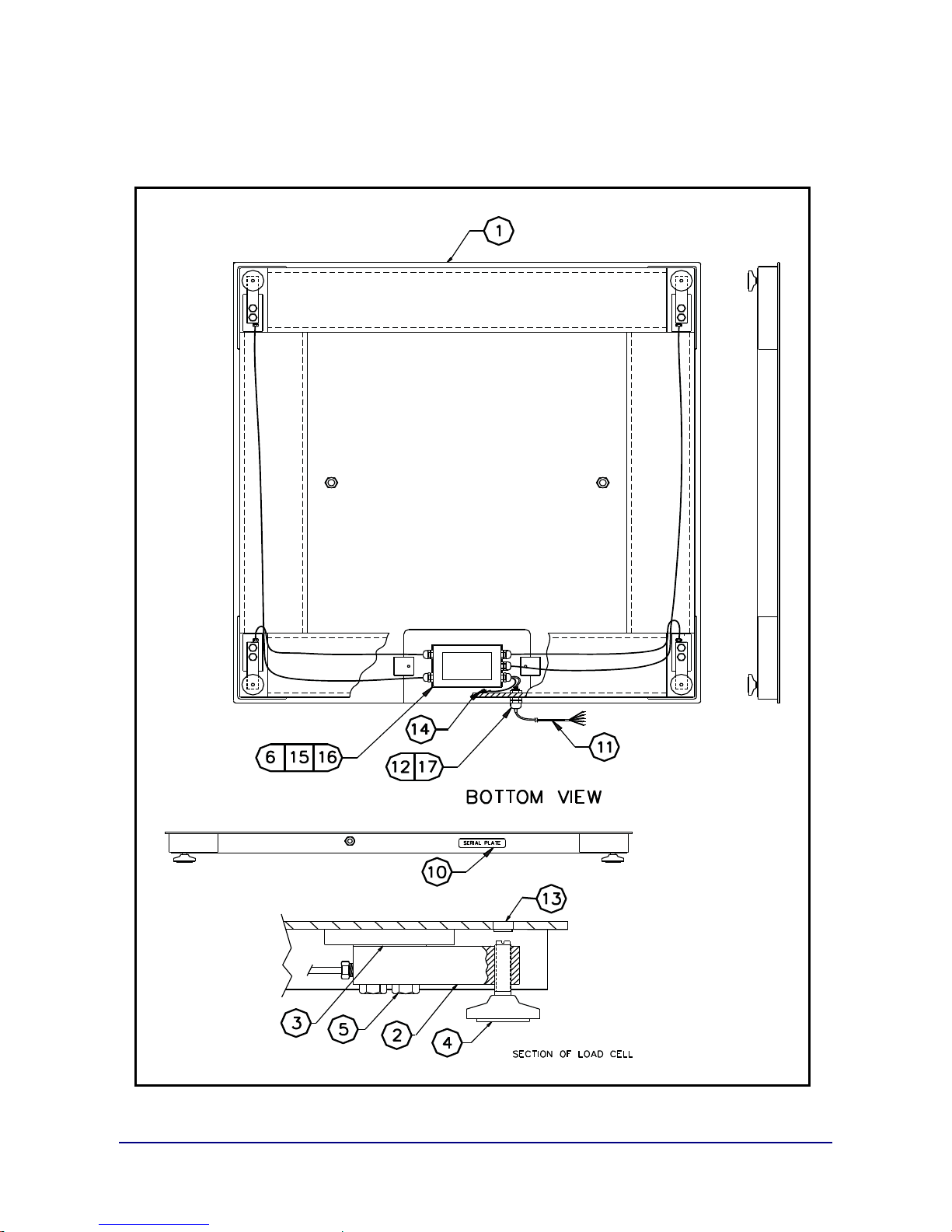
ITEM PART NO. DESCRIPTION MODELS
1 - - - - Platform Weldment - - - -
2 107003 Load Cell 1K, 2.5K
2 107004 Load Cell
2 107005 Load Cell
3 66754 Load Cell Shim ALL
4 63913 Foot Assembly ALL
5 54501 Load Cell Mounting Bolt, ½” – 20 x 1-3/4” ALL
6 67171M Analog Junction Box ALL
* 96141 PCB for Analog Junction Box ALL
11 12838 Cable Assembly ALL
12 17543 Liquid Tight Connector ALL
13 63586 Hole Plug, 5/8” ALL
14 54203 SS Hex Nut, 10-24 (for ground) ALL
15 14721 5” Velcro Loop (use with hook) ALL
16 14722 5” Velcro Hook (use with loop) ALL
17 11175 Rubber Bushing (for #11 connection) ALL
See
Appendix I for Analog Load Cell model numbers installed before 03/08.
5K
10K
NOTE: If the complete assembly is required (both the Junction Box and Board),
order part number 67171M as the new style replacement.
03/08 23 50612 Rev. 9
Page 24
Parts Diagram
Corner 2Corner 3
Corner 4
03/08 24 50612 Rev. 9
Corner 1
50612-2
Page 25
Appendix I: Load Cells Installed before 03/08
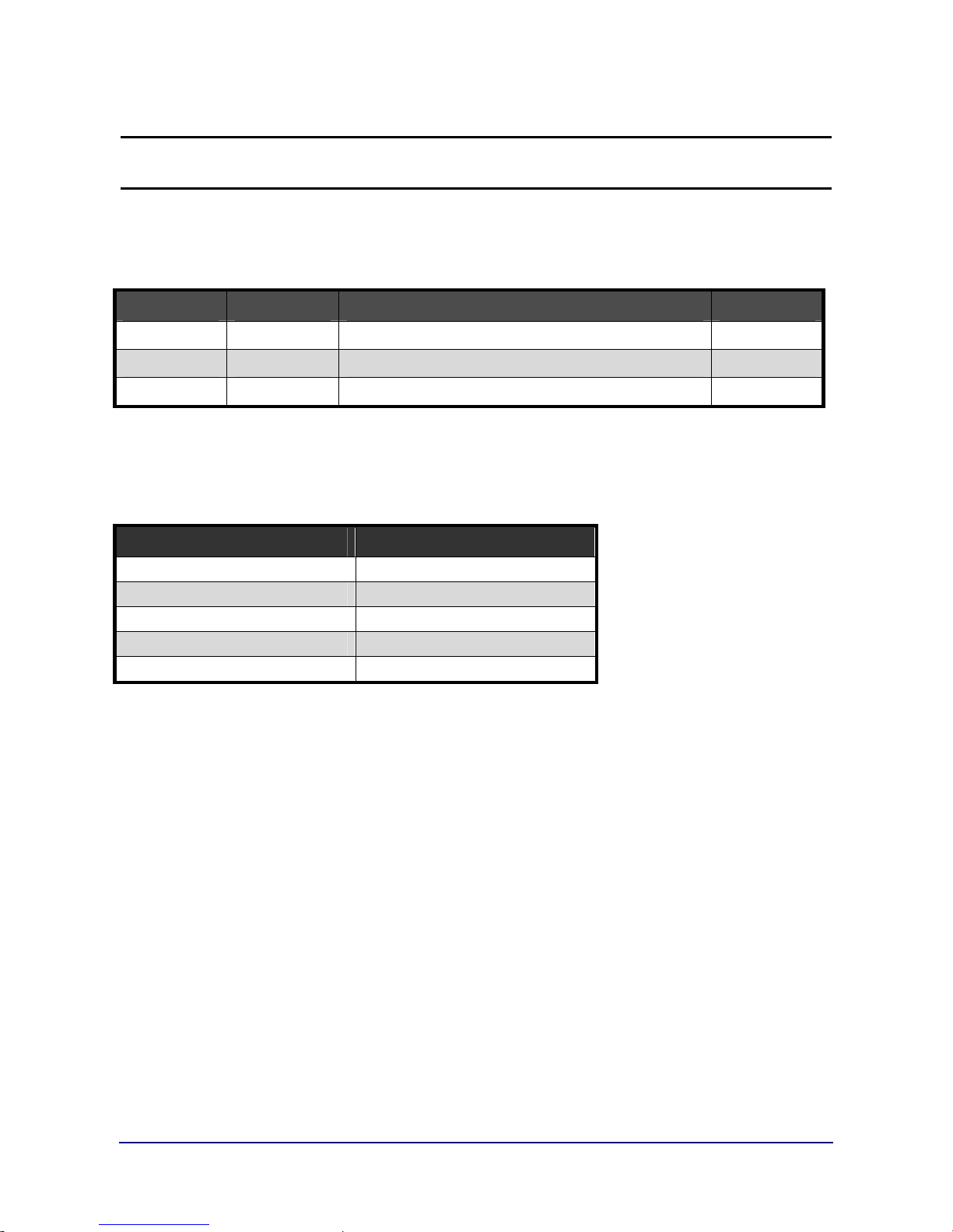
Listed below are the Load Cell Model Numbers installed before March 2008:
ITEM PART NO. DESCRIPTION MODELS
2 58925
2 12896
2 63593
Load Cell 1K, 2.5K
Load Cell 5K
Load Cell 10K
Shown below is the Load Cell wiring for models installed before January 2008:
WIRE COLOR FUNCTION
Black (─) Excitation
Red (+) Excitation
Yellow Shield
Green (+) Signal
White (─)Signal
03/08 25 50612 Rev. 9
Page 26

Appendix II: Model Matrix
PRODUCT NO. SIZE CAPACITY PLATFORM
WELDMENT
63606 3’ x 3”
63607 3’ x 3’
63608 4’ x 4’
63609 4’ x 4’
63610 4’ x 4’
63611 4’ x 5’
63612 4’ x 5’
63613 4’ x 6’
63614 4’ x 6’
63615 5’ x 5’
63616 5’ x 5’
63617 5’ x 7’
63618 5’ x 7’
1000 lbs 63489
2500 lbs 63489
2500 lbs 63491
5000 lbs 63491
10,000 lbs 63491
5000 lbs 63523
10,000 lbs 63523
5000 lbs 63525
10,000 lbs 63525
5000 lbs 63493
10,000 lbs 63493
5000 lbs 63495
10,000 lbs 63495
03/08 26 50612 Rev. 9
Page 27
Appendix III: Accessories
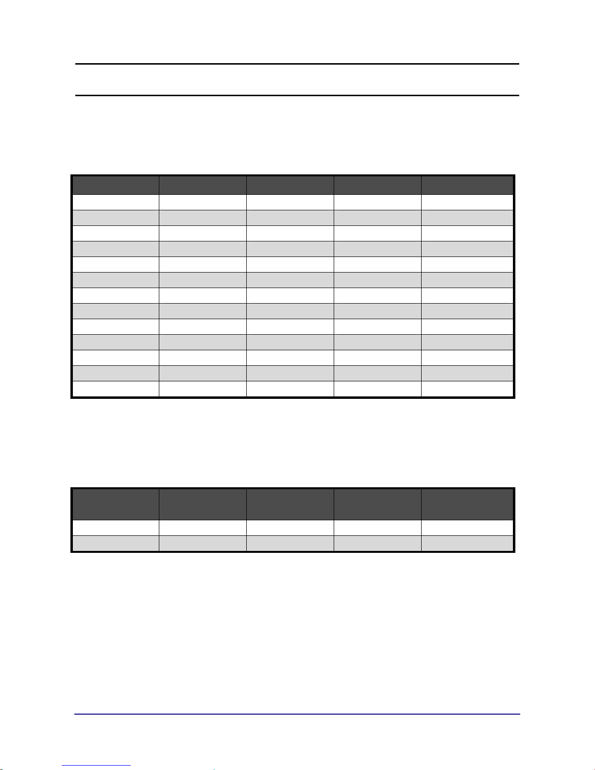
Ramps, Bumper Guards and Pit Frames
SIZE CAPACITY RAMP Bumper Guard PIT FRAME
3’ x 3”
3’ x 3’
4’ x 4’
4’ x 4’
4’ x 4’
4’ x 5’
4’ x 5’
4’ x 6’
4’ x 6’
5’ x 5’
5’ x 5’
5’ x 7’
5’ x 7’
1000 lbs 63751 (3’) 72198 (3’) 63757
2500 lbs 63751 (3’) 72198 (3’) 63757
2500 lbs 63753 (4’) 72194 (4’) 63759
5000 lbs 63753 (4’) 72194 (4’) 63759
10,000 lbs 63753 (4’) 72194 (4’) 63759
5000 lbs 63753 (4’) 72190 (5’) 63761
10,000 lbs 63753 (4’) 72190 (5’) 63761
5000 lbs 63753 (4’) 72196 (6’) 63763
10000 lbs 63753 (4’) 72196 (6’) 63763
5,000 lbs 63755 (5’) 72190 (5’) 63765
10000 lbs 63755 (5’) 72190 (5’) 63765
5,000 lbs 63755 (5’) 72192 (7’) 63767
10000 lbs 63755 (5’) 72192 (7’) 63767
Bolt-down Plates, Eyebolts and Hole Plugs
SIZE CAPACITY BOLT-DOWN
ALL
03/08 27 50612 Rev. 9
ALL 63777 (Set of 4) 70895 (2) 70896 (2)
EYEBOLTS EYEBOLTS
PLATES
63779 (Set of 2)
Page 28
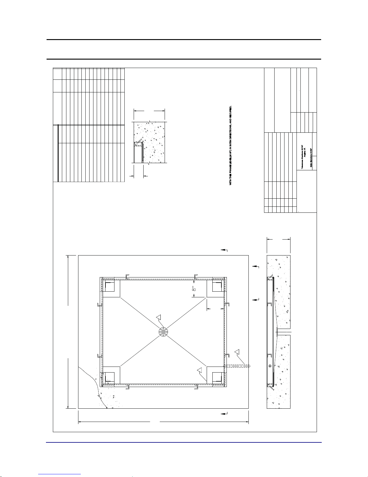
Appendix IV: Pit Frame Installation
8’
7’
7’
6’
6’
4’ X 4’
92850
6’
4’ X 5’
92851
6’7’7’
5’ X 5’
4’ x 6’
92853
92852
9’
5’ X 7’
8’ 10’
6’ x 8’
93108
2’-8"X5’-1" 7’-1"4’-8"
5’ 5’
A B
SIZE
3’ X 3’
PLATFORM
92849
OLD No.
2’-6" X 4’-2" 4’-6’ 6’-2"
9’ 9’
4’-6’ 7’-0"2’-6" X 5’-0"
7’ X 7’
4’ X 4’-6" 6’ 6’-6"
4’-6"
4’-6"
6’ x 6’ 8’ 8’
2’-6"x2’-6"
’
c
4’ X 3’ 6’ 5’
5’ X 10’ 7’ 12’
11"
1
of
1
material
sheet
1 - 10K, MS
Meridian, Mississippi
PIT INSTALLATION
FAIRBANKS SCALES
name
in. per ft.
scale
AEGIS INDUSTRIAL MILD STEEL
8/11/00
N/A
date
C-21896 MS
WAS_C142928/C142928-S
JSH
approved by
drawn by
checked by
63757
63759
MILD STEEL
ACC-1728 /
ACC-1729 /
MS MODEL / PART NO.
63761
63763
ACC-1730 /
ACC-1732 /
63767 92854
63765
ACC-1734 /
ACC-1736 /
79214
64062
ACC-1741 /
81242
81961
82908
89140
84080
107318
3 7/16"
B-B VIEW
REVISION
RELEASED
A PIT FRAME IS ONE-PIECE WELDED UNIT (NO FIELD WELDING REQUIRED).
1.
NOTE:
THE PIT DIMENSIONS ARE DETERMINED BY THE PIT FRAME ACCESSORIES.
A. AT LEAST 6" THICKNESS OF CONCRETE IS REQUIRED FOR PIT FLOOR
B. AT LEAST 11" CONCRETE FLOOR WITH MINIMUM 3" BOTTOM SLOPE(AS
2.
SHOWN) IS REQUIRED IF DRAINAGE IS REQUIRED FOR HOSTILE
TWO THIRDS OF THE TOTAL CAPACITY OF THE SCALE.
REQUIRED. THE CORNER PIER SHOULD BE DESIGNED TO SUPPORT AT LEAST
A SOIL BEARING PRESSURE OF AT LEAST 1,000 lbs PER SQUARE FT. IS
LOCATE CONDUIT TO MATCH HOLE LOCATION.
PIT FRAME IS ARRANGED WITH A 1 1/8" DIA. HOLE FOR CABLE EXIT.
A 3/4" DIA. CONDUIT FOR SCALE INTERFACE CABLE IS RECOMMENDED. THE
5.
4.
3.
INTERFACE CABLE THROUGH THE CONDUIT TO THE INSTRUMENT LOCATION,
AND LOWER THE PLATFORM ASSEMBLY INTO POSITION.
WHEN THE CONCRETE HAS REACHED A MINIMUM OF 2000 psi, PULL THE
FLOOR TO FORM SCALE PIT. IT IS RECOMMENEDED THAT f =3500 psi AND
CONCRETE IS FILLED IN AROUND THE OUTSIDE OF PIT FRAME AND PIT
3" TO 4" SLUMP CONCRETE BE USED.
6.
APPLICATION. A 4" DIA. DRAIN IS RECOMMENDED.
IN NON-HOSTILE APPLICATIONS.
A
TYP
8"
TYP
8"
2
B B
CHG’D SCALE FOOT LOCATORS
THE PLATFORM AND PIT COPING SHOULD BE 1/4" TO 3/8".
WITH THE SCALE IN THE PLACE, THE CLEARANCE AROUND THE EDGE OF
7.
DATE
8/11/00
10/23/02
BY
JSH
GAL
2
1
NO.
11"
FINISH
MATERIAL
3 place decimals:
Unless otherwise specified:
dimensions are in inches
2 place decimals:
without the prior written
transfered or repoduced
to be used, disclosed, copied,
Fairbanks Scales and is not
tial and is the property of
contained herein is confiden-
The material and information
permission of Fairbanks.
A (NARROW SIDE)
03/08 28 50612 Rev. 9
1K-10K
A-A VIEW
4
3
INSTALLATION OF PIT FRAME
POURED CONCRETE BASED ON THE SIZE
A
B
Page 29

Page 30

Floor Scale
SERVICE MANUAL
DOCUMENT 50612
Manufactured by Fancor, Inc.
 Loading...