

Page 1
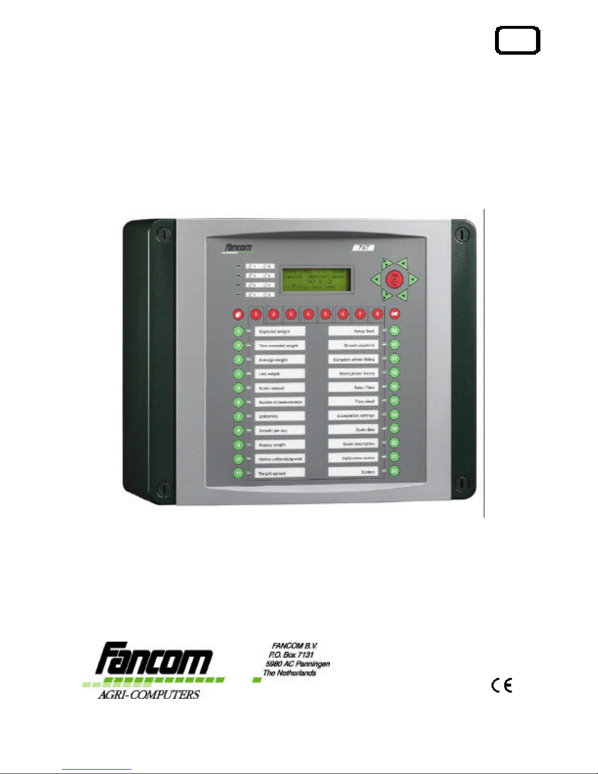
GB
747
USER
MANUAL
VERSION B2
Page 2

Fancom 747 Copyright
FANCOM B.V. Limited Warranty Statement
Fancom expressly warrants each new product manufactured by it to be free from defects in material or
workmanship for two years from the date of initial installation by or for the original purchaser, but in
no event shall such period be greater than two years and three months from the date of initial
shipment of the product from the manufacturer's facility. The following warranties are in lieu of any
and all representations and warranties, express or implied, including the implied warranties of
merchantability or fitness for a particular purpose, whether arising from statute, common law, custom
or otherwise. Fancom shall not be liable for any special, consequential or incidental damages resulting
from the use of any of the products or caused by any defect, failure or malfunction, whether a claim for
such damage is based upon warranty, contract, negligence or otherwise, and in no event shall Fancom
be liable for any damages in excess of the amount paid for the products. In the event a defect is found
by the Manufacturer to exist within this period, the Manufacturer will, at its option, (a) repair or
replace such product free of charge, F.O.B. the factory of manufacture, or (b) refund to the original
purchase price to the original purchaser, in lieu of such repair or replacement. Labor costs associated
with the replacement or repair of the product are not covered by the Manufacturer.
WARNING: Independent alarm installation
Like all mechanical and electronic devices, the Fancom Control Unit may fail. Thus, when the Fancom
Control Unit is controlling the environment for confined livestock, it is highly recommended by Fancom
that an independent alarm system be installed. The Fancom Control Unit does provide a connection
port designated for either make or break contact for the sounding of an alarm condition ( please refer
to installation guide for location ). Failure to comply with the above warning may result in loss of
product and/or profits, for which Fancom is not responsible or liable.
Always keep this manual by your computer
January, 2001
All rights reserved. Reproduction of any part of this manual in any form whatsoever without Fancom’s
express written permission is forbidden. The contents of this manual are subject to change without
notice. All efforts have been made to assure the accuracy of the contents of this manual. However,
should any errors be detected, Fancom would greatly appreciate being informed of them. The above
notwithstanding, Fancom can assume no responsibility for any errors in this manual or their
consequence.
Copyright 2003 Fancom B.V.
Panningen, the Netherlands
GB150103 MODIFICATIONS RESERVED
Art. Nr. A5911203
Page 3
Fancom 747 EC-Declaration of compliance
EC Declaration of compliance
Manufacturer : Fancom B.V.
Address : Industrieterrein 34
City : Panningen (the Netherlands)
hereby declares that the: 747
satisfies the following standards or other standard document(s):
Emission characteristics were assessed according to standards NEN-EN
50081-1. The susceptibility was established in accordance with the
requirements of the generic immunity standard NEN-EN 50082-2. The
low voltage guideline according to NEN-EN-IEC 60950.
Satisfies the conditions set out in:
1. The Low Voltage Guideline (Directive 73/23/EEG, as last amended by
the Directive 93/68/EEG).
2. The EMC Guideline (Directive 89/336/EEG, as last amended by the
Directives 92/31/EEG and 93/68/EEG).
Place: Panningen Date: 15-01-2003
(Signature) (Signature)
(Name of the signatory 1)
Math Stammen
(Name of the signatory 2)
Wout Hoolboom
(Occupation of the signatory 1)
Research manager
(Occupation of the signatory 2)
Project Manager feeding systems
Page 4

Fancom 747 Table of contents
Table of contents
About this manual
1. Introduction .....................................................................................1
2. Safety instructions and warnings ......................................................2
3. Working...........................................................................................3
4. Operation.........................................................................................5
4.1 Front........................................................................................5
4.2 Display (A)................................................................................6
4.3 Keyboard (B) .............................................................................6
4.4 Index, scale keys and alarm (C)..................................................9
4.5 Function keys (D) .................................................................. 10
4.6 LEDs (E) ................................................................................. 11
5. Calibrating scales ........................................................................... 12
6. Settings ......................................................................................... 14
6.1 Checking date and time ........................................................... 14
6.2 Way of measuring and time clock............................................. 15
6.3 Acceptation limits.................................................................... 16
6.4 Growth standard ..................................................................... 20
6.5 Scale data ............................................................................... 22
6.6 House and scale description ..................................................... 23
6.7 Setup flock.............................................................................. 25
7. Printing results.............................................................................. 26
7.1 General................................................................................... 26
7.2 Complete printer listing ........................................................... 26
7.3 Short printer listing ................................................................ 27
8. Data presentation........................................................................... 29
8.1 Actual data ............................................................................. 29
8.2 Data record ............................................................................. 33
8.3 Weight spread......................................................................... 35
9. Alarm............................................................................................ 36
9.1 Switching the alarm off ........................................................... 36
9.2 Possible alarms....................................................................... 37
10. Password...................................................................................... 38
APPENDIX 1: Menu overview
APPENDIX 2: Installation report
Page 5
Fancom 747 About this manual
About this manual
This manual aims to supply the user with the information necessary for a
step by step insight into the working and operation of the computer. Read
this manual carefully chapter by chapter. After the manual has been read,
data can be entered in the computer.
This manual has been written by Fancom for the computer user. An
installation manual is also available for the installer.
If you have any questions regarding the computer, please do not hesitate
to contact your Fancom dealer.
The following symbols are used in this manual:
+
Suggestions, advice and notes with additional information.
Caution
The product could be damaged, if the procedures are not followed
carefully.
Caution
Life threatening situation, if the procedures are not followed
carefully.
Page 6

Fancom 747 1. Introduction
1
1. Introduction
Fancom has developed the 747 live bird weighing system for continuous
poultry weighing. The weighing system comprises one poultry weighing
computer and from one up to maximum eight electronic weighing scales.
Communication
It is possible to communicate with the 747 computer via a PC. Via
modems even at great distances.
The RS232C serial port (PC-interface) or the Fancom network (FNet) can
be used for communication. If the RS232C port is not used for
communication, it can be used to print overviews.
Using the Fancom F-Central program on the PC the increasing growth
line of the animals can be shown in graph form.
Page 7
Fancom 747 2. Safety instructions and warnings
2
2. Safety instructions and warnings
Read the safety instructions carefully before operating the system.
The installation of the computer and trouble shooting must be carried out
by an authorized technician/installer, according to the prevailing
standards.
Caution
1. Check your computer regularly for correct functioning. It is an
electronic apparatus and should therefore give an alert during any
system failures. Fancom has done everything electronically possible to
ensure that an alarm is given during any such failure. Unfortunately,
this cannot be 100% guaranteed because not all circumstances are
under Fancom’s control.
2. Fancom takes no responsibility for any possible damage as a result of
incorrect settings and a non- or partially functioning installation.
3. Ask your installer if the alarm contacts of each computer have been
connected to a separate alarm system circuitry.
4. Check the computer regularly for possible damage. Any damage
should directly be reported to your installer.
A damaged computer could be dangerous!
5. Do not use running water (high pressure cleaners) to clean your
computer.
The computer is water resistant, not waterproof!
6. Important
Do not switch off the computer when houses are unoccupied; this is
to protect the computer against condensation.
Page 8
Fancom 747 3. Working
3
3. Working
The 747 weighs individual animals, independent of the number of animals
on the scales at any one time. The amount of droppings left on the scales
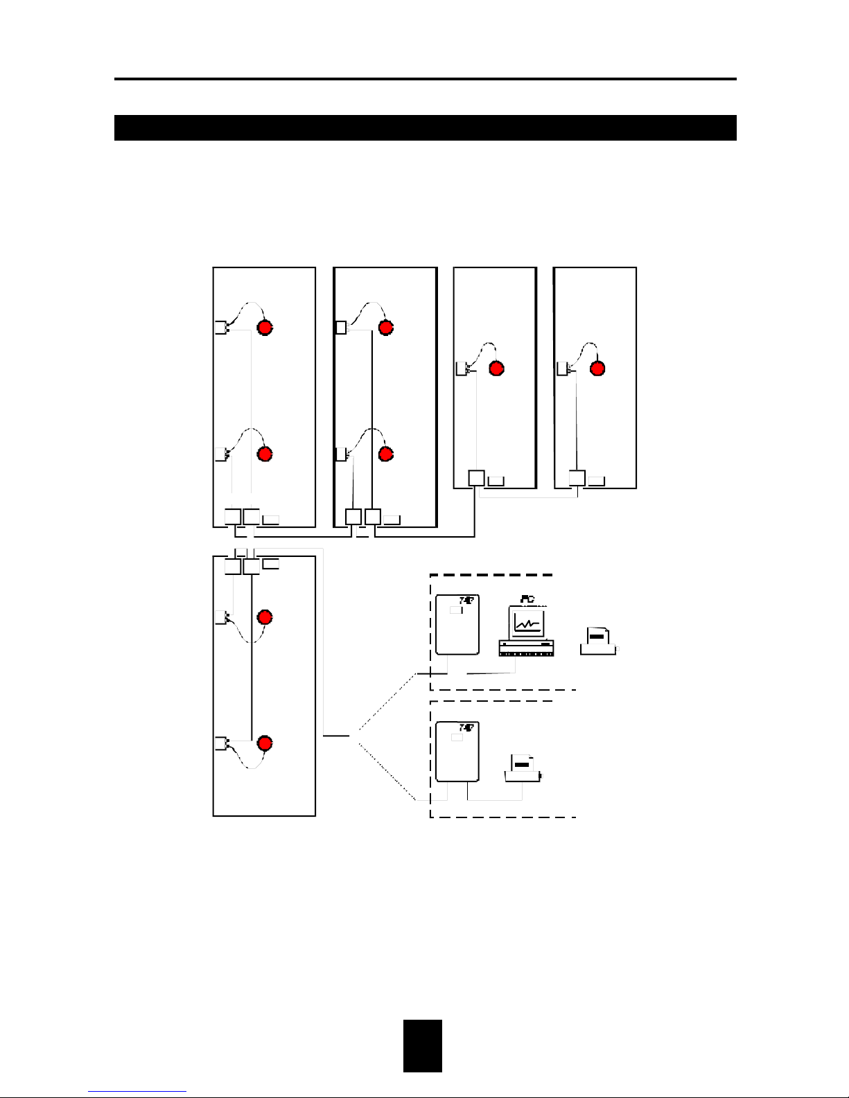
is ignored. Fig. 1 shows an example of a poultry weighing system:
Fig. 1: Principle diagram (e.g. three houses each with two weighing scales and two
houses each with a single weighing scale).
HOUSE 2
HOUSE 3 HOUSE 4 HOUSE 5
HOUSE 1
OFFICE
OFFICE
Printer
Printer
I/O-Net
ILM
PS.24
CBox
Scale
Page 9

Fancom 747 3. Working
4
The Fancom weighing system consists of a computer and a maximum of
eight weighing scales. The scales are connected to the computer. The
computer can be connected to a PC or a printer.
For example, eight scales can be placed in one flock or one scale in each of
eight individual flocks. The age of the flock can be entered separately for
each house.
The scales are movable; weighing can be carried out at any required
location in the house. The system can be prepared for use quickly and
easily.
The easy to read 4 × 20 character display clearly shows all the
information. Not only in figures, but also with an explanatory text.
The computer collects data of the individual animal weights per day,
reviews overviews up to 365 days back and weight spread up to 16 days
back. The system provides the information on print lists, allowing the
animals’ growth progress to be clearly followed.
Page 10
Fancom 747 4. Operation
5
4. Operation
4.1 Front
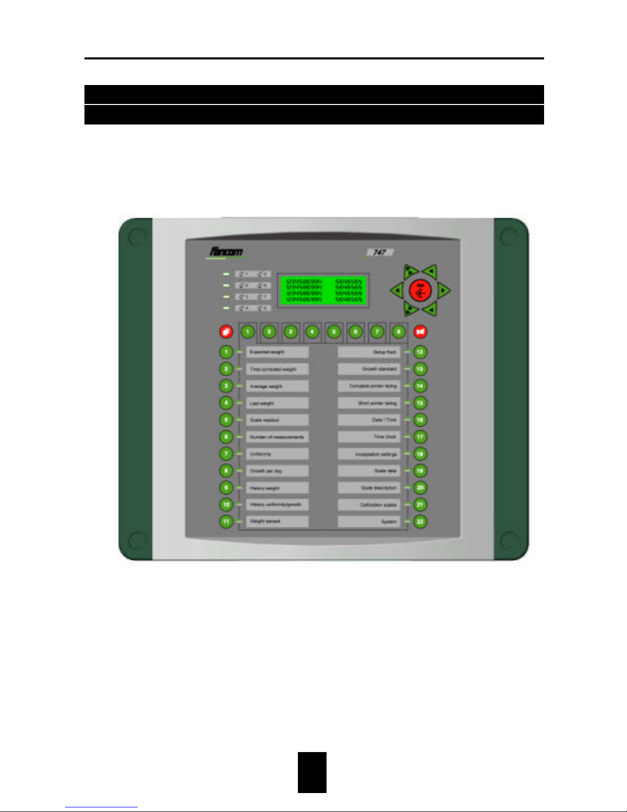
In order to operate the computer, it is necessary to know the functions of
the various keys and indication lights (LEDs). Fancom divides the front
into five parts (A, B, C, D and E).
Fig. 2. Front 747
B
C
Page 11
Fancom 747 4. Operation
6
4.2 Display (A)
The front of the 747 has an illuminated display consisting of 4 lines, each
with 20 characters. The display shows the most recent weight measured
by the computer, or the setting to be changed. A letter (or a figure) will
always flash in the display to indicate where the setting can be changed.
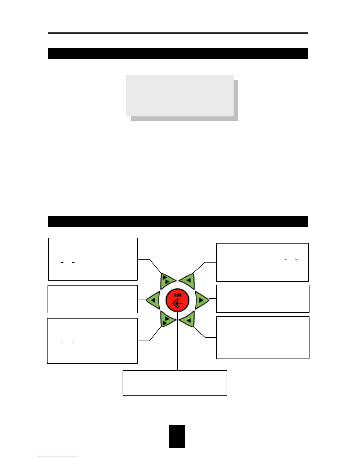
4.3 Keyboard (B)
Expected weight
1567 1583 1571
0 0 0
0 0
♦ During changes increase value of
flashing position by 1 (25à26).
♦ During text changes select the
next character from the group.
♦ During changes cursor to the
right.
♦ Open menu.
♦ During changes decrease value of
flashing position by 1 (25à24).
♦ During text changes select the
previous character from the
group.
♦ During changes increase value
in front of the flashing position
(25à35).
♦ During text changes select the
next group of characters.
♦ During changes cursor to the
left.
♦ Return to previous menu.
♦ During changes decrease value
in front of the flashing position
(25à15).
♦ During text changes select the
previous group of characters.
To access and quit the modify procedure:
always press this key before and after a
value is entered.
Page 12
Fancom 747 4. Operation
7
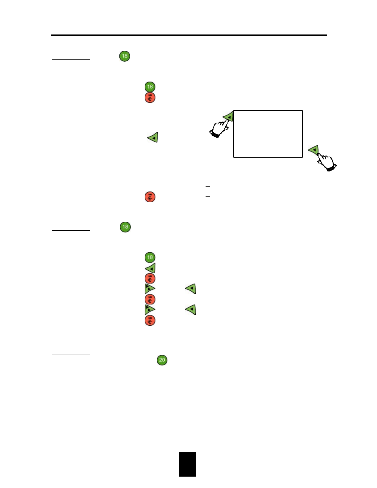
Example 1: At
Acceptation settings change the way of measuring
from ON-OFF into STEP.ON.
1. Press
.
2. Press
.
3. Select way of
measuring from the
table
(Press
2×).
4. Press
.
Way of meas. ON-OFF
Way of meas. ON-OFF
Way of meas. STEP.ON
Way of meas. STEP.ON
Example 2: At
Acceptation settings change the lower and upper
limit percentages from 10% to 25%.
1. Press
.
2. Press
.
3. Press
.
4. Press
1× and 5×.
5. Press
.
6. Press
1× and 5×.
7. Press
.
Lower limit(%) 10
Lower limit(%) 10
Lower limit(%) 25
Upper limit(%) 10
Upper limit(%) 25
Lower limit(%) 25
Example 3: This example shows how to change text, for example, at
function key
Scale description à 1. Scale description
à Scale name.
BLOCK.
ON-OFF
STEP.OFF
STEP.ON
Page 13
Fancom 747
4. Operation
8
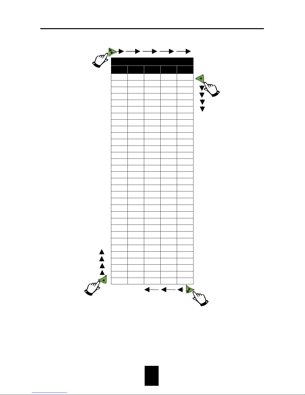
Groups
1 2 3 4 5*
0Aa
←
!1Bbü
"2Ccé
#3Ddä
$4EeÀ
5Ff c
&6Gg|
'7Hhè
(8Iiö
)9Jjû
*:Kky
+;Llo
,< ñ
-=Nna
.>Ooe
/?Ppz
Qq Rr
α
Ss
β
Tt
π
Uu
Σ
Vv
µ
Ω
Xx
∞
Yy
•
Zz
ε
[{
°
\|
]}
^
→
`
The characters from group five depend on the language.
Using the F-Central program some characters on the PC-screen may differ.
!
select next group
Select next character
from group
select previous
character from group
select previous group
Page 14
Fancom 747 4. Operation
9
4.4 Index, scale keys and alarm (C)
If there is more data of the same type, this key can be used to
jump to a higher or lower number.
Example :
On day 42 the weight of day 22 is required.
1. Press
History weight.
2. Press
.
3. Enter the number of days back from the current day (4222=20); press
2×, then
1×).
4. Press
.
Instead of
, keys
and
can also be used to increase/ decrease
the number.
Scale keys
Use these keys to select the scale for which data is to be read out and/or
changed. A built-in light in the key will indicate which scale has been
selected. If data concerns all the scales connected, no light will illuminate.
This applies to keys
thru
and
thru
.
If there is an alarm situation, further information about the
alarm can be found under this key. Table 1 shows the meaning of
the values which can be set and read out at the alarm key.
Page 15

Fancom 747 4. Operation
10
Table 1: Alarm values
Value Situation Explanation
0 Alarm stand by There is no alarm.
1 Alarm test Set alarm to 1 to test it; then reset alarm to
stand by by entering the value 0.
5 Alarm
Cancelled
There was an alarm, which has been
cancelled. The computer switches off the
alarm, but the alarm code remains visible.
6 Silent alarm Alarm message shown on display only.
7 Alarm
temporarily off
Set value to 7 to temporarily switch off the
current alarm. When the alarm situation
has been cancelled, this value will
automatically become 0 again. Always
check that the value has reverted to 0.
8, 9 Alarm blocked Set the value to 8 or 9 to switch off the
alarm entirely. Only do this when houses
are unoccupied. Do not forget to reset value
to 0
10 Alarm The type of alarm is shown on the display.
4.5 Function keys (D)
On the front of the computer are 22 function keys. Select a function key by
pressing it. The display will show data relating to this key. A light in the
function key indicates which key has been selected.
Page 16
Fancom 747 4. Operation
11
4.6 LEDs (E)
There are four LEDs. Each time the computer
accepts (registers) a weight, the scale LED
concerned will light up.
Example :
The second LED lights up. This means that the
computer has just accepted a weight on scale 2 or
scale 6.
+
Fancom shows the keys as a symbol in this manual. These keys can
be found in Fig. 2 and on the front of the computer.
Page 17

Fancom 747 5. Calibrating scales
12
5. Calibrating scales
In order for the weighing computer to function properly, the scales must
be calibrated. In practice, the scales will generally be calibrated at the
beginning of a new flock cycle.
1. Determination of the zero
+
Ensure there is nothing on the scales.
1. Press
Calibration scales.
2. Select the scale to be calibrated, e.g. Scale 1.
The following text will appear on the display:
3. Set Agreed? to YES. The computer will then automatically change
YES into NO again.
Setting zero:
Agreed? NO
Weight 0.000
>>
Page 18
Fancom 747 5. Calibrating scales
13
2. Entering the standard weight
+
Ensure there is nothing on the scales
4. Press
. The following text will appear on the display:
5. Enter the standard weight value at Enter weight (e.g. 3000g).
6. Place the standard weight on the scale.
7. Set Agreed? to YES. The computer will then automatically change
YES into NO again.
8. Calibr. date shows the date of the last calibration.
Scale 1 has been calibrated. Repeat this procedure for the remaining scales
which are connected.
Enter weight: 3000
Agreed? NO
Weight 0
>>
Calibr.date 12-03-99
Page 19

Fancom 747 6. Settings
14
6. Settings
6.1 Checking date and time
In order for the computer to function properly, the system date and time
must be correct. Before values are entered, check the system date and
time.
Method
1. Press key
Date/time.
The following text will appear on the display:
2. Correct date and/or time, if necessary (see section 4.3).
Date 12-03-99
Time 10:46
Page 20

Fancom 747 6. Settings
15
6.2 Way of measuring and time clock
Fancom delivers the weighing computer with factory settings. These can
be changed, but it is not strictly necessary.
Method
1. Press key
Acceptation settings.
The following text will appear on the display:
2. Set the required way of measuring at Way of measuring.
There are four possibilities:
BLOCKED The weighing system does not register any weights.
By placing this setting to blocked, unnecessary alarms
can be prevented if the scales are faulty.
ON-OFF The system registers the weight at the moment the
animal steps onto the scale and the moment it steps off
the scale.
STEP.OFF The system registers the weight at the moment the
animal steps off the scale.
STEP.ON The system registers the weight at the moment the
animal steps onto the scale.
Way of meas. ON-OFF
Lower limit(%) 30
Upper limit(%) 30
>>
Page 21
Fancom 747 6. Settings
16
Entering a time clock
1. Press key
Clock.
The following text will appear on the display:
2. At Time clock enter the times between which the computer must
register measurements.
3. Clock shows if the computer is currently registering weights
(ACTIVE) or not (NON-ACT.).
6.3 Acceptation limits
Fancom delivers the weighing computer with factory settings. These can
be changed, but it is not strictly necessary.
Method
1. Press key
Acceptation settings.
The following text will appear on the display:
2. At Lower limit (%) and Upper limit (%) enter the limits in
percentages, between which the computer must accept
measurements.
Timeclock 0:00-24:00
Clock ACTIVE
Way of meas. ON-OFF
Lower limit(%) 30
Upper limit(%) 30
>>
Page 22
Fancom 747 6. Settings
17
Acceptation weight and calculated acceptation limits
1. Press key
Acceptation settings.
2. Press
2×. The following text will appear on the display:
Acc. Weight shows the theoretic weight. The computer calculates this
weight from the entered and assigned growth standard. If no growth
standard has been entered and assigned, the acceptation weight can be
entered here directly.
The computer calculates the acceptation lower and upper limits based on
the acceptation weight and the limits entered in percentages.
Acc.lower limit 700
Acc.weight 1000
Acc.upper limit 1300
>>
2×
Page 23
Fancom 747 6. Settings
18
Curve
In houses with heavier animals, a high occupancy and mixed males and
females, it is advisable to enter the upper and lower limits in the computer
via a curve. The heavier the animals become and the higher the
occupancy, the higher the lower limit should be. The lighter, female
animals will be proportionally more frequently on the scales. By setting
Lower% lower, the computer will refuse to accept a number of the lighter
weights. This will not influence the weight spread.
1. Press
Acceptation settings, then
3×.
The following text will appear on the display:
2. At Curve enter whether the computer should take the lower and
upper limit from the curve.
3. Use
to select the bending point (max. 10 bending points).
4. Enter the day number and the lower and upper limit corresponding to
this bending point.
5. Make these settings for the other bending points in this curve.
Example : Lower limit (%) 30%
Upper limit (%) 30%
Acceptation weight (calculated) 1000g
The computer calculates the acceptation lower
and upper limit:
Acc. lower limit 1000g - 30% = 700g
Acc. upper limit 1000g + 30% = 1300g
Uniformity calculation
Curve YES
Day_1 Lower% Upper%
1 30 30
3×
Page 24
Fancom 747 6. Settings
19
1. Press key
Acceptation settings.
2. Press
4×. The following text will appear on the display:
Enter if the computer must calculate the uniformity over 10% or 15%.
This depends on how the integration is calculated.
Offset acceptation weight
1. Press key
Acceptation settings.
2. Press
5×. The following text will appear on the display:
After changing the acceptation weight (parent stock and rearers), the
corrected amount appears as an offset value at Offs.Acc.Weight.
With parent stock the upper and lower limit of the acceptation weight of
males and females is protected against overlaps.
Offs.Acc.Weight 0
5×
Uniformity
calculation over 10
>>
4×
Page 25

Fancom 747 6. Settings
20
6.4 Growth standard
The 747 weighing computer can be used to weigh broilers, turkeys,
animals for rearing and parent stock. At installation, the installer will
have set the 747 computer to suit the individual situation of the user.
Depending on the situation, the computer will use one or two growth
standards.
A growth standard is a table with the weights expected on fixed days. This
growth standard is available from your information service, feed supplier,
veterinary practice etc.
Fancom has entered the six following growth standards in the 747
computer at delivery:
1. Broilers
2. Turkey hens
3. Turkey cocks
4. Rearers
5. Parent stock hens
6. Parent stock cocks
The installer has set the growth standard for your situation (as a factory
setting below
System).
Parent stock
Two growth standards are important for parent stock: one for the female
parent stock and one for the males. In this case, a maximum of four scales
can be connected per computer. There are two readouts per scale: one for
hen data and one for cock data. The readout is as follows:
Page 26
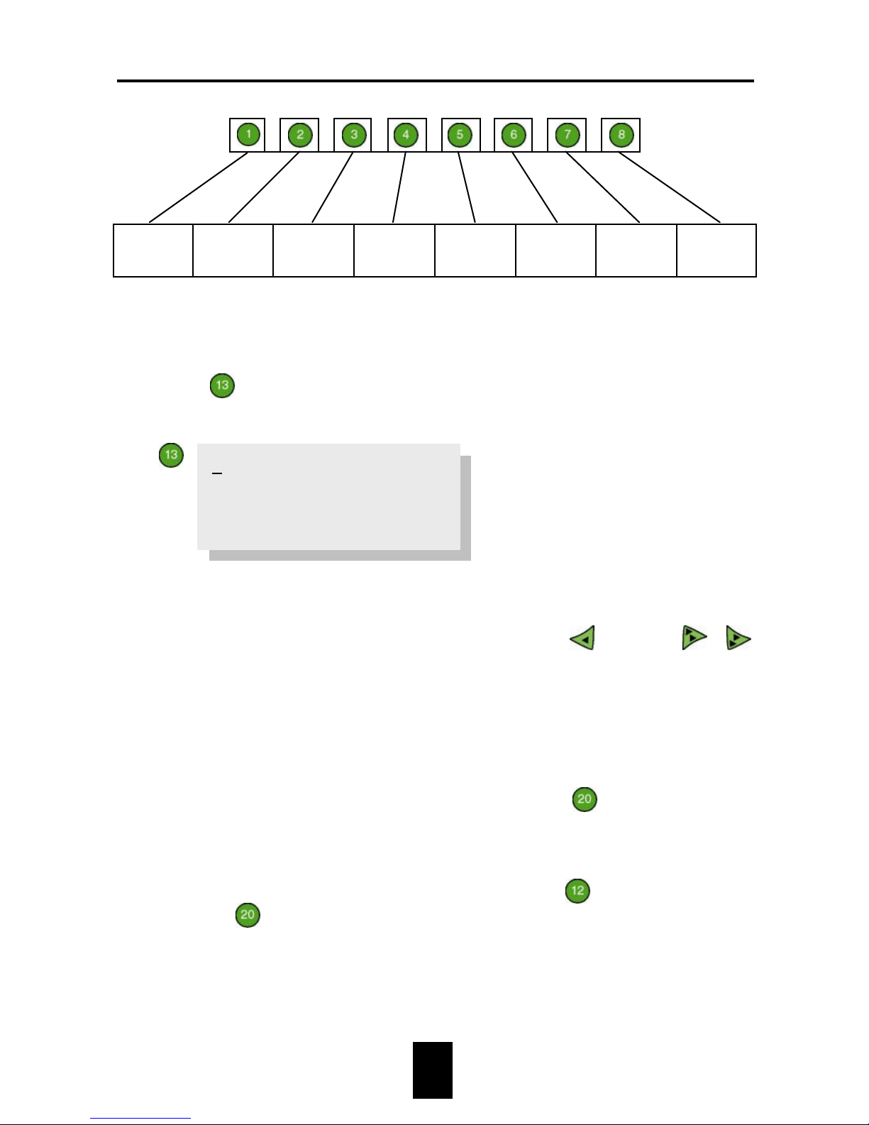
Fancom 747 6. Settings
21
Hen
data
scale 1
Cock
data
scale 1
Hen
data
scale 2
Cock
data
scale 2
Hen
data
scale 3
Cock
data
scale 3
Hen
data
scale 4
Cock
data
scale 4
The name and values of the growth standard can be changed:
1. Press
Growth standard. The following text will appear on the
display:
The first line shows the name of the growth standard (maximum 10
characters). This name can be changed on the last line (see example 3 in
section 4.3). The last line can be reached by pressing
20×. Use
/
to examine the next/previous growth standard.
2. Enter the day number and the weight expected on that day for each
bending point (max. 20 bending points).
+
The desired growth standard can be selected at
Scale description
à 1. Scale description à Growth std.
If growth standards are not used, an Initial weight can be set per
scale. This initial weight is entered at key
Setup flock. The
setting
Scale description à 1. Scale description à Growth std.
is on NONE.
Grth.std –1 BROILERS
1. Day 1 Wght. 40
2. Day 7 Wght. 154
3. Day 14 Wght. 363
Page 27
Fancom 747 6. Settings
22
6.5 Scale data
After the settings have been made at key
Setup flock, the computer
will automatically fill in the scale data.
Method
1. Press
Scale data.
The following text will appear on the display:
2. Enter the Flock number (e.g. 0299 = 2nd flock in 1999). This flock
number is normally entered at option
Setup flock (see section 6.7).
The computer also processes this flock number at this option.
3. Days shows the age of the flock (see section 6.7).
4. Std/Init.wght. shows the initial weight that has been entered at
Setup flock (if growth standards are not used).
If the growth standards are used, the weight determined by the
computer from the assigned growth standard will be shown here.
5. Setup date shows the date the animals entered the house. The
computer automatically calculates this date after the flock has been
setup using key
Setup flock.
Flock number 0299
Days 1
Std/Init.wght. 40
Setup date 12-03-99
Page 28
Fancom 747 6. Settings
23
6.6 House and scale description
The house and scale description only has to be entered once. If more than
one cycle has already been completed, continue reading from section 6.7.
Entering a house name
1. Select
Scale description à 2. House description.
The following text will appear on the display:
2. Enter the name of this house at Name_1 (see example 3 in section
4.3).
3. Repeat this for the other houses.
Selecting a house name
1. Select
Scale description à 1. Scale description.
The following text will appear on the display:
2. Select the house where this scale is located at House (see example 2
in section 4.3).
>>House description
Name_1 HOUSE 1
>>Scale description
House HOUSE 1
Scale name SCALE 1
Growth.std BROILERS
Page 29
Fancom 747 6. Settings
24
Entering a scale name
1. Select
Scale description à 1. Scale description.
2. Enter the name of this scale at Scale name (see example 3 in section
4.3).
3. Repeat this for the other scales in this house.
Entering a growth standard number
1. Select
Scale description à 1. Scale description.
2. At Growth std. select the growth standard applying to this scale.
Once these settings have been made, the settings can be made next time a
flock is setup at key
Setup flock. The settings are made here per
house.
At installation, the installer has assigned the scales to a house. The
settings apply for all the scales in that house.
Page 30
Fancom 747 6. Settings
25
6.7 Setup flock
At the beginning of a new cycle, only the following settings have to be
made. These settings are made per house. The computer will do the rest.
Method
1. Press
Setup flock.
The following text will appear on the display:
2. At House enter the number of the house where the flock will be setup.
The settings made here automatically apply to all the scales in this
house (e.g. house 1).
3. At Day enter the age of the flock. The computer uses this setting to
determine the actual position in the growth standard.
4. At Flock number enter the number of the new flock (e.g. 0299 = 2nd
flock in 1999).
5. If the growth standard is not used for this house, enter the average
animal weight at Initial wght.
6. Set Agreed? to YES.
As soon as the settings have been stored in the computer’s memory, it will
change House and Day into 0 again, Agreed? into NO, and will process
the number of days and flock number entered at key
Scale data.
+
If Agreed? is set to YES at setup, the computer will erase the
administrative data relating to the previous flock for all the scales in
this house.
House 1 Day 1
Flock number 0299
Initial wght. 0
Agreed? NO
Page 31
Fancom 747 7. Printing results
26
7. Printing results
7.1 General
Once all the settings and calibrations have been completed and the flock
has been in the house for a certain period of time, the growth results can
be inspected. The computer is able to print out all the results for an entire
house or scale (from the setup date). If the results of a certain period only
are required, select the short scale or house listing.
7.2 Complete printer listing
1. Press
Complete printer listing.
The following text will appear on the display:
2. Press
.
3. Choose between scale overview (
) or house overview ( ).
4. Enter the number of the house or scale for which the results are to be
printed.
5. Set Print? to YES.
>Complete listing
SCALE Nr. 2
Print ? NO
Page 32
Fancom 747 7. Printing results
27
7.3 Short printer listing
1. Press
Short printer listing.
The following text will appear on the display:
2. Press
then choose between scale overview (
) and house
overview ( ).
3. Enter the number of the house or scale for which the results are to be
printed.
4. Enter the number of days for which a short printer listing is required
(e.g. 10 days). If 0 is entered here, the computer will print out all the
data for this house.
5. Set Print? to YES.
An example follows of a house and a scale printer listing.
***FANCOM*** HOUSE OVERVIEW House 1 House 1 Date 01-
¡
Flock nr
:0299
Day nr.
:40
Setup
22-01-99
¡
¡
Scale
:1
Middle
¡
Scale
:2
Front
¡ ¡
Day
Number
Average
End
Gr.St
Growth
Unifor
¡
40
279
1720
1738
17905058¡39
587
1670
1690
17275160¡38
645
1619
1640
16565659¡37
789
1563
1585
15995257¡36
831
1511
1533
15494561¡35
789
1466
1488
15015060¡..
....
....
....
........¡ 1
3512
43
52
45
3
71
Printer listing 1: Complete overview of house 1
>Short listing
SCALE Nr. 2
Nr. of days 10
Print? NO
Page 33

Fancom 747 7. Printing results
28
***FANCOM*** SCALE OVERVIEW Scale 1 Middle Date 01-
¡
Flock nr.
:0299
Day nr.
:40
Setup date:
22-01-99
¡
¡
House
:1
House
:1
¡
¡
Day
Number
Average
End
Gr.St
Growth
Uniform.
¡
40
140
1725
1743
17905555¡39
290
1670
1691
17275159¡38
331
1619
1639
16565962¡37
339
1560
1583
15994963¡36
412
1511
1532
15494565¡35
359
1466
1487
15016063¡..
....
....
....
........¡ 1
1712
43
51
45 270
¡
Printer listing 2: Complete listing of scale 1
Page 34

Fancom 747 8. Data presentation
29
8. Data presentation
8.1 Actual data
The first eight function keys show an overview of the actual weighing
situation per scale. These displays appear as follows:
Readout of expected weight
The expected computer calculated weights per scale are shown. When
calculating, the computer takes the weight spread within the flock into
account, for example. The computer expects (calculates) the actual weights
in the house. The weights shown are as close as possible to the actual
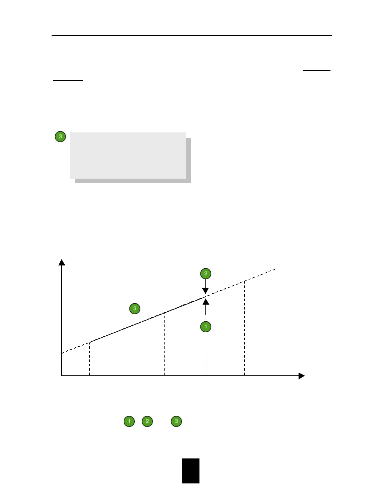
weights at that moment (see Fig. 3).
Readout of time corrected weight
The computer calculates the average weight per scale based on all the
measurements that have been accepted at that scale today ( ).
Expected weight
1567 1583 1571
0 0 0
0 0
Scale 1 Scale 2 Scale 3
Scale 4 Scale 5 Scale 6
Scale 7 Scale 8
Time corr. weight
1580 1578 1620
0 0 0
0 0
Page 35
Fancom 747 8. Data presentation
30
Growth continues throughout the day. The computer will carry out
another correction in order to calculate the average weight at this
moment. This results in the time corrected weight (see Fig. 3).
Readout of average weight
The average weights per scale are shown. These weights have been
calculated by the computer using all the measurements accepted today.
The computer does not take growth throughout the day into account in
this calculation (see Fig. 3).
Fig. 3: Graph of keys
,
and .
Average weight
1535 1520 1589
0 0 0
0 0
Expected weight
using formula
Time corrected
weight
Average weight
0:00
Current time
12:00
24:00
Weight
Time
Page 36

Fancom 747 8. Data presentation
31
Readout of last weight
Readout of the last weights accepted at scales connected.
Readout of scales
Direct readout of the current weight on the scales connected.
Readout of number of measurements
Readout of the number of measurements accepted by the computer at all
the scales today.
Last weight
1501 1498 1538
0 0 0
0 0
Scale readout
1950 1511 0
0 0 0
0 0
Nr. of measurements
775 772 814
0 0 0
0 0
Page 37
Fancom 747 8. Data presentation
32
Readout of uniformity % and Co-Variance (CV)
The uniformity percentage, the percentage of all the measurements that
are within 10% of the average weight, is shown per scale.
The co-variance (CV) calculated by computer per scale is also shown. This
statistical value is always calculated, but is only of importance with
parent stock.
Readout of growth per day
Readout of the average growth in grams per animal per scale today.
Uniformity
75 68 71
0 0 0
0 0
CV
10.0 9.8 10.1
0.0 0.0 0.0
Growth per day
50 52 51
0 0 0
0 0
Page 38
Fancom 747 8. Data presentation
33
8.2 Data record
Certain data can be reviewed up to 365 days back.
Readout of stored weights
1. Press
History weight.
The following text will appear on the display:
2. Select the scale for which stored data is to be readout (see section 4.4).
3. Use
to select the day for which this data is to be viewed (see
section 4.4).
4. Average wght. shows the average weight. The computer has
calculated this average using all the weights registered that day.
5. Growth std. shows the theoretic weight from the growth standard, as
it should be on that day.
6. End of day shows the value of the expected weight at the end of that
day.
History Day 35
Average wght 1535
Growth std. 1567
End of day 1561
Page 39
Fancom 747 8. Data presentation
34
Readout of uniformity and growth
1. Press
History uniformity/growth
The following text will appear on the display:
2. Select the scale for which stored data is to be readout (see section 4.4).
3. Use
to select the day for which this data is to be viewed (see
section 4.4).
4. Growth/day shows the average animal growth in grams that day.
5. CV shows the computer calculated co-variance that day.
6. Unif. shows the percentage of all the measurements that were within
10% of the average weight that day.
7. Measurements shows the number of measurements that have been
accepted by the computer at all the scales that day.
History Day 35
Growth/day 53
CV 10.0 Unif. 72
Measurements 182
Page 40
Fancom 747 8. Data presentation
35
8.3 Weight spread
The spread of accepted weights per scale on a certain day can be shown.
1. Press
Weight spread
The following values will appear on the display (example):
The computer divides the accepted weights into 25 groups. The number of
measurements accepted by the computer on the day entered is shown
behind each group.
Histogram Day 35
à1060 3
1060à1100 8
1100à1140 12
1140à1180 36
1180à1220 43
1220à1260 48
1260à1300 56
1300à1340 56
1340à1380 50
1380à1420 38
1420à1460 19
1460à1500 7
1500à1540 15
1540à1580 12
1580à1140 12
1620à1140 12
1660à1140 12
1700à1140 12
1740à1140 12
1780à1820 42
1820à1860 40
1860à1900 27
1900à1940 18
1940à1980 7
1980à 6
Page 41

Fancom 747 9. Alarm
36
9. Alarm
9.1 Switching the alarm off
The alarm key will flash during an alarm situation (
). Press this key
to see what type of alarm it is.
Possibility 1
Alarm 10 indicates that there is an alarm situation. The alarm can be
temporarily switched off by changing the value 10 into 7. The alarm
message will remain visible on the second line as long as the alarm
situation has not been cancelled. When the alarm situation has been
cancelled, the message will disappear. Alarm stand by 0 will appear on the
first line.
Possibility 2
Alarm 5 indicates that there was an alarm situation which has already
been cancelled. For example, the temperature may have dropped briefly in
the house. The computer has switched off the alarm. The alarm message
remains visible on the second line. If the alarm value is set to 7 (alarm
temporarily off) , the computer will automatically set the alarm to 0 (
stand by).
The second line shows the type of alarm and the scale number concerned,
e.g Scale error nr. 1.
Alarm 10
Scale error nr. 1
Cancelled 5
Scale error nr. 1
Page 42

Fancom 747 9. Alarm
37
9.2 Possible alarms
Scale error There is no communication between the computer and
the scale.
Backup alarm Something has gone wrong with the computer’s memory
while it was switched off. Settings and measurements
have been erased. The computer is controlling
automatically based on the factory settings.
Communication is impossible during this alarm
situation.
Switch the alarm off, check computer numbers and
calibration values and re-enter the lost settings. If there
is a PC in the network, the settings can be protected.
Page 43
Fancom 747 10. Password
38
10. Password
Function key
System is always protected by a password. All settings
can be protected against unauthorized use by setting a password other
than the standard password. The password is a combination of maximum
five function keys. As long as the password is unchanged, this is key
.
Changing the password
1. Press key
System.
2. Enter the password and confirm using
.
3. Press . The following text will appear on the display:
4. Press
.
5. Enter the old password and press
.
6. Enter the new password and press
.
7. Enter the new password again and press
.
The computer will only accept the new password after it has been entered
twice. Do not forget the new password; otherwise it will be impossible to
access the computer!
Using the password
If a new password has been entered (other than
) the computer will
request the password when a setting is changed. It will remember the
password for several minutes. The password does not have to be entered
for each change.
>>Configuration
New password
Time 13:23
Date Mo 31-05-99
Page 44
Fancom 747 APPENDIX 1: Menu overview
1-1
APPENDIX 1: Menu OVERVIEW
Section 8.1
Expected weight
.... .... ....
.... .... ....
Time corr. weight
.... .... ....
.... .... ....
Average weight
.... .... ....
.... .... ....
Last weight
.... .... ....
.... .... ....
Scale readout
.... .... ....
.... .... ....
Nr.of measurements
.... .... ....
.... .... ....
Section 8.1
Section 8.1
Section 8.1
Section 8.1
Section 8.1
Page 45
Fancom 747 APPENDIX 1: Menu overview
1-2
Uniformity
.... .... ....
.... .... ....
.... ....
CV
..,. ..,. ..,.
..,. ..,. ..,.
Section 8.1
Growth per day
.... .... ....
.... .... ....
Section 8.2
*=1-365
History Day *
Average wght ....
Growth std. ....
End of day ....
History Day *
Growth/day ....
CV ..,. Unif. ...
Measurements ....
Histogram Day *
à.... ..
....à.... ..
....à.... ..
etc.
Section 8.1
Section 8.2
*=1-365
Section 8.3
*=1-365
House name Day ..
Flock number ....
Initial wght ..
Agreed? ..
Section 6.4(6.7)
Page 46
Fancom 747 APPENDIX 1: Menu overview
1-3
Grwt.std* ..........
1.Day ... Wght. ...
2.Day ... Wght. ...
3.Day ... Wght. ...
etc.
Section 6.4
*=1-5
>Complete listing
.......... Nr. ..
Print? ..
Section 7.2
>Short listing
.......... Nr. ..
Nr. of days ...
Print? ..
Section 7.3
Date ..-..-..
Time ..:..
Section 6.1
Timeclock..:..-..:..
Clock ......
Section 6.2
Way of meas.........
Lower limit (%) ...
Upper limit (%) ...
>>
Acc. lower limit....
Acc. weight ....
Acc. upper limit....
>>
Curve ..
Day _* Lower% Upper%
..... ... ...
>>
Uniformity
calculation over ..
>>
Off.Acc.Weight ..
Section 6.2 and 6.3
*=1-10
Page 47

Fancom 747 APPENDIX 1: Menu overview
1-4
Flock number ....
Days ...
Std/Init.wght ....
Setup date ..-..-..
Section 6.5
1 Scale description
2 House description
Section 6.6
>>House description
Name_1 ..........
>>Scale description
House ..........
Scale name..........
Growth std..........
Section 6.6
*=1-8
Setting zero:
Agreed? ..
Weight .,...
>>
Enter weight ....
Agreed? ..
Weight ...
>>
Calibr.date ..-..-..
Chapter 5
Page 48
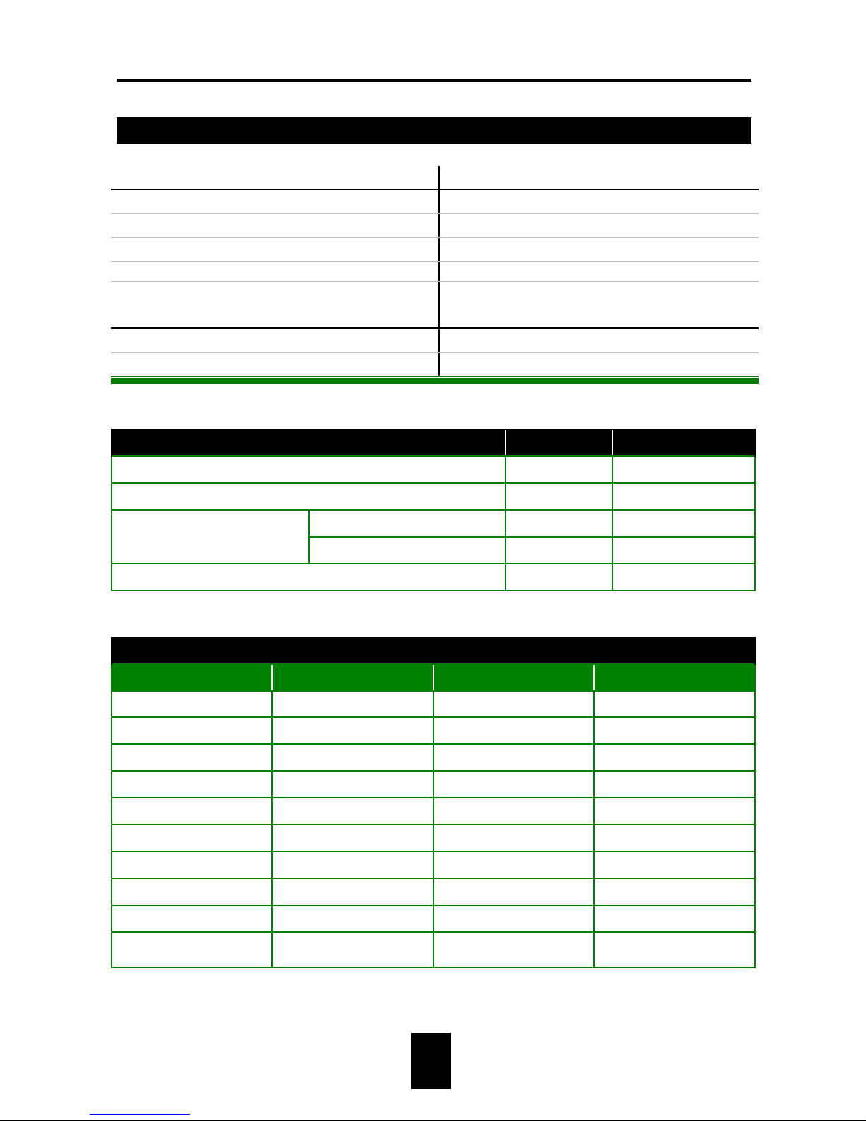
Fancom 747 APPENDIX 2: Installation report
2-1
APPENDIX 2: Installation report
User Installer
Name: Name:
Address: Address:
Place: Place:
% %
Installation Data
Date: Computer model: 747
Program version:
GENERAL SETTINGS Factory Own
Way of measurement ON-OFF
Time clock 0:00-24:00
Lower limit (%) 30
Acceptation limits
Upper limit (%) 30
Uniformity 10
CURVE SETTINGS
Bending point Day Lower% Upper%
1
2
3
4
5
6
7
8
9
10
Page 49
Fancom 747 APPENDIX 2: Installation report
2-2
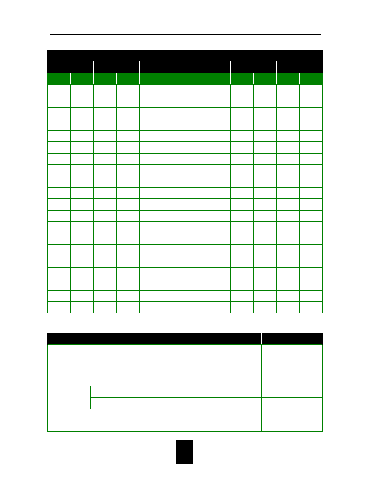
GROWTH STANDARDS
1 2 3 4 5 6
Day Wght. Day Wght. Day Wght. Day Wght. Day Wght. Day Wght.
SYSTEM SETTINGS Factory Own
Nr. of scales (max. 8) 1
Use
(1=broilers,2=turkeys,3=rearers,4=parent
stock)
1
Number stable 4
Accuracy:
Difference stable 1
Computer number 0
Baud rate 2400Bd
 Loading...