


CAUTION
READ INSTRUCTIONS CAREFULLY FOR SAFE
INSTALLATION AND FAN OPERATION.
FANAWAY EVO1 LED
CEILING FAN WITH DIMMABLE AND COLOUR
SHIFTING LED LIGHT
INSTALLATION
OPERATION
MAINTENANCE
WARRANTY INFORMATION
V2.0 – EN – AU EVO1 CS (07/2018)
Fanaway LED EVO1 Installation Instructions
IN AUSTRALIA
WARNING:
FOR SAFE USE OF THIS FAN AN ALL-POLE DISCONNECTION
MUST BE INCORPORATED INTO THE FIXED WIRING IN
ACCORDANCE WITH THE WIRING RULES.
As outline in clause 7.12.2 of AS/NZS 60335-1 for meeting the
minimum electrical safety of this standard.
Please note warranty will be void if installation is without a means
for an all-pole disconnection incorporated in the fixed wiring in
accordance with the wiring rules.
THANK YOU FOR PURCHASING
Thankyou for purchasing this quality Fanaway product. To ensure correct function and safety, please read
all instructions before using the product and keep the instructions for future reference.
SAFETY PRECAUTIONS
1. In Europe: This appliance can be used by children aged from 8 years and above and persons with
reduced physical, sensory or mental capabilities or lack of experience and knowledge if they have
been given supervision or instruction concerning the use of the appliance in a safe way and
understand the hazards involved. Cleaning and maintenance shall not be undertaken by children
without supervision.
2. In Australia: The appliance is not intended for use by persons (including children) with reduced
physical, sensory or mental capabilities, or lack of experience and knowledge, unless they have been
given supervision or instruction concerning the use of the appliance by a person responsible for their
safety.
3. Children should be supervised to ensure that they do not play with the appliance.
4. An all-pole disconnection switch must be incorporated into the fixed wiring, in accordance with local
wiring rules.
2 | P a g e

Fanaway LED EVO1 Installation Instructions
Example: If a fan is connected to a circuit that can be isolated via an
all-pole safety switch at the switchboard, then this is considered to
be an all-pole disconnection to the ceiling fan electrical circuit,
meeting the requirements of clause 7.12.2 of AS/NZS 60335.1.
A single-pole switch on the active of the receiver input of remote
control must also be included in the wiring, and located the
same room as the ceiling fan.
5. Do not dispose of electrical appliances as unsorted municipal waste, use separate collection
facilities. Contact your local government for information regarding the collection systems available. If
electrical appliances are disposed of in landfills or dumps, hazardous substances can leak into the
ground water and get into the food chain, damaging your health and well-being.
6. The structure to which the fan is to be mounted must be capable of supporting a weight of 45kg.
7. The fan should be mounted so that the blades are at least 2.3m above the floor in Europe or 2.1m
above the floor in Australia.
8. This fan is designed for indoor use only. Mounting the fan in a location where it is subject to water or
moisture is dangerous and will void the warranty.
9. Only a licensed electrician should execute the installation.
3 | P a g e

Fanaway LED EVO1 Installation Instructions
Fig. 1
BEFORE INSTALLATION
Unpack the fan and carefully identify the parts. Please refer to Fig 1.
4 | P a g e

Fanaway LED EVO1 Installation Instructions
1
Mounting bracket x 1
9
Blades x 4
2
Canopy screw x 4
10
Retraction mechanism x 1
3
Canopy x 1
11
Lamp base x 1
4
Down rod x 1
12
LED board x 1
5
Bolt x 1
13
Lamp shade x 1
6
Bolt & pin cover x 1
14
Wood screw x 2
7
Pin x 1
15
Remote x 1 set
8
Top housing x 1
16
LED driver x 1
Fig. 2
Fig. 3
INSTALLING THE MOUNTING BRACKET
The ceiling fan must be installed in a location so that the blades are a minimum 300mm spacing from
the tip of the blade to the nearest objects or walls.
Secure the hanging bracket to the ceiling joist or structure that is capable of carrying a load of at least
45kg, with the two long screws provided. Ensure at least 30mm of the screw is threaded into the
support.
NOTE: The bracket screws provided are for use with wooden structures only. For structures
other than wood, the appropriate screw type MUST be used.
Angled Ceiling Installation
This fan hanging system supports a maximum 18 degree angled
ceiling installation.
5 | P a g e

Fanaway LED EVO1 Installation Instructions
Fig. 5
Fig. 4
INSTALLING THE FAN
1. Installing the down rod
1) Feed the down rod (5) through the canopy (4) and the bolt and pin cover (6).
2) Remove the ball joint by loosening the set screw (3), insert the motor wires through the down rod then
secure the ball joint back to the down rod.
3) Insert the down rod to the coupling (7), line up the coupling holes with the down rod holes and insert the
bolt (8). Then insert the pin (9) to the end of the bolt.
4) Finally secure the down rod and coupling by tightening the two set screws (10) on the coupling. Fig. 4
2. Carefully lift the fan and place the down rod ball assembly into the spacing allocated in the mounting bracket
and lock the ball into place. Insert the LED driver into the lower layer of the mounting bracket then insert the
remote receiver into the top layer of the mounting bracket. Fig.4
3. Refer to the wiring diagram provided for Electrical Connection/installation. Fig. 5
WARNING: To prevent electrical shock or risk of fire, do not attempt to perform the electrical connection
wiring yourself. All electrical connections must be carried out by a licensed electrician.
NOTE: An additional all pole disconnection switch must be included in the fixed wiring.
6 | P a g e

Fanaway LED EVO1 Installation Instructions
Fig. 6
Fig. 7
4. After completing the electrical wiring at the mounting bracket terminal and connecting the remote receiver
power input wires and fixed wiring via the 4-port quick connectors (1); connect the LED driver power input
wires and remote receiver power output wires via the 2-port quick connectors (3); connect the LED driver PWM
signal input wires and remote receiver PWM signal output wires via the 3-port quick connectors (2); connect
the remote receiver fan output and motor input wires via the 4-port quick connectors (4); also connect the LED
driver output wires and LED light wires via the quick connectors (5). Fig. 5
5. Cover the mounting bracket with the canopy. Ensure all electrical wirings are tucked inside the canopy and
that it is not damaged during this step then secure with screws.
LIGHT KIT INSTALLATION
1. Remove the lamp shade from the lamp base by turning it anti-clockwise.
2. Loosen the screw (1) from the base bracket (3). Align the two slot screws (2) with the keyhole slots of the lamp
base (4). Fig.6
3. Turn the lamp base counterclockwise until the slot screws are firmly at the end of the slots.
4. Secure screw 1 back to the base bracket. Tighten all three screws. Do not over-tighten.
5. Connect the upper plug (1) from the driver to the lower socket (1) in the LED board (2). Fig.7
6. Finally install the lamp shade to the lamp base by turning it clockwise (5 – Fig.6).
USING YOUR CEILING FAN
REMOTE CONTROL
Your ceiling fan is controlled via the remote control. There are 4 buttons (HI, MED, LOW, OFF) to control the fan
speed and one button to control light on/off and dimming function. Fig. 10
Before operating the remote, the following must be considered.
- 2 x AAA 1.5V (size) batteries are required to operate the remote control. Remove the battery cover from the
back of the remote and insert 2 x AAA batteries. Ensure the polarities are correct as shown in the battery
compartment. (Batteries not included).
7 | P a g e
Fanaway LED EVO1 Installation Instructions
Fig. 10
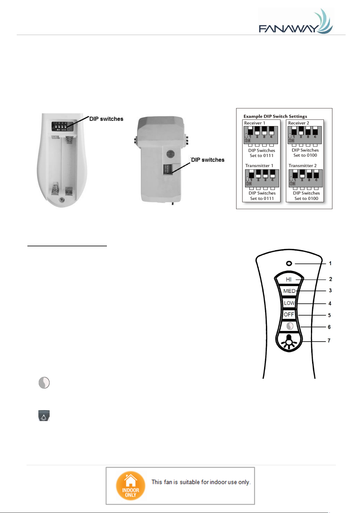
- The remote (transmitter) and receiver must be configured so that communication between each other is
paired up. This is achieved by setting the DIP switch on the receiver and remote on the same setting.
Note: The DIP switch assembly has 4 switches which can be setup to 16 different transmitting code
combinations. This is practical when there is more than 1 remote/receiver pair operating locally or in the
same room.
Note: To access the receiver DIP switches, remove the DIP switch cover.
Fig. 8 Remote battery compartment Fig. 9 Receiver DIP switch
OPERATING THE REMOTE:
Before you start using the remote, take the time to read through this section and
get familiar with the buttons and function of each button.
1. LED Indicator
The red LED indicator on the top of the transmitter will flash when the buttons are
active.
BUTTONS ON THE REMOTE
2. HI: Press this button to set the fan running at High speed.
3. MED: Press this button to set the fan running at Medium speed.
4. LOW: Press this button to set the fan running at Low speed.
5. OFF: Press this button to turn OFF the fan.
6. : Press this button to change the color temperature in the following order:
3000K → 5000K → 4000K → 3000K
7. : Press this button to turn ON/OFF the light and press and hold the button to access the light dimming
function.
The remote has memory function. If the fan or light is turned off by the isolating switch, it will memorise and
recover the last status when turned on next.
8 | P a g e

Fanaway LED EVO1 Installation Instructions
Fig. 11
REVERSE FUNCTION
Your ceiling fan can operate either in fan mode or reverse fan mode.
SUMMER Mode: The reverse switch should be in the “Left” (SUMMER) position to rotate the fan in an
anticlockwise direction. The airflow will be directed downwards, for cooling in summer.
WINTER Mode: The reverse switch should be in the “Right” (WINTER) position to rotate the fan in a
clockwise direction. The airflow will be directed upwards assisting in the circulation of warm air, for energy
conservation in winter.
The reverse switch is located in the top of the motor housing. Slide the switch to the LEFT for summer
weather operation. Slide the switch to the RIGHT for winter weather operation.
AFTER INSTALLATION
WOBBLE:
NOTE: ceiling fans tend to move during operation due to the fact that they are mounted on a rubber
grommet. If the fan was mounted rigidly to the ceiling it would cause excessive vibration. Movement of a
few centimetres is quite acceptable and DOES NOT suggest any problem.
TO REDUCE THE FAN WOBBLE:
Please check that all screws which fix the mounting bracket and down rod are secure.
NOTE: This fan has been precision balanced at the factory and will not need to be balanced again.
NOISE:
When it is quiet (especially at night) you may hear occasional small noises. Slight power fluctuations and
frequency signals superimposed in the electricity for off-peak hot water control, may cause a change in
fan motor noise. This is normal. Please allow a 24-hour “breaking-in” period, most noises associated with
9 | P a g e
Fanaway LED EVO1 Installation Instructions
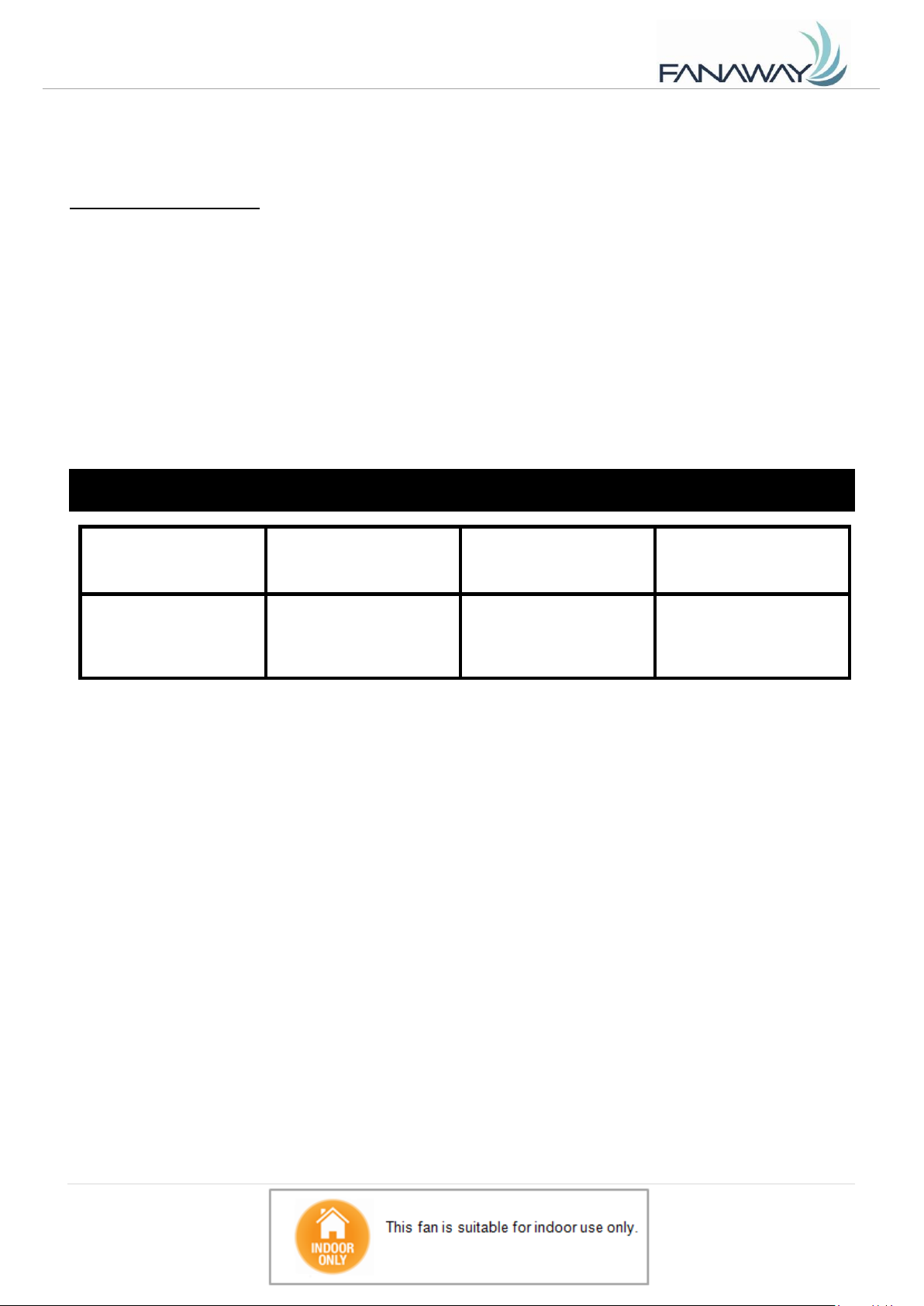
FAN models
Rated Voltage
Rated power (motor)
Rated power for light
48” FANS
220-240VAC
60W
40W,
3000K/5000K/4000K
LED driver model:
KLC-038-A2M
TECHNICAL INFORMATION
a new fan disappear during this time. Please note that this is not a product fault and as such is not covered
under warranty – All electric motors are audible to some extent.
CARE AND CLEANING:
Periodic cleaning of your ceiling fan is the only maintenance required. Use a soft brush or lint free
cloth to avoid scratching the paint finish. Please turn power off when you do so.
Do not immerse your ceiling fan in the water. It could damage the motor or the blades and create the
possibility of an electrical shock.
Ensure that the fitting does not come in contact with any organic solvents or cleaners.
To clean the fan blade, wipe with only a damp clean cloth with NO organic solvents or cleaners.
The motor has a permanently lubricated ball bearing so there is no need to oil.
NOTE: Always turn off the power at the mains switch before attempting to clean your fan.
10 | P a g e

Fanaway LED EVO1 Installation Instructions
Warranty
THIS WARRANTY IS VALID IN AUSTRALIA ONLY
Note:
Please complete the following details when you have unpacked the product and retain this card with the purchase
invoice or sales docket.
Warranty
These products are covered by a Warranty in addition to all rights available to you by statute. The Warranty is for a
period of twenty four (24) months from the date of purchase, subject to the following conditions. Fanaway undertakes,
at its option, to repair or replace, free of charge, each product or part thereof subject to the following conditions. The
conditions abovementioned are:
1. That the purchaser carefully follows all instructions provided and complies with electrical wiring regulations;
2. That the purchaser carefully follows the installation instructions provided in the owner’s handbook relating to
the proper use and care of the product and does not use the product for any purpose other than the domestic
use for which it has been designed;
3. That the product was purchased and is installed in Australia;
4. That this Warranty does not extend to:
A. Optional light diffusers
B. Light globes
C. Damage to plastic light dome caused by inappropriate cleaning
D. Damage to surface coatings caused by cleaning or maintenance using inappropriate cleaning products
E. Defects caused by normal wear and tear, accident, negligence, alteration or misuse;
F. A product dismantled, repaired or serviced by any serviceman other than an authorized employee or agent
of Fanaway
G. Product installed by an unqualified person. Must be a qualified electrician in Australia
H. Damage or defects caused by fans being installed externally.
(FANS ARE DESIGNED FOR INDOOR USE ONLY).
5. The provisions of this warranty do NOT apply to other Ceiling Fans.
6. The provision of service under this Warranty is limited by the boundary of the nearest service agent’s area.
Traveling cost incurred for the service outside this area is not covered by this warranty and will incur commercial
cost to be paid by the customer regulated by the number of kilometers traveled beyond the service area.
7. The cost associated with the hire of extension ladders and scaffolding to service fans installed on ceilings
greater than 3 meters will not be covered by this warranty. Such costs will be borne by the customer.
In the event of a service being required, please call the Lucci Warranty Service Hotline acting as the service agent
for Fanaway on 1800 602 243 between 9AM and 5PM (E.S.T) Monday to Friday. Ensure you have the following
details on hand. If you are unable to establish the date of purchase, or the fault is not covered by this Warranty, or
if the product is found to be in working order, you will be required to bear all service call charges.
11 | P a g e
Fanaway LED EVO1 Installation Instructions
PRODUCT TYPE: ......................................................
MODEL NUMBER: .....................................................
SERIAL NUMBER: .....................................................
DATE OF PURCHASE: ..............................................
INVOICES/SALES DOCKET NO: ..............................
PURCHASER’S NAME: .............................................
PURCHASER’S ADDRESS: ......................................
RETAILER’S/DEALER’S NAME: ...............................
RETAILER’S/DEALER’S ADDRESS: ........................
INSTALLED BY: …………………………………………
LICENCE NUMBER OF INSTALLER: …………………
PHONE NUBER OF INSTALLER: ……………………..
DESCRIPTION OF FAULT: …………………………….
Our goods come with guarantees that cannot be excluded under the Australian Consumer Law. You are entitled
to a replacement or refund for a major failure and compensation for any other reasonably foreseeable loss or
damage. You are also entitled to have the goods repaired or replaced if the goods fail to be of acceptable quality
and the failure does not amount to a major failure.
CONTACTS:
Contact Lucci Warranty Service Hotline acting as the service agent for Fanaway on 1800 602 243 between 9AM
and 5PM (E.S.T) Monday to Friday, or go to Website: www.fanaway.com for more information.
Distributed by:
Beacon Lighting
140 Fulton Drive
Derrimut, Victoria, 3030
Australia
Ph +613 9368 1000
Fax +613 9360 9332
Email: warranty@beaconlighting.com.au
12 | P a g e
 Loading...