

Page 1
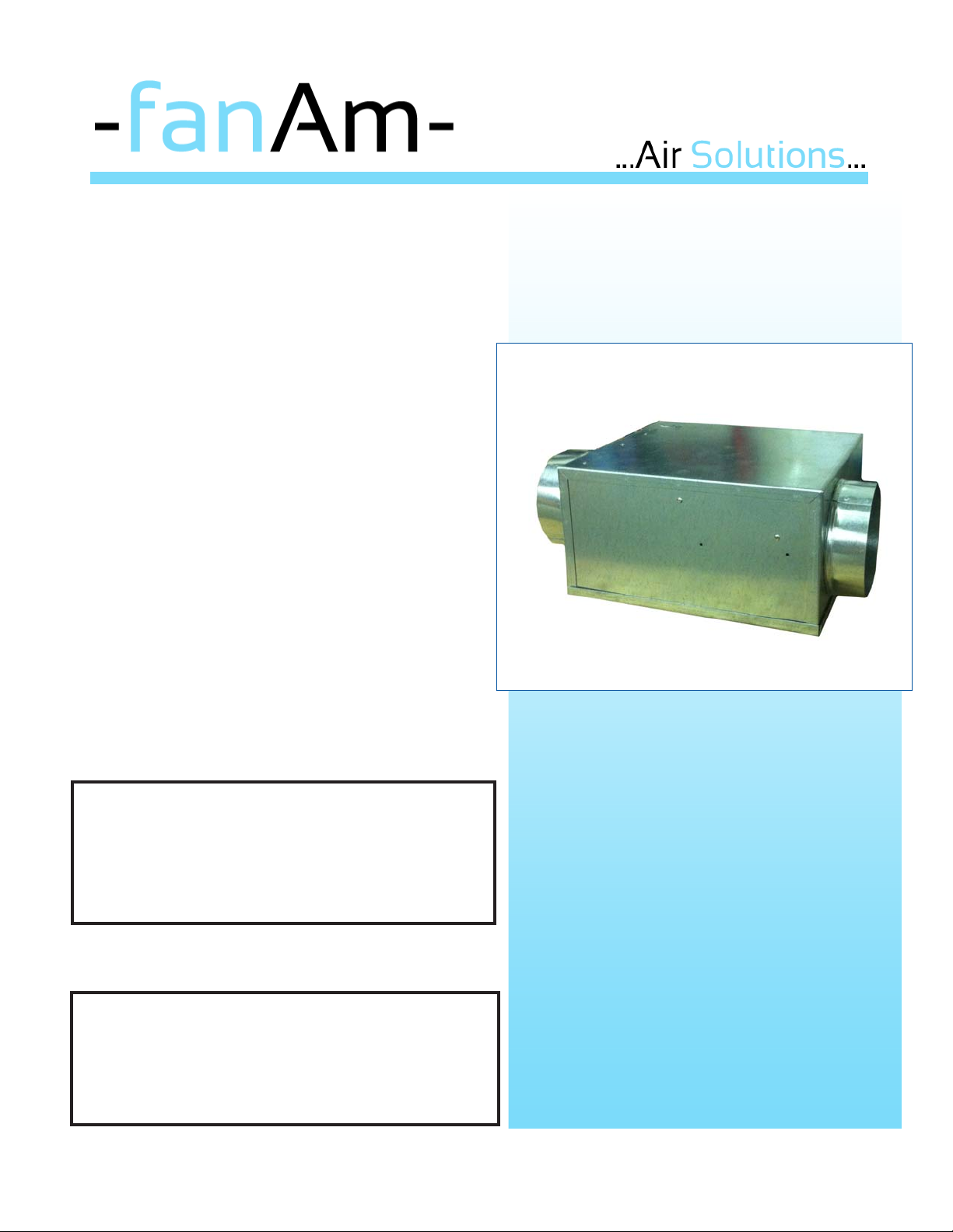
DQC Series Inline Fans
INSTALLATION, OPERATION, AND MAINTENANCE MANUAL
This publication contains the installation, operation
and maintenance procedures for standard units of
the DQC Series Fans
Carefully read this publication prior to installation.
Receiving and Inspection
Carefully inspect the fan and accessories for any
damage and shortage immediately upon receipt of the
fan.
• Turn the wheel by hand to ensure it turns freely and
does not bind.
• Inspect dampers (if included) for free operation of all
moving parts.
• Remove shipping tape.
• Record on the Delivery Receipt any visible sign of
damage.
Handling
Lift fan by the outside housing (box) or by the blower
mounting brace.
Storage
If the fan is stored for any length of time prior to
installation, store it in its original shipping crate and
protect it from dust, debris and weather.
Low Profile DQC-Series
Removable Bottom Access
WARNING
This unit has rotating parts. Safety precautions
should be exercised at all times during installation,
operation, and maintenance.
ALWAYS disconnect power prior to working on fan.
PERSONAL SAFETY
Disconnect switches are recommended. Place the
disconnect switch near the fan in order that the
power can be swiftly cut off in case of an emergency,
and in order that maintenance personnel are provided
complete control of the power
Page 2
Installation
Motor Installation
All DQC units are shipped with motors mounted at
the factory.
Fan Installation
1. DQC Series fans are compact, versatile and may
be mounted in any position. The recommended
mounting location of the fan is a minimum of 15
linear feet from the dryer exhaust port in order to
avoid moist or wet lint to gather in the fan. If a
lint trap is being used between the fan and the
dryer, the fan can be mounted closer than the
recommended 15 feet. The DQC fan warranty is
increased from three(3) to five(5) years if F anAm’s
2100 Series lint trap is used in conjuction with the
fan.
2. Because this unit has rotating parts, safety
precautions should be excercised during
installation, operation and maintenance procedures.
3. WARNING! Unless specifically built for hazardous
environments, do not use the fans where the electrical system could ignite combustible or flammable
material.
4. Remove unit from package and inspect within 15
days after receipt. If damaged, report damage to
carrier . Do NO T operate this unit with visible damage
to the blower or impeller assembly . Turn centrifugal
impeller by hand to assure free rotation.
5. CAUTION: Before proceeding with installation, make
sure there is no electrical connection. All wiring should
be in accordance with local ordinances and the
National Electric Code.
WARNING: Check voltage to the fan to assure it
corresponds with the motor name plate.
6. CAUTION: Always vent this unit to the outside,
NOT into spaces within ceilings or walls, attics, crawl
spaces, garages, etc.
7. Keep drywall spray, construction dust, etc., off
and out of the impeller assembly to avoid motor bearing damage, noise, or unbalanced impellers.
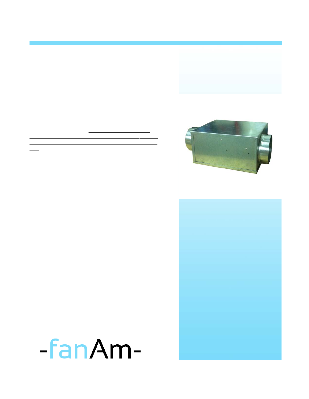
DQC
Page 3

Detailed Installation Instructions
P
120 VA C
All dimensions in inches
12
1. Provide a solid frame against which the unit will
be mounted (see dimensional data for proper frame
sizing). Make sure that the housing will be flush with
the finished ceiling, once the unit has been fixed into
the frame.
2. Bend mounting bracket and fasten it in desired
location in the ceiling.
3. Mount brackets with self-drilling tap screws in
desired position on the unit housing. Fan mounting
brackets are adjustable vertically on the fan housing.
4. Hang unit. Tighten mounting screws as firmly as possible to assure secure support and lowest possible
sound levels. Note: A secure solid frame will also help
sound levels to remain at a minimal.
11
5
Inlet
Wiring Diagrams
Using Current Sensor
Outlet
6.5
NEUTRAL/WHITE
4 7/8
5. Wire unit.
Turn power off at circuit breaker or fuse panel
a) Remove desired knockout and open fan
terminal box from inside the fan.
Connect incoming electric supply per wiring
diagram.
b) Use appropriate electrical connector and strain
relief to secure the incoming electric cable.
6. Connect ductwork to the collars 4 and 5 inch.
Tape joints with duct tape.
7.Reattach lid with screws.
COMPAX FAN
OWER TO DRYER
DRYER JUNCTION BOX
Hot (Black lead)
L1
120 VAC
Supply Voltage
Neutral (White lead)
Neutral (white lead) from dryer
N1
L2
N2
CURRENT
SENSOR
WITH TIMER
Hot (Gray lead)
Supply
Voltage
For Fan
Neutral (White lead)
Page 4

Wiring Diagrams cont.
SPECIAL WIRING PRECAUTIONS
All installations should be wired according to the following diagrams.
Failure to comply will cause the motor to “hum” or not work.
1. Turn off power at service entrance before wiring this fan.
2. Read the fan serial number to determine the current draw. Check
that available supply is suitable.
3. Be certain to use proper connector type for securing conduit cable.
4. Connect electrical supply per diagrams supplied here.
Troubleshooting
1. If fan fails to operate, please check the following:
a) Fan has power.
b) Consult wiring diagrams included to assure proper connection.
c) To assure proper contact, check motor lead wiring, incoming supply wiring and capacitor connections.
d) If possible, use a meter to test for continuity between fan leads. Please note that capacitor will show no
reading if tested with meter.
2. If fan still fails to operate, consult FanAm Distributor for return/replacement instructions.
Maintenance
1. Since fan bearings are sealed and have been provided with an internal lubricating material, no lubrication is
necessary.
2. At least once a year, clean any particles accumulated in the fan.
CAUTION: Never attempt to open the fan without the electrical service to the fan locked in the “OFF” position.
Limitation of W arranty and Liability
This warranty does not apply to any FanAm product or part which has failed as a result of faulty installation or abuse, incorrect electrical connections or alterations made by others, or use under abnormal
operating conditions or misapplication of the products or parts. We will not approve for payment any repairs not made by us or our authorized agent without prior written consent. The foregoing shall constitute
our sole and exclusive warranty and our sole and exclusive liability, and is in lieu of all other warranties, whether written, oral, implied or statutory . There are no warranties which extend beyond the description
on the page hereof. We do not warranty that said goods and articles are of merchantable quality nor that they are fit for a particular purpose. Our liability on any claim of any kind, including negligence, for any
loss or damage arising from or connected with, or resulting from, the sale and purchase of the products and parts covered by this proposal, acknowledgement, order or from the performance or breach of any
contract pertaining to such sale of purchase, or from the design, manufacture, sale, delivery, resale, inst allation, technical direction in installation, inspection, repair , operation or use of any product or part
covered by the proposal, acknowledgement, order or furnished by FanAm shall, in no case, exceed the price allocable to the products or parts thereof which give rise to the claim and shall terminate at the end
of the applicable warranty period of said product or part. In no event whether as a result of breach of contract, or warranty or alleged negligence, defect, incorrect advice or other causes, shall FanAm be liable
for special or consequential damages, including but not limited to loss of profits or revenue, loss of use of equipment or any associated equipment, cost of capital, cost of substitute equipment, facilities or
services, downtime cost, or claims of customers of purchases for such damages. FanAm neither assumes nor authorizes any person to assume for it any other liability in connection with the sale of its products
or parts. Some jurisdiction do not allow the exclusion or limitation of incidental or consequential damages, so the above limitations and exclusions may not apply to you.
EXTENDED WARRANTY
FanAm warrants its COMP AX Series fan and parts to be free from defects in workmanship and service for period of one (3) years from the date of purchase. If the unit is furnished with FanAm’ s lint trap,
the warranty is extended to (5) years from the date of purchase. Products and parts not specifically designed for use in a corrosive or explosive environment shall have no warranty and the user assumes
full liability for use in such environments. Our obligation under this warranty is limited to the repair or replacement as our option, without cost at our facility, of any p art or parts thereof which shall, within the
warranty period, be returned to us with transportation charges prepaid, and which our examination discloses as being defective. All requests for repair or replacement must be directed to FanAm for
authorization prior to the return of any product or part. This warranty gives you specific legal rights and you may also have other rights in the jurisdiction in which you reside. (It is incumbent upon the claiment
to provide substantiation of purchase of installation dates if such question should arise.)
DISCLAIMER
FanAm Inc. has made a diligent effort to illustrate and describe the products in this literature accurately however, such illustrations and descriptions are for the sole purpose of identification, and do not
express or imply a warranty that the products are merchantable, or fit for a particular purpose, or that the products will necessarily conform to the illustrations.
 Loading...