

Page 1

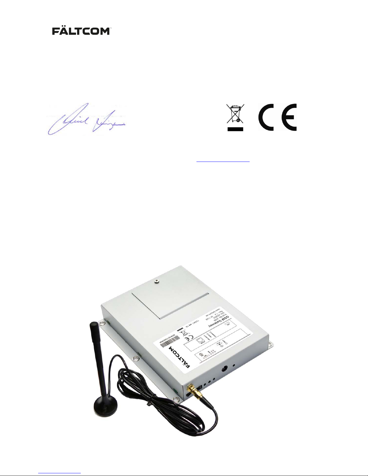
GSM Gateway 252236
User Manual
Art. No. 162236M V3.21D 2016-02-18
Page 2

162236M User Manual GSM Gateway Page 2 of 20
Table of contents
1. Installation .............................................................................................................................. 5
1.1 PIN code ........................................................................................................................ 5
1.1.1 PIN code deactivated ...................................................................................... 5
1.1.2 PIN code activated .......................................................................................... 5
1.2 Startup 5
1.3 Turn off the GSM Gateway ............................................................................................ 5
1.4 Change SIM card ........................................................................................................... 5
2. Front panel connectors and indications .............................................................................. 6
3. Back panel connectors and indications .............................................................................. 7
4. Battery ..................................................................................................................................... 8
4.1 Low battery voltage indication ........................................................................................ 8
4.2 Battery fault alarm .......................................................................................................... 8
5. SMS functionality ................................................................................................................... 9
5.1 Low battery voltage indication ........................................................................................ 9
5.2 Dial tone battery alarm - Dial tone 2 ............................................................................ 11
5.3 Status 12
5.4 Reset 13
5.5 Ask for the current Gain ............................................................................................... 13
5.6 Change the Gain .......................................................................................................... 13
6. Upgrade Tool ........................................................................................................................ 15
6.1 Firmware upgrade ........................................................................................................ 16
6.2 Setup 16
6.2.1 LED control on signal strength ................................................................... 17
6.2.2 Battery control ............................................................................................... 17
6.2.3 Battery SMS ................................................................................................... 17
6.2.4 GSM SMS Access code ................................................................................ 18
6.2.5 Gain control ................................................................................................... 18
6.2.6 POTS1 power saving .................................................................................... 18
6.2.7 Tone generation ............................................................................................ 18
6.2.8 Battery failure signal – Dial tone battery alarm.......................................... 18
7. Technical Data ...................................................................................................................... 19
8. Repair return procedure ...................................................................................................... 20
9. Contact Information ............................................................................................................. 20
Page 3
162236M User Manual GSM Gateway Page 3 of 20
Declaration of Conformity
We, Fält Communications AB, Vasagatan 23, SE-903 29 Umeå, Sweden. Hereby declare that this product,
Fältcom GSM Gateway 202236, conforms with the following directives: R&TTE 1999/5/EC, EMC 2004/108/EC,
LVD 2006/95/EC, RoHS 2002/95/EG and WEEE 2002/96/EG. The product complies with the following
standards/norms: EN 55022(2006) and A1(2007), EN 55024(1998) and A1(2001) and A2(2003), EN
60950(2006) and ETSI EN-301 511
Umeå, Sweden, January 2013
Mikael Långström, CEO
Fält Communications AB
The declaration of conformity can be consulted at www.faltcom.com
Content of delivery
- GSM Gateway, art no. 202236
- Antenna SMA, mag n et foot, art no. 112322
- GSM Gateway Manual (this document), art no. 162236M
- Power adapter 230VAC/12 VDC, art no. 132010
- Modular cable, art no. 122033
- Terminal connector
Page 4
162236M User Manual GSM Gateway Page 4 of 20
CONNECTIONS
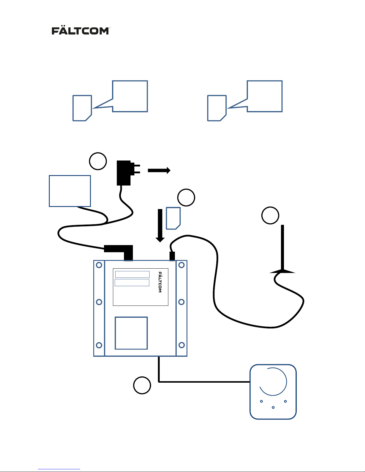
Insert the SIM card, connect the Antenna, the lift phone Fältcom ECII Flex and Power
SIM
Lift phone Fältcom ECII Flex
in LIFT CAR
TELE
PHONE
ANT
Power
Supply
12-24 VDC
230 VAC
OR
Battery
ANTENNA
SIM PIN code
Activated or deactivated PIN code
OR
ACTIVATED
Set PIN
code to:
1234
SIM
DEACTIVATED
Turn of
PIN code
lock
SIM
1
2
3
4
…
GSM Gateway
Page 5

162236M User Manual GSM Gateway Page 5 of 20
1. Installation
Find a suitable place where to mount the GSM gateway following these guide lines:
• Make sure the GSM coverage is good before the GSM gateway is m ounted.
Place the Gateway near a window if possible.
• Make sure the LEDs on both sides are visible.
• Make sure there is a power source, 230 VAC or 12-24 VDC reachable.
• Connect the antenna. Place the antenna as far away from the Gateway as possible.
The antenna can be placed on any magnetic metal surface.
• Connect the Fältcom ECII Flex to the Phone input.
Use the 122033 Modular cable and the terminal connector if required.
1.1 PIN code
Note: The GSM gateway must always be turned off before inserting or removing the SIM card. Please
see section “Turn off the GSM Gateway” before removing a SIM card.
Choose whether the PIN code should be activated or deactivated.
1.1.1 PIN code deactivated
Use a mobile phone or other equipment to deactivate the PIN code on the SIM card.
1.1.2 PIN code activated
The PIN code must be set to “1234”. Use a mobile phone or other equipment to set the PIN code to
“1234”.
At startup the GSM Gateway will aut om at ically change the PIN code to a random 4-digit code to
prevent misusage of the SIM card. If the SIM card is to be used later; use the PUK code to unlock the
SIM.
1.2 Startup
Start the GSM Gateway:
• Gently insert the SIM-card into the GSM unit as shown in the pictures above.
Make sure the cut corner of the SIM is on the left side and the connect or pads facing down.
• Connect the power cable.
The startup might take up t o 30 seconds before the GSM Gateway has established a
connection with the GSM network. For information on how to understand the LED indications,
please see section 2 and section 3 below.
1.3 Turn off th e GSM Gateway
1. Remove the DC power connector from the GSM Gateway.
2. Push the RESET button with a short push to turn the unit off.
1.4 Change S I M card
If the SIM-c ar d needs to be changed; the new SIM-card must have “1234” as PIN-codes or have the
PIN-code deactivated.
1. Turn off the GSM Gateway; remove the DC power connector from the GSM Gateway.
2. Push the RESET button with a short push to turn the unit off.
3. Remove the old SIM and insert the new SIM as shown in the pictures above.
4. Connect the power cable.
Page 6
162236M User Manual GSM Gateway Page 6 of 20
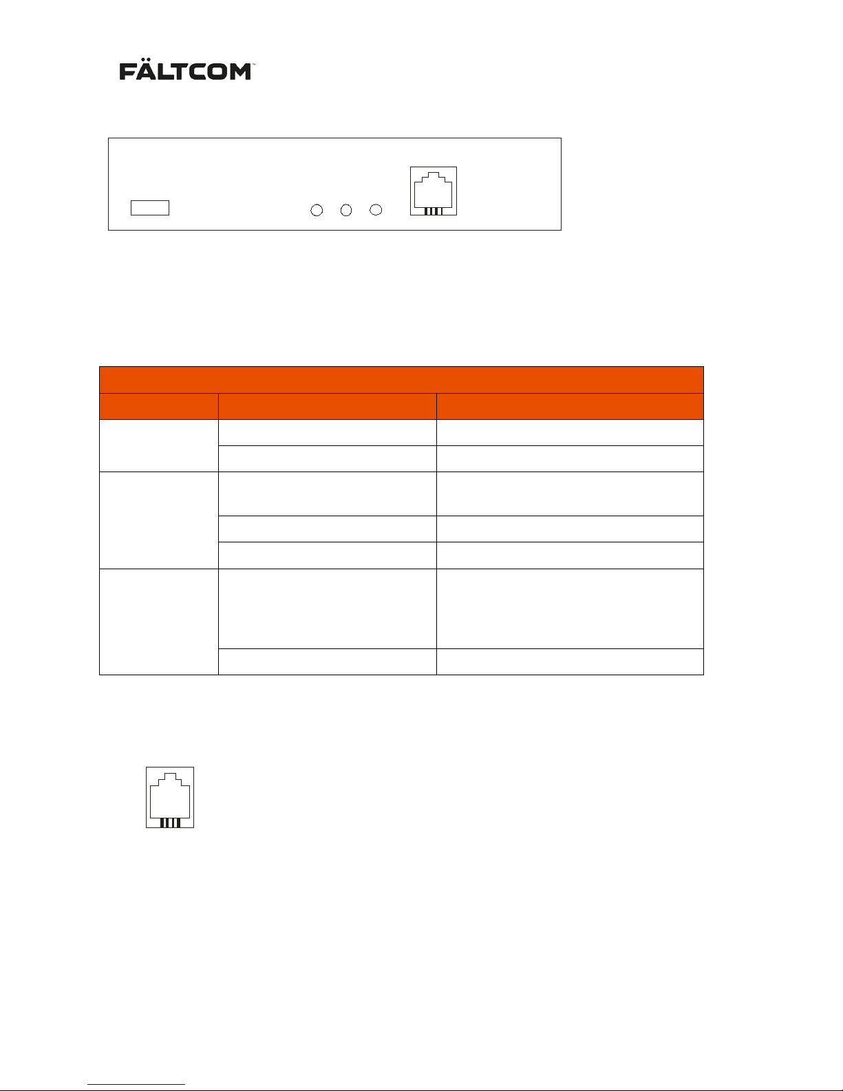
2. Front panel connectors and indications
USB
PHONE
PWR/STAT
BATT
PHONE 1
USB USB 2.0 Mini connector to be used for connection with a PC. The USB can be
used for updating the software of the GSM Gateway and also for adjusting
parameters, such as battery tripping limits. For more information please see
section 5.3 “
LED Indicators
LED
Status
Indicates
PWR/STAT
1000 ms ON / 1000 ms OFF
Normal status
100 ms ON / 1500 ms OFF
Backup power in use
PHONE
(Red LED)
OFF
Phone device is On-hook (Normal
status)
Flashing
Ringing signal on line
ON
Phone device is Off-hook
BATT
(Red LED)
Flashing
Battery problem. The battery is not
connected or the battery has not
passed a battery test. See also
section 4 nedan.
OFF
Battery state is normal
PHONE Connection to standard telephone device
PHONE 1
1
No
PHONE (RJ11)
1 2
La
3
Lb
4
Page 7
162236M User Manual GSM Gateway Page 7 of 20
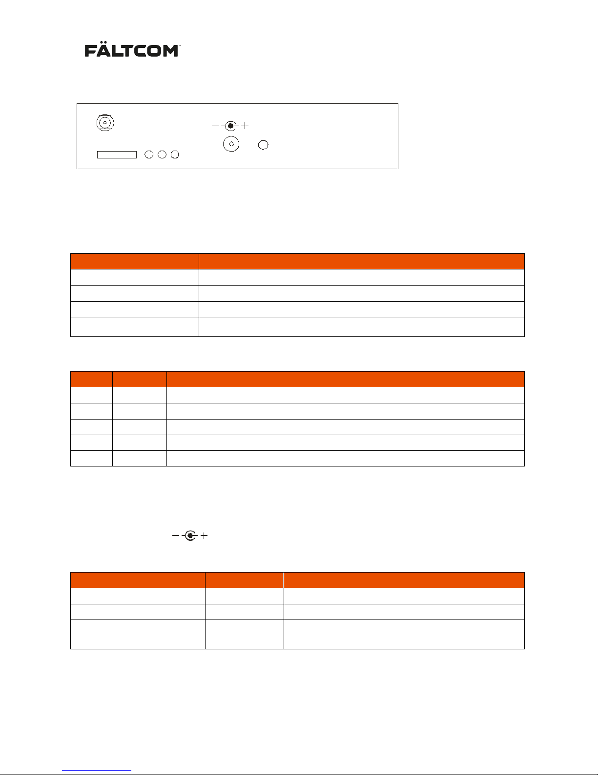
3. Back panel connectors and indications
RESET
SIM
ANT
S2
GSM
S1
12V DC
ANT SMA Connector for the antenna
SIM Input of the SIM card
GSM Status for the GSM connection when the GSM Gateway is up
and running (Green LED):
GSM
Indicates
OFF
Faulty GSM unit
800 ms ON / 800 ms OFF
No service, No connection with GSM network or SIM-card missing.
100 ms ON / 1500 s OFF
Connection with the GSM network OK, Backup power in use
ON
Normal status. Connection with the GSM network OK, AC-powered.
S1 and S2 Indications for GSM signal strength (Green LED):
S1
S2
Signal strength
OFF
OFF
Bad
ON
OFF
Good ( default 15 = -83 dBm)
ON
ON
Very good ( default 25 = -63 dBm)
Flash
OFF
Good, Backup power in use.
Flash
Flash
Very good, Backup power in use.
LED levels are programmable in 2 dB steps from -113 dBm to -51 dBm via USB ( Fältcom Manager)
12V DC
12V DC
No PWR
+ + 9-28 V DC
- GND
RESET
Type of RESET activation
Power supply
Result
Short push
External
Reboot of GSM Gateway
Short push
Battery
GSM Gateway is switched off
Hold button for >20 sec External
All settings are reset to factory settings. This is
indicated by the LED´s PHONE and BATT
Note: Factory reset also changes the PIN-code back to the default “1234” if PIN –code is in use, this
may cause the SIM-card to be locked if a SIM-card is mounted inside the GSM Gateway.
Page 8

162236M User Manual GSM Gateway Page 8 of 20
4. Battery
The battery is supervised in two different ways. The first “low battery voltage indication” is activated
when the battery voltage is too low for any reason. The second is a “battery fault alarm” activated
when the battery capacity is too low and it is time to replace the battery.
In case there is a battery alarm/low battery voltage indication, the GSM Gateway will chang e the dial
tone; see section Technical Data for information on Dial tone battery alarm specifications. The
emergency alarm will detect the new dial tone and send a battery alarm to the receiver . See section 5
SMS functionality or 6.2 Setup for information on how to turn the Dial tone battery alarm off.
4.1 Low battery voltage indication
A “low battery voltage indication” is activated if the battery voltage drops below 4.6 VDC when the unit
is powered by the battery.
The indication is sent by SMS. Please view SMS functionality for information on settings or how t o use
the USB connector and Fältcom Manager Software.
If the unit is powered by the batt er y and the battery voltage drops below 4.0 VDC the GSM Gateway
will shut off to prevent permanent damage of the battery. These voltage levels are not programmable.
4.2 Battery fault alarm
A “battery fault alarm” is shown by a red LED, see section 2 above, and by a change of the normal dial
tone, see section 5.2 below.
The first batter y test is made after 48 hours and the following every 24 hour. During a battery test a
load is connected to the battery and the battery voltage measured. A battery test lasts for 5
(1)
minutes
and if the voltage drops below 4.4
(2)
VDC during this time a “battery fault alarm” is activated.
A battery test will not be performed when the GSM Gateway is powered by the battery. An active
“battery fault alarm” is automatically reset after a passed battery test.
Normally the battery will last 2-4 years but this is very much depending on the surrounding
temperature and how much the battery is used. When the battery is failing, simply replace the battery
with an equivalent type - replacement batteries are available from Fältcom sales. Fältcom batteries are
designed with a wider temperature range and approved to be used with the product. Other types of
batteries might damage th e GSM Gat eway. If other supplier of batteries are used Fältcom cannot
guarantee functionality as the function may not be as good. Levels for battery alarm may also need to
be changed.
A polyswitch fuse is integrated in the battery package to prevent it from damage in case of high
temperatures. The fuse is automatically reset when the temperature is normal again.
(1) 5 minutes is the default setting. The time is programmable via USB (Fältcom Manager).
(2) 4.4 V is the default setting. The levels for the “battery fault alarm” is programmable via USB
(Fältcom Manager) or via SMS by the distributor.
Page 9
162236M User Manual GSM Gateway Page 9 of 20
5. SMS functionality
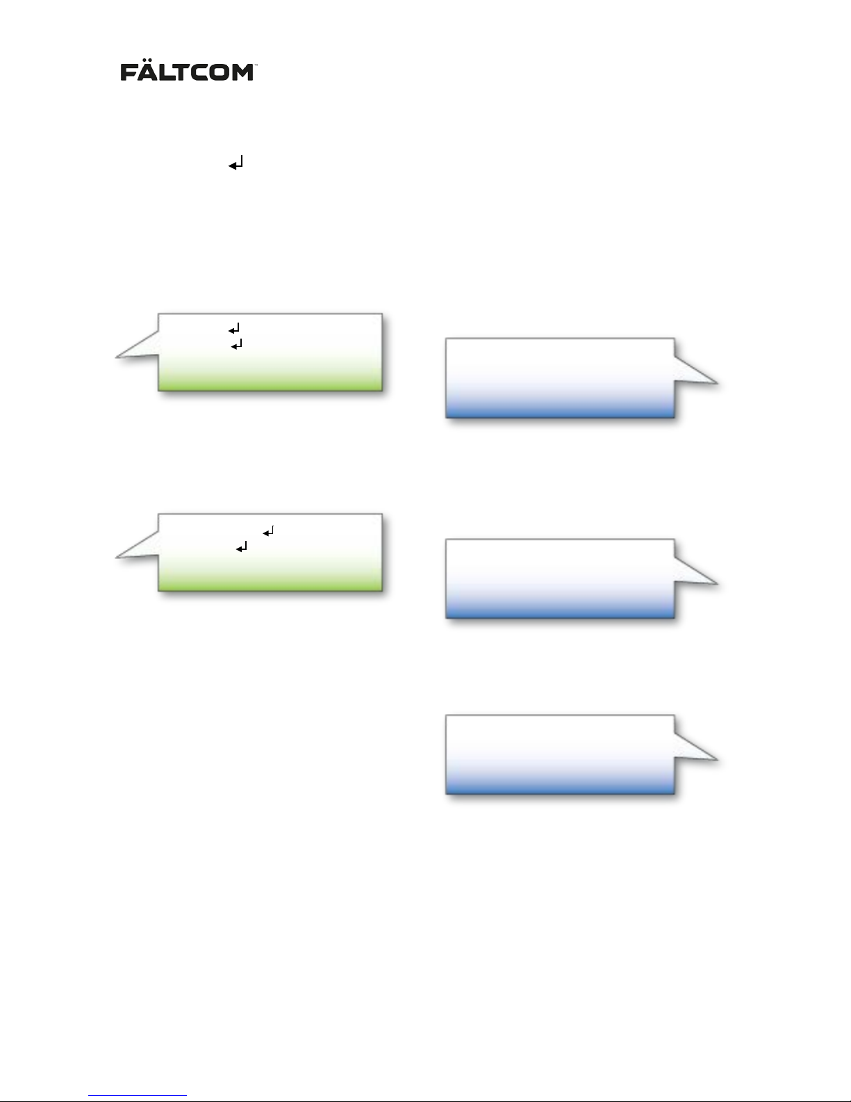
Note: The symbol means new line.
5.1 Low battery voltage indication
It is possible to generate an SMS when a Low battery voltage indication occurs; the functionality is
activated by sending an SMS to the GSM Gateway. The SMS m ust include the telephone number and
an alarm text. The SMS is not case sensitive. In the example below the batt ery alarm level is not
changed. The GSM will acknowledge a correct programming by returning a SMS.
In the example below the battery alarm level is changed to 4.0 V (4000 mV).
In this example a Low battery voltage indication will generate the following:
Balarm:On
070321213
Low battery voltage from Lift 452
SMS acknowledgement from GSM Gateway:
Balarm:On=4000
070321213
Low battery voltage from Lift 452
SMS to GSM Gateway:
Balarm:On=4000
070321213
Low battery voltage from Lift 452
SMS acknowledgement from GSM Gateway:
Low battery voltage from Lift 452
SMS from GSM Gateway:
Balarm:On
070321213
Low battery voltage from Lift 452
SMS to GSM Gateway:
Page 10
162236M User Manual GSM Gateway Page 10 of 20
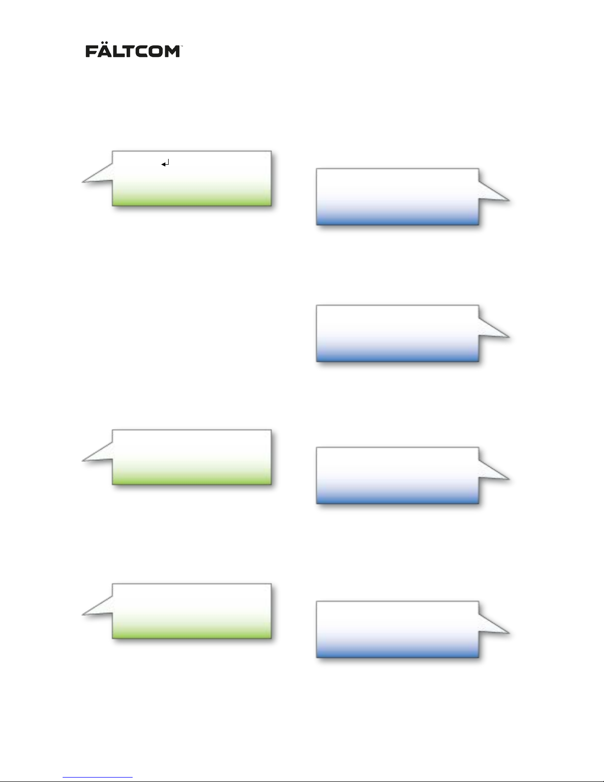
It is possible to generate an SMS (Bares) when the battery voltage gets above t he set voltag e level.
This function is activated by sending an SMS to the GSM Gateway. T he SMS must include and
appropriate text. The SMS is not case sensitive. Bares SMS is always sent to the same number as
Balarm.
In this example when the power to the Gateway is reestablished and the battery voltage is above the
set voltage level the following is sent from the GSM Gateway.
Both functions described above are switched off by sending the following to the GSM Gateway:
The Battery replaced SMS (Bares) function described above can be switched off separately by
sending the following to the GSM Gateway:
Balarm: ON
Bares: OFF
SMS acknowledgement from GSM Gateway:
Balarm: OFF
Bares: OFF
SMS acknowledgement from GSM Gateway:
Battery V level OK from Lift 452
SMS from GSM Gateway:
Bares:On
Battery V level OK from Lift 452
SMS acknowledgement from GSM Gateway:
Bares:On
Battery V level OK from Lift 452
SMS to GSM Gateway:
Balarm: off
SMS to GSM Gateway:
Bares:off
SMS to GSM Gateway:
Page 11
162236M User Manual GSM Gateway Page 11 of 20
5.2 Dial tone battery alarm - Dial tone 2
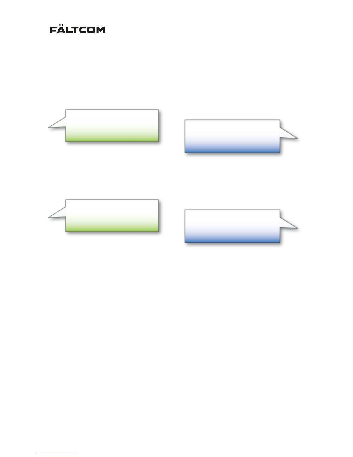
The Dial tone battery alarm to the lift phone, indicating a battery fault alarm, is default activated but
can be turned off. In case the function is deactivated the GSM Gateway will always use normal dial
tone when the line is taken off-hook.
To deactivate the Dial tone battery alarm (dial tone 2); send the SMS below to the GSM Gateway. The
GSM will acknowledge a correct programming by returning a SMS.
To reactivate the dial tone 2 (battery alarm/low battery voltage indication, dial tone) send the below
SMS to the GSM Gateway. The Gateway will return an acknowledgement.
Dial tone2:ON
SMS acknowledgement from GSM Gateway:
Dial tone2:OFF
SMS acknowledgement from GSM Gateway:
Dial tone2:off
SMS to GSM Gateway:
Dial tone2:on
SMS to GSM Gateway:
Page 12
162236M User Manual GSM Gateway Page 12 of 20
5.3 Status
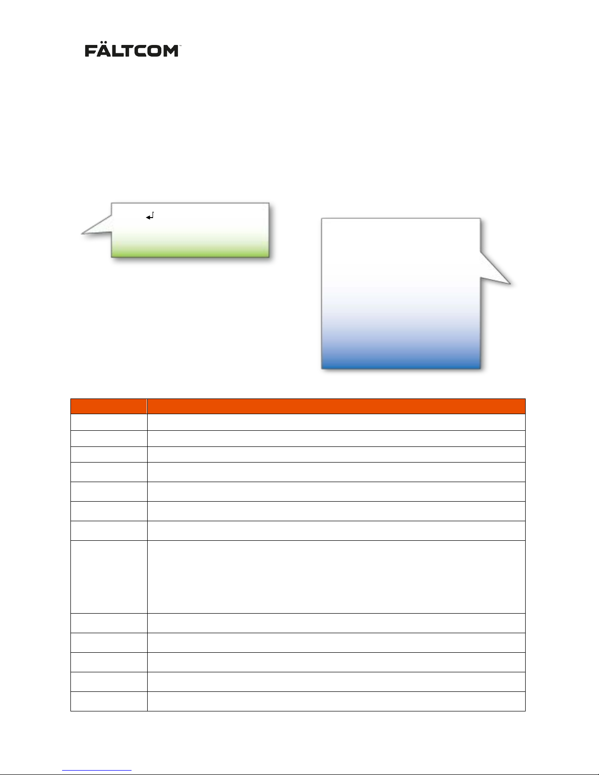
Get current status of the Gateway by sending a “Status” SMS. The SMS must contain the SMS
Access code followed by a new line and the word Status. The default Access code is 1111 and can be
changed using the Fältcom Manager SW.
If the access code or the request command (Status) is incorrect, the GSM Gateway will answer
“Request command not supported”. If the SMS is correct the Gateway will return an
acknowledgement.
Description table of the status SMS:
Parameter
Description
SN
Serial number of the Gateway
FW
Firmware version of the Gateway
S
Current signal strength (signal strength in dBm)
S H/L
Highest signal during last 24h/lowest signal during last 24h since last restart.
UT
Uptime counter, presented in days, hours and minutes.
LC
Last called number, not saved in case of restart.
PWR
Current power source – Mains or Battery
LRR
Last restart reason
xxx1 Power on
xx1x External reset
x1xx Watch-dog reset
1xxx Low voltage reset
Op
Current operator in use, in text format
CID
Cell ID of the base station
LAC
Location area code of network cell
Line
POTS line On-hook or Off-hook
LHoff
Time since last hook-off, presented in days, hours and minutes.
1111
Status
SMS to GSM Gateway:
SN:V12345
FW:3.19
S:31 (-51)
S H/L:2/31 (-109/-51)
UT:450d21d22m
LC:0701234567
PWR:Battery
LRR:Reset
Op:Vodafone
CID:25781258
LAC:65534
Line:On
LHoff:02d01h36m
SMS acknowledgement from GSM Gateway:
Page 13
162236M User Manual GSM Gateway Page 13 of 20
5.4 Reset
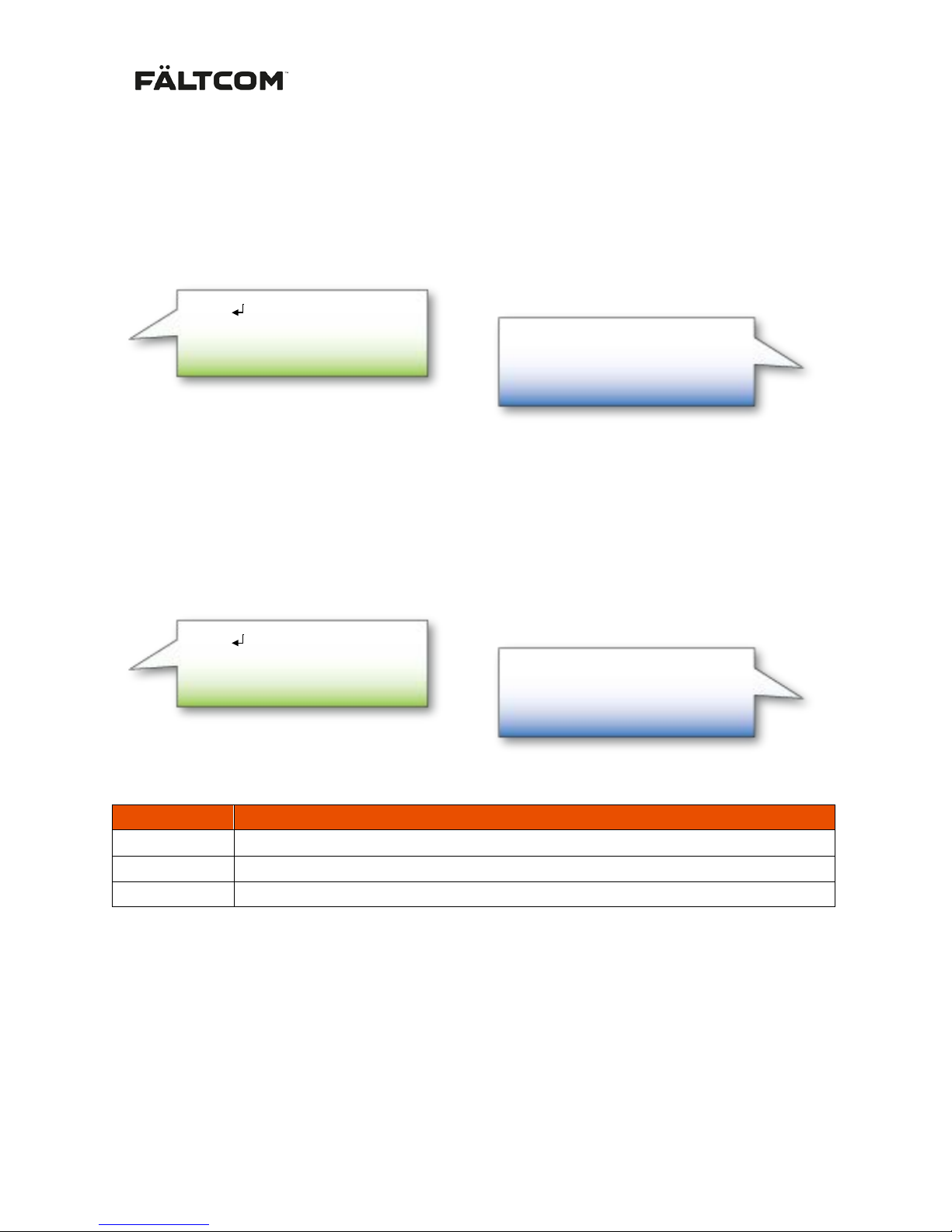
Reset the Gateway sending a “Reset” SMS. The SMS must contain the SMS Access code followed by
a new line and the word Reset. The default Access code is 1111 and c an be changed using the
Fältcom Manager SW.
If the Gateway receives a correct request, the Gateway will restart. If the restart is successful the
Gateway will return an acknowledgement as below, where SN: is the serial number of the Gateway.
5.5 Ask for the current Gain
Get the current Gain of the Gateway by sending a “Gain” SMS. The SMS must contain the SMS
Access code followed by a new line and the word Gain. The default Access code is 1111 and can be
changed using the Fältcom Manager SW.
If the SMS is correct the Gateway will return the Gain settings.
Description table of the gain SMS:
Parameter
Description
SN
Serial number of the Gateway
GSM->POTS
Gain parameter for signals from alarm receiver to Flex (4-(-20))
POTS->GSM
Gain parameter for signals from Flex to the alarm receiver (3-(-20))
5.6 Change the Gain
To change the Gain of the Gateway, send SMS as follows below. The SMS must contain the SMS
Access code. The default Access code is 1111 and can be changed using t he Fältcom Manager SW.
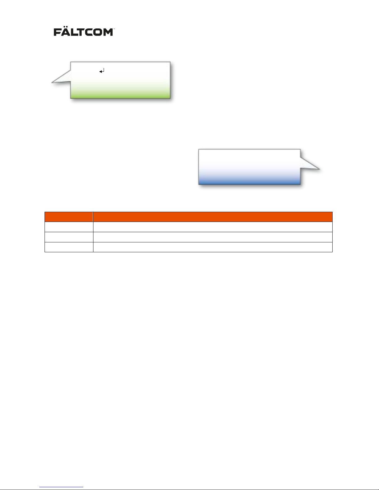
To change the gain, send SMS:
1111
Reset
SMS to GSM Gateway:
SN:V12345
Reset successful
SMS acknowledgement from GSM Gateway:
1111
Gain
SMS to GSM Gateway:
SN:V12345
Gain
GSM->POTS: x
POTS->GSM: y
SMS acknowledgement from GSM Gateway:
Page 14
162236M User Manual GSM Gateway Page 14 of 20
The SMS can contain either one or both GSM and POTS settings.
If the Gateway receives a correct request, the Gateway will answer the the new Gain settings:
Description table of the gain SMS:
Parameter
Description
SN
Serial number of the Gateway
GSM->POTS
Gain parameter for signals from alarm receiver to Flex (4-(-20))
POTS->GSM
Gain parameter for signals from Flex to the alarm receiver (3-(-20))
If the received parameters are outside the range, the Gateway will set the highest or lowest level. That
is, if the received GSM->POTS is 5 then the Gateway will set the gain to 4 and if the received POTS>GSM is -24 then the Gateway will set the gain to -20.
1111
Gain
GSM->POTS: x
POTS->GSM: y
SMS to GSM Gateway:
SN:V12345
Gain
GSM->POTS: x
POTS->GSM: y
SMS acknowledgement from GSM Gateway:
Page 15
162236M User Manual GSM Gateway Page 15 of 20
6. Upgrade Tool
The USB interface is used to configure user specific parameters and to upgrade the GSM G at eway
firmware. The upgrade requires the Windows program “Fältcom Manager” and is available from
Fältcom or your local distributor. Use a standard USB – mini USB cable to connect the GSM Gateway
to the PC.
- Install the “Fältcom Manager” tool on your PC.
- Connect the GSM Gateway to t he PC using a standard USB – mini-B USB cable.
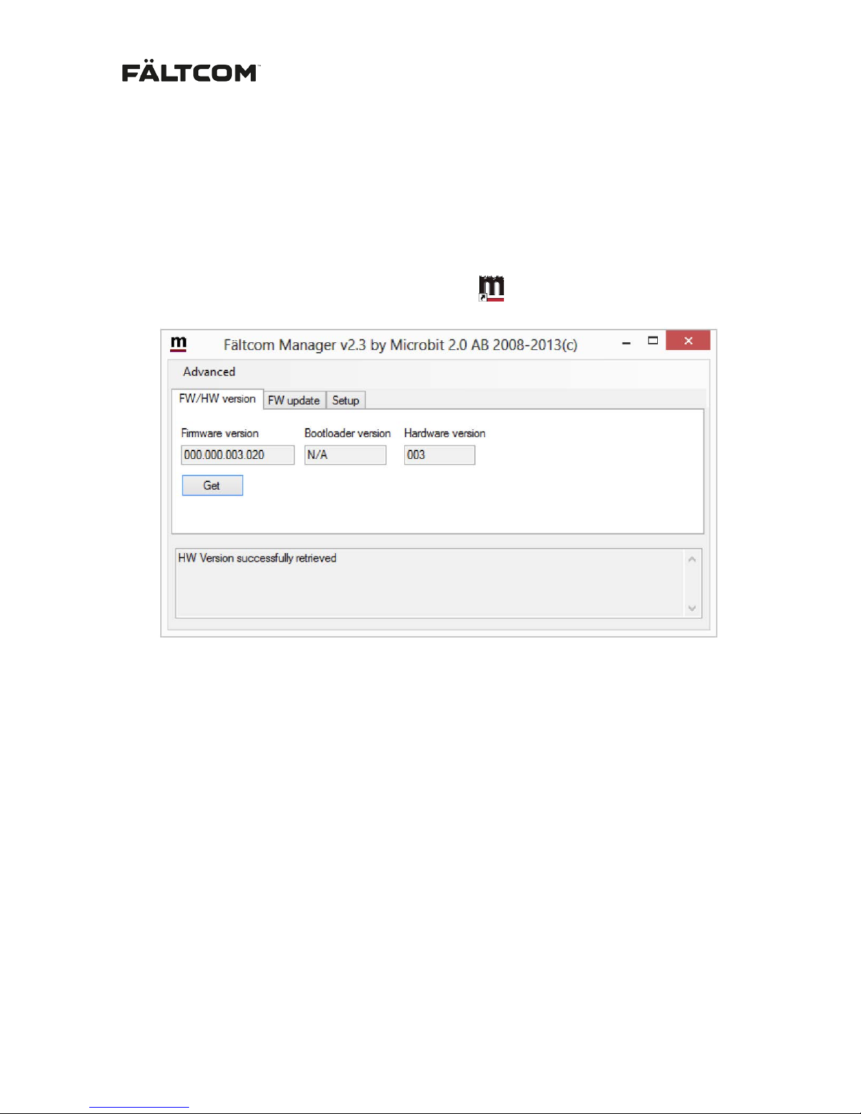
- Start the “Fältcom Manager” by clicking the icon
When the GSM Gateway is connected to the Manager tool the status bar at the bottom will show
“1258 connected”
Push “Get” to see the GSM Gateway Firmware and Hardware versions. In this example FW 3.20 and
HW 003.
Page 16
162236M User Manual GSM Gateway Page 16 of 20
6.1 Firmwa re upgrade
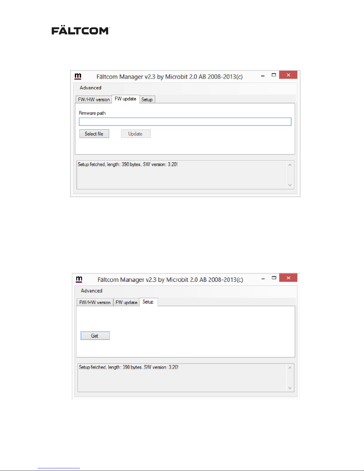
To upgrade the GSM Gateway Firmware select the “FW update” tab.
- Click on “Select file”
- Browse to find and select the new FW file supplied by Fältcom or your local distributor.
Note: The FW file always has the file extension .bin (e.g. gatewayFW.bin).
- Click on “Update”. During the update you can follow the progress in the status bar.
Note: Be careful not to disconnect the power during FW upgrade.
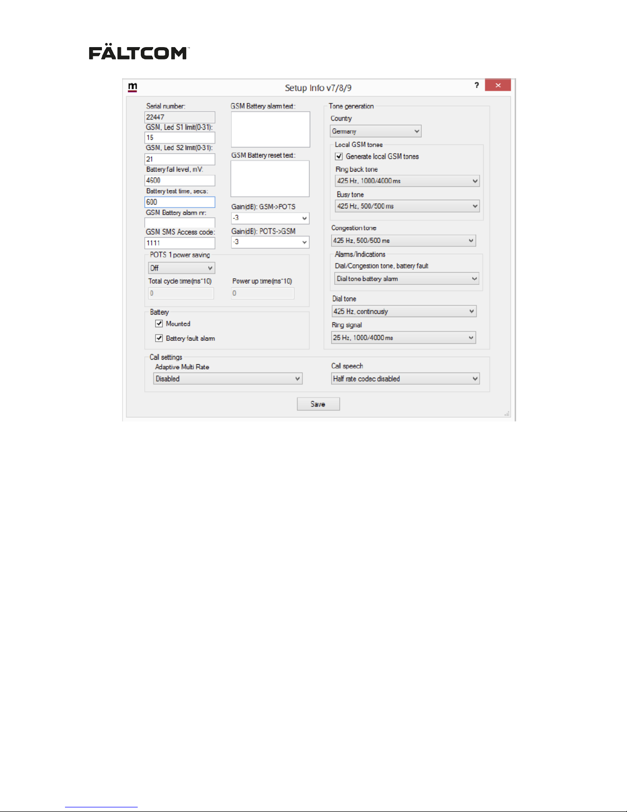
6.2 Setup
For configuration of user specific settings use the “Setup” tab and click on “Get setup”
A new window will appear showing all configurable settings.
Page 17
162236M User Manual GSM Gateway Page 17 of 20
6.2.1 LED control on signal strength
There are two LED’s showing the strength of the GSM signal; S1 and S2. You can set the limits when
the LED should be lit.
6.2.2 Battery control
The GSM Gateway can be used with or without battery backup. The default setting is battery Mounted
and Battery fault alarm enabled.
The Battery fault alarm can be disabled by unchecking the Battery fault alarm box. This setting will
disable the Battery fault alarm but still charge the battery.
If the lift has a battery backup system the battery in the Gateway can be rem oved, uncheck the
Mounted battery box to disable all battery charge, test and alarm.
6.2.3 Battery SMS
For information on th e battery SMS please see the section 4 Battery.
- Fill out the “GSM Battery alarm nr”; the telephone number where to receive battery alarm SMS.
- Fill out the “GSM Battery alarm text”; SMS text from the Gateway in case of battery alarm.
E.g. Low voltage on battery from lift 4435.
- Fill out the “GSM Battery reset text”; SMS text from the Gateway when the battery is replaced.
E.g. Low voltage battery reset from lift 4435.
Page 18

162236M User Manual GSM Gateway Page 18 of 20
6.2.4 GSM SMS Access code
Change the SMS Access code. The SMS Access code is used as an authorisation code for the
Gateway to send SMS to the user. If the Access code in the SMS sent to the Gateway is incorrect, the
Gateway will not answer the SMS.
6.2.5 Gain control
Gain control is used to amplify or attenuate the signals between the GSM network and t he PHONE
line from the Gateway to the emergency alarm. The signal gain can be set on both GSM to POTS and
POTS to GSM. Please note that POTS is the analogue line PHONE generated by the GSM Gateway.
Changing the GSM to POTS (PHONE) to positive values wi ll am plify the signal received on the GSM
transmitted to the PHONE. Changing to negative values will attenuate the signals to the PHONE.
Changing the POTS (PHONE) to GSM to positive values will amplify the signal received from the
PHONE transmitted to the GSM network. Changing to negative values will attenuate the signals to the
GSM network.
The signal gain and quality of the GSM system differs between countries and you may t heref ore be
required to change the signal gain to adjust for these differences. If the emergency alarm has trouble
receiving and deciphers DTMF sent by the receiver; try adjusting the GSM to POTS (PHONE). Start
by trying negative values, if the result does not improve; try positive values.
If the receiver has trouble receiving and deciphers DTMF sent by the emergency alarm; try adj usting
the POTS (PHONE) to GSM.
6.2.6 POTS1 power saving
Note: Do not use this feature for any emergency alarm systems. This feature can be used when
connecting the Gateway to a regular phone.
The power save will disconnect the PHONE line power during a pre-defined time. Operating modes
are “Off”, “Always on” and “Battery only”.
Battery only mode will enable the function only during battery operation to increase the battery
operation time.
After selecting operating mode; set:
Total cycle time – Cycle time for power save operation. E.g. select cycle time to 1 second; set the
Total cycle time (ms*10/steps) to 100 (=1000ms).
Power up time – Time of operation during the cycle time. E.g. if the cycle time is set to 1 second and
you want the Gateway to power the PHONE during 50% of the time; set the Power up time
(ms*10/steps) to 50 (=500ms).
6.2.7 Tone generation
The GSM Gateway can generate line tones on the PHONE line according to different country specific
preferences. There are a few pre-programmed countries:
France, Germany, Great Britain, Italy and Spain.
Germany and Italy have the same settings, which is also the EU recommendation for PSTN line tones.
When using the GSM Gateway with an emergency phone; please use German, Italian or Spanish
settings even if installed in other countr ies.
6.2.8 Battery failure signal – Dial ton e battery alarm
The Gateway can signal a battery failure by signalling on the PHONE analogue line.
Page 19

162236M User Manual GSM Gateway Page 19 of 20
Setting the GSM Gateway to generate the Dial tone battery alarm, indicating a battery failure. When a
battery failure occurs the Gateway will send a congested tone instead of the normal continuous dial
tone. The Dial tone battery alarm is 1000ms ON / 250ms OFF / 250ms ON / 250ms OFF. To configure
this setting set:
“Dial/Congestion tone, battery fault” to “Dial tone battery alarm”.
This setting is default active.
The emergency alarm must be programmed accordingly in order to detect the battery fault alarm
signal from the Gateway; please see the manual for the emergency alarm if that setting is available.
7. Technical Data
Parameter: Data:
Size (L x B x H): 165 x 140 x 25 mm
Weight: 558 g, with battery and antenna included
Protection class: IP 20
External power: 10-28 VDC
Power consumption At rest: 12V < 180mA, 2 4V < 95mA
O ngoing call: 12V < 330mA, 24V < 160mA
Battery type: NiMH 4,8V 1250mAh
Battery power consumption: At rest: < 120 mA. Ongoing call: < 300 mA
I . E. 2h including 3 x 3 minute calls.
GSM module: Siemens M55i-W (Quad-Band 850/900/1800/1900 MHz)
Antenna: 50 Ohm, 2dBi gain, SMA-connector, 880–960 MHz/1710–1990 MHz
Line voltage on hook: 42 V DC
Polarity reversal: Yes
Operating temperature: +5 °C to +40 °C
Air humidity: 30 % to 90 % RH
Tone indications
Dial tone: 425 Hz -10 dBm. Continuous
Dial tone battery alarn: 425 Hz -10dBm. 1000ms ON / 250ms OFF / 250ms ON / 250ms OFF,
continuous
Congestion tone: 425 Hz -10dBm. 200ms ON / 200ms off / 200ms ON / 200ms OFF /
200ms ON / 600ms OFF, continuous
Ringing signal: 25 Hz 40 VRms into 3REN. 1000 ms ON / 4000 ms OFF
Ring back tone: 425Hz, 1000 ms ON / 4000 ms OFF
Busy tone: 425Hz, 500 ms ON / 500 ms OFF
Connections
Telephone: RJ-11
Antenna connector: SMA
DC power supply input DC Plug 2.1mm/5.5mm
USB: USB 2.0 Mini
Page 20

162236M User Manual GSM Gateway Page 20 of 20
8. Repair return procedure
Fält Communications AB only accepts returns that have a valid a RMA number. Please contact Fält
Communications AB support to receive a RMA number.
Repaired products are sent back to customers as a regular post parcel with freight paid on the
assumption that the product is covered by warranty. If the investigation shows that the re-turned
product has no defects the customer is charged a service fee and freight. The customer can ask for a
quotation for repair of product not covered by warranty.
9. Contact Information
Support:
Tel:+ 46 (0)90 18 39 27
E-mail: [email protected]
Fält Communications AB
Vasagatan 23
SE-903 29 UMEÅ, Sweden
Phone: + 46 (0)90 18 39 00
Fax: + 46 (0)90 18 39 29
Homepage: www.faltcom.com
 Loading...