

Page 1

LIBRETTO ISTRUZIONI
INSTRUCTIONS BOOKLET
BEDIENUNGSSANLEITUNG
LIVRET D’INSTRUCTIONS
MANUAL DE INSTRUCCIONES
азлнкмдсаь ий щдлигмДнДсаа
INSTRUKCJE OBSŁUGI
Cod. 110030253 (MIRABILIA)
Ed. 2011
Page 2

Gentile Signora/Signore, congratulazioni!
Lei ha acquistato una cappa di prestigio e di sicura qualità. Perché Lei possa ottenere
le migliori prestazioni, Le suggeriamo di seguire con attenzione le istruzioni per l’uso e
manutenzione che troverà in questo libretto; inoltre, per ordinare i filtri di ricambio al
carbone attivo utilizzi l’apposito tagliando che troverà allegato alla copertina.
Dear Sir/Madam, congratulations!
You have purchased a prestigious range hood of guaranteed quality. For best results, we
suggest that you carefully follow the operating and maintenance instructions provided in this
booklet; in addition, to order spare charcoal filters, use the special coupon on the cover.
Verehrte Kundin, verehrter Kunde
Kompliment! Sie haben eine qualitativ hochwertige Dunstabzugshaube erworben. Um ihre
Leistungsfähigkeit optimal nutzen zu können, sollten Sie die beiliegende Gebrauchs- und
Wartungsanleitung sorgfältig durchlesen und befolgen. Für die Bestellung der ErsatzAktivkohlefilter verwenden Sie bitte den Coupon, der dem Deckblatt beiliegt.
Chère Madame/Cher Monsieur, félicitations!
Vous venez d’acheter une hotte haut de gamme. Pour en tirer les performances les
meilleures veuillez lire avec attention le mode d’emploi et la maintenance que vous trouvez
dans ce manuel ; pour commander les filtres de rechange au carbone actif veuillez vous
servir du coupon annexé à la couverture.
Enhorabuena Señora/Señor!
Ha comprado una campana extractora de prestigio y calidad segura. Para que pueda
obtener las mejores prestaciones, le sugerimos seguir con atención las instrucciones
contenidas en este manual para el uso y el mantenimiento. Para pedir los filtros de recambio
de carbón activo, utilice el cupón adjunto a la cubierta.
З˚ ФЛУ·ОЛ ФТЪЛКМУ Л ‚˚ТУНУН‡˜ТЪ‚ММУ ‚˚ЪflКМУ ЫТЪУИТЪ‚У. СОfl ЪУ„У,
˜ЪУ·˚ УМУ ‰‡‚‡ОУ М‡ЛОЫ˜¯Л БЫО¸Ъ‡Ъ˚, НУПМ‰ЫП ‚МЛП‡ЪО¸МУ ТО‰У‚‡Ъ¸
ЛМТЪЫНˆЛflП ФУ ˝НТФОЫ‡Ъ‡ˆЛЛ Л ЫıУ‰Ы, НУЪУ˚ ‚˚ М‡И‰Ъ ‚ ˝ЪУП ЛБ‰‡МЛЛ;
НУП ЪУ„У, ‰Оfl Б‡Н‡Б‡ Б‡Ф‡ТМ˚ı ЩЛО¸ЪУ‚ М‡ ‡НЪЛ‚ЛУ‚‡ММУП Ы„О ЛТФУО¸БЫИЪ
ТФˆЛ‡О¸М˚И Ъ‡ОУМ, НУЪУ˚И ‚˚ ПУКЪ М‡ИЪЛ ФЛНФОММ˚П Н У·ОУКН.
Szanowni Państwo
Gratulujemy!
Zakupiliście prestiżowy okap kuchenny o gwarantowanej jakości. Dla uzyskania
najlepszych wyników zalecamy, by starannie przestrzegać instrukcji obsługi i
konserwacji zawartych w tej broszurze. Ponadto, do zamawiania zapasowych fi ltrów
z węglem drzewnym, wykorzystywać specjalny kupon załączony na okładce.
Page 3
MIRABILIA PARETE/WALL
SUCTION
VERSION
(25,6”)
650 mm
MIRABILIA ISOLA/ISLAND
RECIRCULATION
VERSION
(25,6”)
650 mm
Fig. C1
(25,6”)
650 mm
(25,6”)
650 mm
Fig. C2
1
Page 4
MIRABILIA PARETE/WALL
Predisposizione solo per versione con evacuazione posteriore
Only for back outlet version
Step 1
Step 2
Step 3
Vista posteriore Mirabilia Wall / Rear view Mirabilia Wall
280,5
226,1
155
2
Page 5
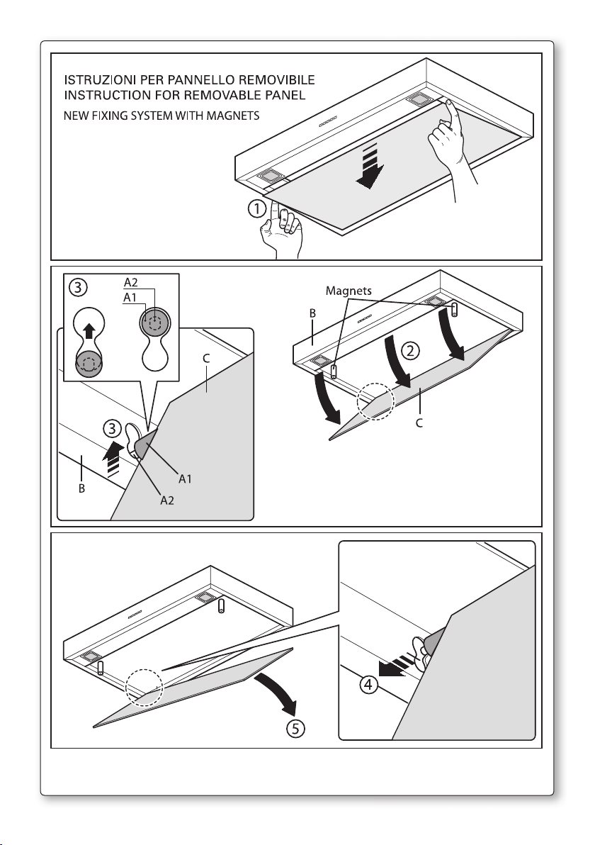
Fig. H3
3
Page 6
MIRABILIA PARETE/WALL
X 300
A
Fig. O1
B
C
Fig. O2
V1
H
V2
E
F
G
D
Fig. O4
Fig. O3
4
Page 7
ISTRUZIONI MONTAGGIO/SMONTAGGIO VETRI
MOUNTING INSTRUCTIONS FOR THE GLASSES
MIRABILIA 67 - MIRABILIA 97
ISOLA/ISLAND 67 CENTRAL CHIMNEY
A
B
B 1
B
V 1
A (1 : 1)
B (1 : 1)
MIRABILIA ISOLA/ISLAND 85
Fig. O5
5
Page 8
C2
H1
H
H2
Ø8
Ø8
C1
C
V1 (x4)
Fig. 1a
Fig. 1b
H1= 650 mm (25,6”)
V2 (x8)
C+C1
V3(x4)
A
F
D+E
MIRABILIA ISOLA/ISLAND 85
ISOLA/ISLAND 67 CENTRAL CHIMNEY
Fig. 1 Fig. 2
6
Page 9
MIRABILIA ISOLA/ISLAND 85 - ISOLA/ISLAND 67 CENTRAL CHIMNEY
Fig. 3
V3
3d
V3
V3 (x4)
3d
F
3c
3e
3a
3a
3i
V5 (x2)
3f
3a
V4 (x4)
3b
3g
7
Page 10
I
LIBRETTO ISTRUZIONI
A
Se l’apparecchio dovesse essere venduto o trasferito ad un’altra persona,
Queste avvertenze sono state redatte per la vostra sicurezza e per quella degli
AVVERTENZE
È molto importante che questo libretto istruzioni sia conservato insieme al-
l’apparecchiatura per qualsiasi futura consultazione.
assicurarsi che il libretto venga fornito assieme, in modo che il nuovo utente
possa essere messo al corrente del funzionamento della cappa e delle avvertenze relative.
altri, Vi preghiamo, dunque, di volerlo leggere attentamente prima d’installare
e di utilizzare l’apparecchio.
Questo apparecchio non deve essere utilizzato da bambini o persone infermi
a meno che non siano adeguatamente controllate da persone responsabili che
si assicurino che l’apparecchio sia utilizzato in sicurezza.
I bambini devono essere controllati da persona responsabile per assicurarsi
che non giochino con l’apparecchio.
Il lavoro di installazione deve essere eseguito, da installatori competenti e
qualificati, secondo le norme in vigore.
Se il cavo di alimentazione è danneggiato, esso deve essere sostituito dal
costruttore o dal suo servizio assistenza tecnica o comunque da una persona
con qualifica similare, in modo da prevenire ogni rischio.
Ogni eventuale modifica che si rendesse necessaria all’impianto elettrico per
installare la cappa dovrà essere eseguita solo da persone competenti.
È pericoloso modificare o tentare di modificare le caratteristiche di questo
impianto. In caso di riparazioni o mal funzionamento dell’apparecchio, non
tentare di risolvere da soli il problema.
Le riparazioni effettuate da persone non competenti possono provocare danni.
Per eventuali interventi rivolgersi ad un Centro Assistenza Tecnica autorizzato
ad eseguire parti di ricambio.
Controllare sempre che tutte le parti elettriche, (luci, aspiratore), siano spente
quando l’apparecchio non viene usato. Leggere tutto il libretto istruzioni prima di effettuare operazioni sulla cappa.
L’utilizzo della cappa non può essere diverso da quello di aspiratori di fumi di
cottura su cucine domestiche.
Qualsiasi utilizzo diverso da questo solleva il costruttore da qualsiasi responsabilità.
Il peso massimo complessivo di eventuali oggetti posizionatio appesi (ove
previsto) sulla cappa non deve superare 1,5 Kg.
Dopo l’installazione delle cappe in acciaio inox bisogna eseguire la pulizia
della stessa per rimuovere i residui di collante protettivo e le eventuali macchie di grasso o oli.
Per questa operazione il costruttore raccomanda l’utilizzo delle salviette in
dotazione, disponibili anche in acquisto.
L’utilizzo di altre tipologie di detergenti solleva il costruttore dalla responsabilità sui danni che ne potrebbero derivare.
8
Page 11

B
CARATTERISTICHE TECNICHE
I dati tecnici dell’elettrodomestico sono riportati su delle targhette, posizionate all’interno della cappa.
C
D
INSTALLAZIONE
(parte riservata solo a persone qualificate per il montaggio della cappa)
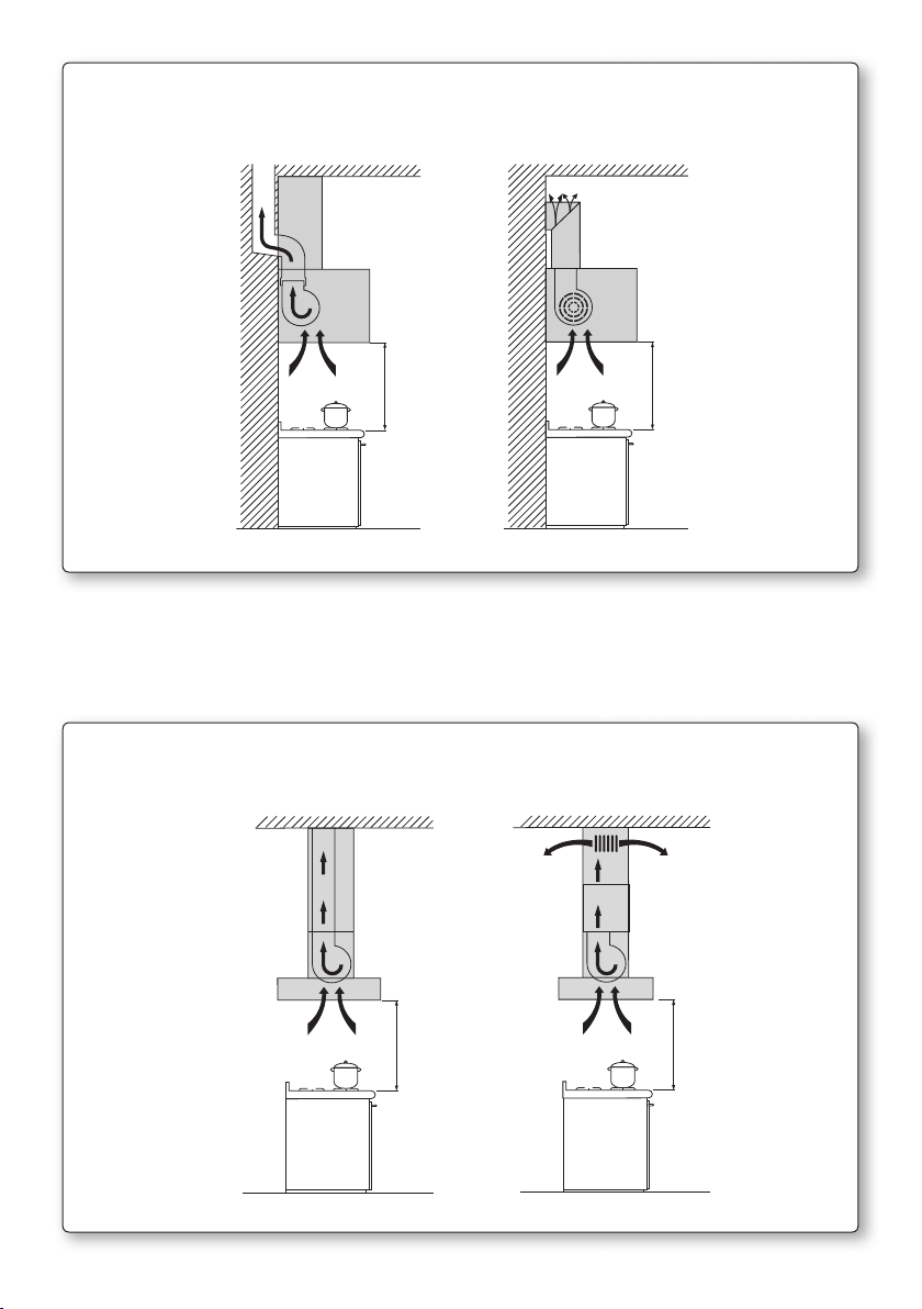
La distanza fra il piano cottura e la parte più bassa della cappa da cucina è di
norma almeno 65 cm (vedi figura C1). Tale distanza è misurata a rigore nel
punto più basso della cappa con tensione non di sicurezza. Sulla base di questa
dettaglio previsto dalle norme Europee è possibile ridurre la distanza su alcuni
modelli come specificato nel catalogo generale. Se le istruzioni del piano di cottura a gas specificano una distanza maggiore, bisogna tenerne conto.
Nella versione aspirante il tubo di uscita dei fumi deve avere un diametro non
inferire a quello del raccordo della cappa.
Nei tratti orizzontali il tubo deve avere una leggera inclinazione (10% circa)
verso l’alto per convogliare l’aria all’esterno dell’ambiente.
Ridurre al minimo le curve, verificare che i tubi abbiano una lunghezza minima indispensabile.
Rispettare le norme vigenti sullo scarico dell’aria all’esterno.
In caso di utilizzo contemporaneo di altre utenze (caldaie, stufe, caminetti,
ecc.) alimentate a gas o con altri combustibili, provvedere ad una adeguata
ventilazione del locale in cui avviene l’aspirazione dei fumi, secondo le norme
vigenti.
Istruzioni di montaggio: vedi sez. “O” del presente manuale.
ALLACCIAMENTO ELETTRICO
(parte riservata solo a persone qualificate per l’allacciamento)
ATTENZIONE!
Prima di effettuare qualsiasi operazione all’interno della cappa scollegare
l’apparecchio dalla rete elettrica.
Assicurarsi che non vengano scollegati o tagliati fili elettrici all’interno della
cappa; nel caso si verifichino tali situazioni contattare il centro assistenza più
vicino. Per l’allacciamento elettrico rivolgersi a personale qualificato.
Il collegamento deve essere eseguito in conformità con le disposizioni di
legge in vigore. Controllare che la valvola limitatrice e l’impianto elettrico
possano sopportare il carico dell’apparecchio (vedere targhetta caratteristiche
tecniche al punto B). Alcuni tipi di apparecchi possono essere dotati di cavo
senza spina; in questo caso, la spina da utilizzare deve essere dei tipo “normalizzato” tenendo conto che:
- il filo giallo-verde deve essere utilizzato per la messa a terra,
- il filo blu deve essere utilizzato per il neutro,
- il filo marrone deve essere utilizzato per la fase, il cavo non deve entrare in
contatto con parti calde aventi temperature superiori a 70 °C.
- montare sul cavo di alimentazione una spina adatta al carico e collegarla ad
9
Page 12
una adeguata spina di sicurezza.
Se un apparecchio fisso non è provvisto di cavo di alimentazione e di spina, o
di altro dispositivo che assicuri la disconnessione dalla rete, con una distanza
di apertura dei contatti che consenta la disconnessione completa nelle condizioni della categoria di sovratensione III, le istruzioni devono indicare che tali
dispositivi di disconnessione devono essere previsti nella rete di alimentazione conformemente alle regole di installazione.
Il cavo di terra giallo/verde non deve essere interrotto dall’interruttore.
Prima di collegare l’apparecchio alla rete elettrica, controllare che:
- la tensione d’alimentazione corrisponda a quella indicata dalla targhetta
caratteristiche tecniche.
- la presa di terra sia corretta e funzionale.
- l’impianto di alimentazione sia munito di efficace collegamento di terra secondo le norme vigenti.
- la presa o l’interruttore omnipolare usati siano facilmente raggiungibili con
l’apparecchiatura installata.
La casa costruttrice declina ogni responsabilità nel caso le norme di sicurezza
non vengano rispettate.
E
CAPPA IN VERSIONE
AD EVACUAZIONE ESTERNA (aspirante)
In questa versione i fumi e i vapori della cucina vengono convogliati verso
l’esterno attraverso un tubo di scarico.
Il convogliatore di scarico che sporge sulla parte superiore della cappa deve essere collegato con un tubo che conduce i fumi e i vapori in una uscita
esterna.
In questa versione vanno tolti i filtri al carbone attivo se esistenti; per l’estrazione vedere istruzioni al punto F. Quando la cappa da cucina viene utilizzata
contemporaneamente ad altri apparecchi che impiegano gas o altri combustibili, il locale deve disporre di sufficiente ventilazione secondo le norme
vigenti.
Deviazione per la Germania:
Quando la cappa da cucina e apparecchi alimentati con energia diversa da
quella elettrica sono in funzione simultaneamente, la pressione negativa nel
locale non deve superare i 4 Pa (4 x 10⁻⁵ bar).
F
CAPPA IN VERSIONE
A RICICLO INTERNO (filtrante)
In questa versione l’aria passa attraverso i filtri di carbone attivo per essere
purificata e viene riciclata nell’ambiente cucina.
Controllare che i filtri al carbone attivo siano montati sul motore, in caso negativo applicarli come indicato nelle istruzioni al punto H.
Se la cappa viene predisposta in versione filtrante rimuovere la valvola di non
ritorno montata sul raccordo di uscita del motore.
10
Page 13
Per il miglior rendimento si consiglia di utilizzare la terza velocità in presenza
di forti odori e vapori, la seconda velocità nelle condizioni normali, la prima
velocità per mantenere l’aria pulita con bassi consumi di energia elettrica.
Si consiglia di mettere in funzione la cappa quando si inizia a cuocere e manteneria in funzione fino alla scomparsa degli odori.
G
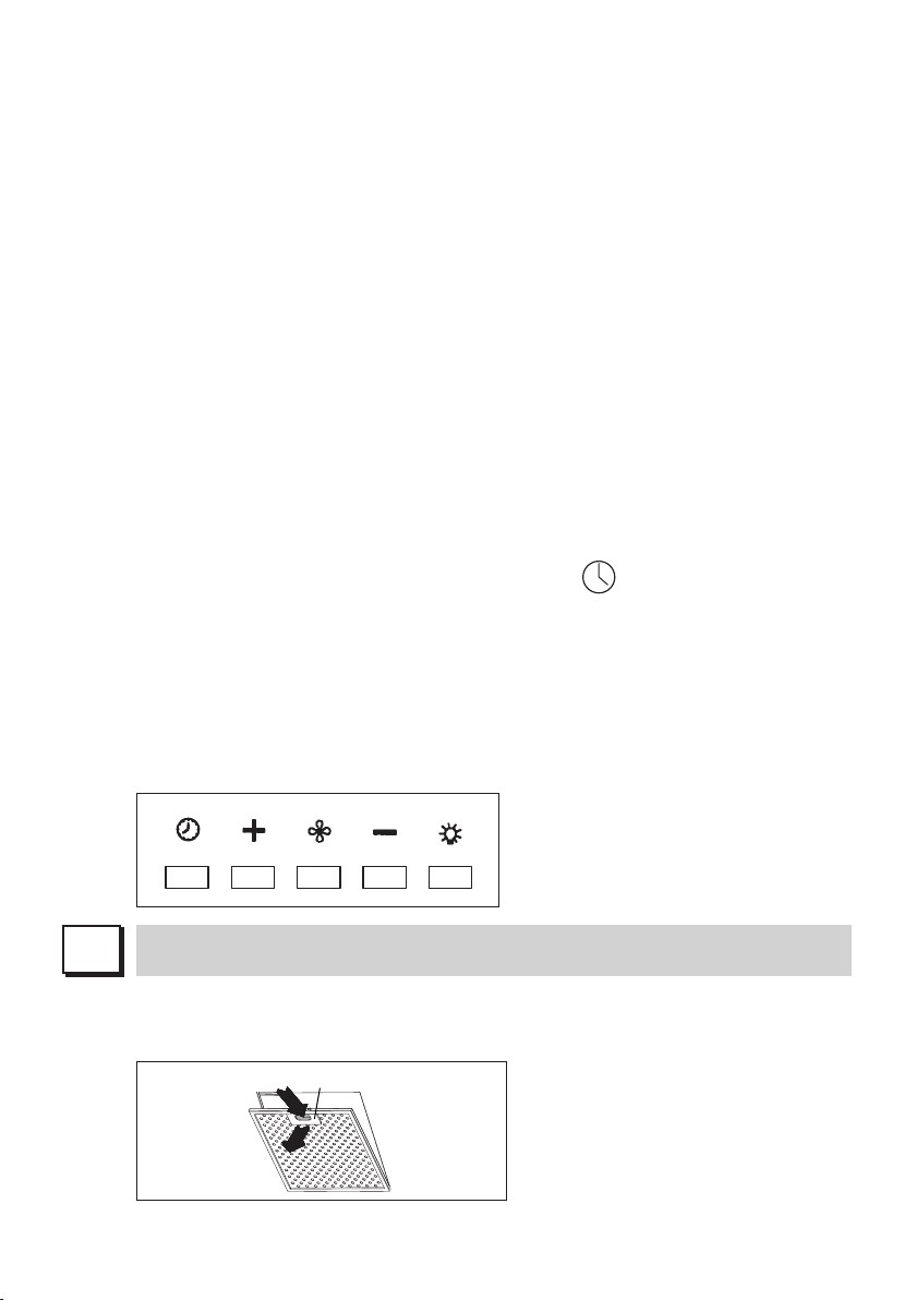
FUNZIONAMENTO
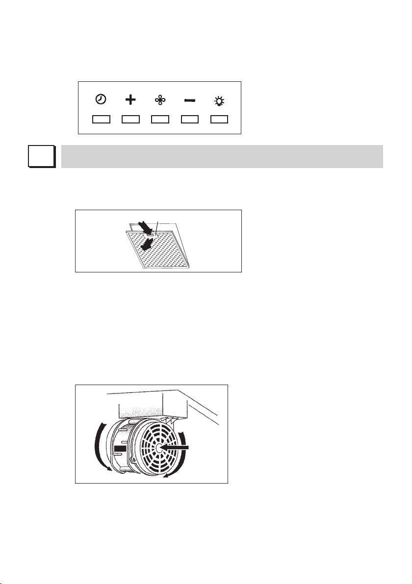
PULSANTIERA ELETTRONICA
Pulsante luce
• ON: luce accesa (pulsante illuminato);
• OFF: luce spenta;
Dimmer con funzioni integrate nella tastiera: con motore spento e con una
pressione lunga tasto luce (2 secondi) della tastiera si accede alla modalità
modifica intensità luce di atmosfera (lampade ad incandescenza o led).
Agendo sui tasti + e – si regola l’intensità della luce. Con motore avviato
la pressione lunga del tasto accende o spegne la luce di atmosfera.
Pulsante -
Premendo il tasto si riduce la velocità del motore.
La velocità 1, 2 e 3 è visualizzata dal n° di led accesi escluso led luce e
timer.
Pulsante +
Premendo il tasto si incrementa la velocità del motore.
La velocità 1,2 e 3 è visualizzata dal n° di led accesi escluso led luce e ti-
mer.
(Nella versione a 4 velocità il tasto + presenta una luce intermittente. La 4°
velocità o intensiva è temporizzata e dopo circa 15 minuti il motore passa
automaticamente in 3° velocità).
Pulsante modalità
Funzione: accensione e spegnimento motore cappa.
La funzione velocità desiderata permette di avviare il motore con l’ultima
velocità selezionata prima del precedente spegnimento.
Optional: versione con radiocomando (disponibile solo su alcune versioni).
AVVERTENZE (versione con radiocomando):
Posizionare l’apparecchio lontano da sorgenti di onde elettromagnetiche
che potrebbero interferire con l’elettronica della cappa.
Distanza massima di funzionamento 5 metri. Tale distanza può variare in
difetto in funzione delle interferenze elettromagnetiche di altri apparecchi.
Pulsante luce del telecomando: on/off luce.
Pulsante – e + decremento/incremento velocità (per avviare il motore pre-
mere indifferentemente tasto + o in tasto -.
Pulsante timer: vedi istruzione sottostante.
Pulsante timer e saturazione filtri
- Questa funzione permette lo spegnimento automatico della cappa dopo
15 minuti di funzionamento alla velocità precedentemente impostata (pul-
sante con luce intermittente).
11
Page 14
- Dopo circa 30 ore di funzionamento il pulsante propone il lavaggio dei fil-
tri metallici (pulsante illuminato di rosso). Per disattivare l’allarme preme-
re il pulsante timer per qualche secondo fino allo spegnimento della luce
rossa. Successivamente spegnere la cappa e riaccenderla per verificare
l’annullamento dell’allarme.
H
FILTRI ISTRUZIONI PER L’ESTRAZIONE E LA SOSTITUZIONE
1. FILTRI METALLICI
- Aprire il pannello (vedi fig. H3). Per rimuovere il filtro metallico antigrasso
agire sulla maniglia A.
A
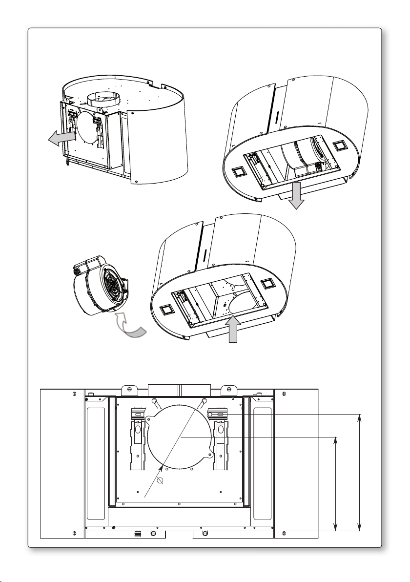
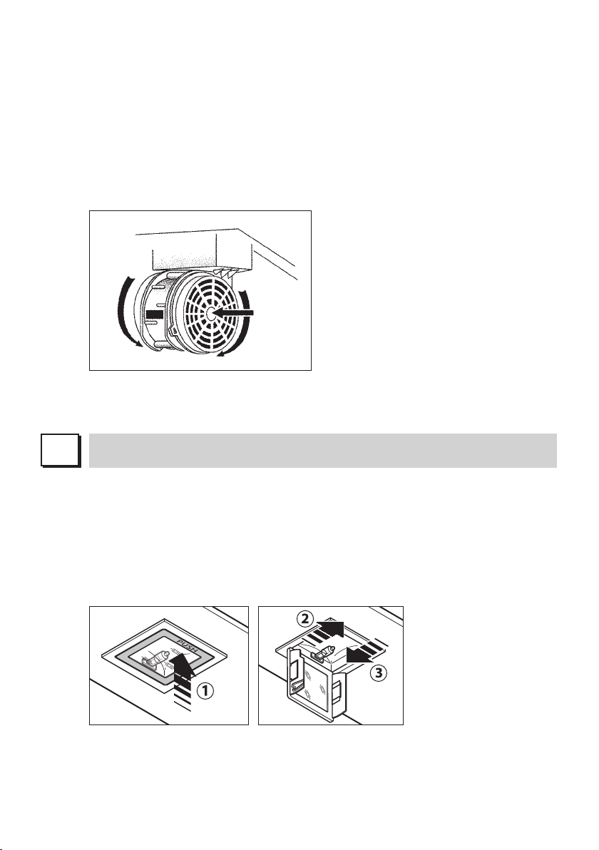
2. FILTRI AL CARBONE ATTIVO
Per la sostituzione dei filtri al carbone attivo si proceda come segue: toglie-
re i filtri metallici come indicato sopra. A questo punto si accede facilmen-
te ai due filtri che sono agganciati sul lato dx e sx del convogliatore.
Per il montaggio/sostituzione vedi figura.
Nel caso di cappa con camera motore il filtro è posizionato nella parte
inferiore della camera stessa. Per il montaggio/sostituzione vedi figura.
Per ordinare i nuovi filtri carbone rivolgersi al distributore/rivenditore.
SOLO PER ITALIA: Scaricare l’apposito modulo ordine filtro sul sito: www.
falmec.com (accedere sul menù a tendina assistenza).
12
3. PANNELLO REMOVIBILE
Per rimuovere il pannello seguire l’istruzione in fig. H3
Page 15
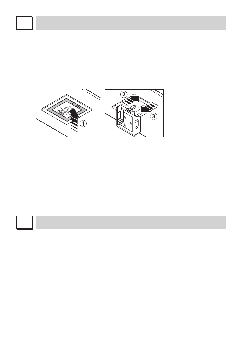
ILLUMINAZIONE MONTAGGIO E SOSTITUZIONE
I
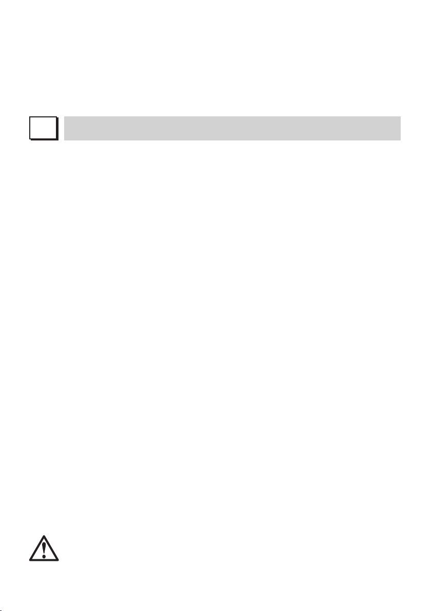
FARETTO
Per sostituire la lampada del “Square halogen light”:
a) Accertarsi che l’apparecchio sia scollegato dalla rete elettrica.
b) Aprire completamente il pannello fino ad un angolo di 90° (vedi figura) pre-
mendo su PUSH
c) Sostituire la lampada con una analoga (alogena max 20 W, 12 Volt attacco
G4).
d) Richiudere i pannello. Se il pannello non si richiude correttamente ripetere
l’operazione al punto b.
Square halogen light
ILLUMINAZIONE DEI VETRI
Per sostituire la lampada ad incandescenza:
1) accertarsi che la cappa sia scollegata dalla rete elettrica;
2) rimuovere i vetri decorativi (vedi sez. O);
3) sostituire la lampadina con una dello stesso modello di quella originale
(max. 25W);
4) rimontare i vetri (vedi fig. O5).
Nel caso di cappe con illuminazione a led la sostituzione del corpo luminoso
può essere fatta solo da personale specializzato e con ricambi originali.
AVVERTENZA: Non rimuovere i vetri se i led di illuminazione dei vetri sono
accesi.
L
Una costante manutenzione garantisce un buon funzionamento ed un buon
MANUTENZIONE E PULIZIA
rendimento nel tempo. Particolari attenzioni vanno rivolte ai filtri metallici
antigrasso ed ai filtri al carbone attivo, infatti la pulizia frequente dei filtri e dei
loro supporti garantisce che sulla cappa non si accumulino grassi che sono
pericolosi per la facilità di incendio.
1. FILTRI ANTIGRASSO METALLICI
Hanno la funzione di trattenere le particelle grasse in sospensione, pertanto
si consiglia di lavarli ogni mese in acqua calda e detersivo evitando di pie-
garli. Attendere che siano ben asciutti prima di rimontarli.
Per lo smontaggio e montaggio vedi istruzioni al punto H1. Si raccomanda
costante frequenza nell’operazione.
2. FILTRI AL CARBONE ATTIVO
Hanno la funzione di trattenere gli odori presenti nel flusso d’aria che li
attraversa. L’aria depurata per successivi passaggi attraverso i filtri viene
rimessa nell’ambiente cucina. l filtri al carbone attivo non possono essere
13
Page 16
lavati e vanno sostituiti mediamente ogni 3-4 mesi (dipende poi dall’uso).
Per la sostituzione dei filtri al carbone attivo seguire le istruzioni come al
punto H2.
3. PULIZIA ESTERNA
Si raccomanda di pulire le superfici esterne delle cappe almeno ogni 15
giorni per evitare che le sostanze oleose o grasse possano intaccare le
superfici in acciaio.
La pulizia della cappa va eseguita usando un panno umido con detersivo
liquido neutro o con alcool denaturato.
Nel caso di materiale con trattamento antimpronta (Fasteel) eseguire la pu-
lizia solo con acqua e sapone neutro utilizzando un panno morbido avendo
cura di risciacquare e asciugare accuratamente. Non si devono utilizzare
prodotti contenenti sostanza abrasive, panni con superfici ruvide o panni
comunemente in commercio per la pulizia dell’acciaio. L’utilizzo di sostanze
abrasive e panni ruvidi danneggerà irreparabilmente il trattamento superfi-
ciale dell’acciaio. Conseguenza diretta del non rispetto di tali avvertenze sarà
il deterioramento irreversibile della superficie dell’acciaio.
Tali avvertenze dovranno essere conservate insieme al libretto istruzioni
della cappa. Il produttore declina ogni responsabilità qualora non vengano
rispettate tali istruzioni.
4. PULIZIA INTERNA
É vietata la pulizia di parti elettriche o parti relative al moto re all’interno della
cappa, con liquidi o solventi.
Non usare prodotti contenenti abrasivi.
Effettuare tutte queste operazioni scollegando preven tivamente l’apparecchio
dalla rete elettrica.
M
La distanza minima di sicurezza tra il piano di cottura e la cappa deve essere di
14
SICUREZZA AVVERTENZE
L’impianto elettrico è munito di collegamento a terra secondo le norme di sicu-
rezza internazionali; è inoltre conforme alle normative Europee sull’antidisturbo
radio. Non collegare l’apparecchio a condotti di scarico dei fumi prodotti dalla
combustione (caldaie, caminetti,ecc). Verificare che la tensione di rete corrisponda a quella riportata dalla targhetta posta all’interno della cappa.
almeno 65 cm. Non fare cotture a fiamma “libera” sotto la cappa. Controllare
le friggitrici durante l’uso: I’olio surriscaldato potrebbe infiammarsi.
- Assicurarsi che vi sia una adeguata ventilazione nella stanza se la cappa è
utilizzata con altri apparecchi che utilizzano combustibili come gas o altro.
- Non accendere fiamme libere sotto la cappa.
- Non collegare l’apparecchio a condotti di scarico dei fumi prodotti dalla com-
bustione (caldaie, caminetti, ecc).
- Assicurarsi che tutte le normative vigenti sullo scarico dell’aria all’esterno del
locale siano rispettate prima dell’utilizzo della cappa.
Prima di procedere a qualsiasi operazione di pulizia o di manutenzione, disin-
serire l’apparecchio togliendo la spina o agendo sull’interruttore generale. La
casa costruttrice declina ogni responsabilità per eventuali danni che possano,
direttamente o indirettamente, essere causati a persone, cose ed animali domestici in conseguenza alla mancanza di tutte le prescrizioni indicate nell’apposito libretto istruzioni e concernenti, specialmente, le avvertenze in tema di
installazione, uso e manutenzione dell’apparecchio.
Page 17
N
GARANZIA
La sua nuova apparecchiatura è coperta da garanzia. Le condizioni di garanzia
O
sono riportate per esteso sull’ulti ma pagina di copertina di questo libretto.
La casa costruttrice non risponde delle possibili ine sattezze, imputabili ad errori
di stampa o di trascrizio ne, contenute nel presente libretto. Si riserva di apportare ai propri prodotti quelle modifiche che ritenesse necessarie o utili, anche
nell’interesse dell’utenza, senza pregiudicare le caratteristiche essenziali di funzionalità e di sicurezza.
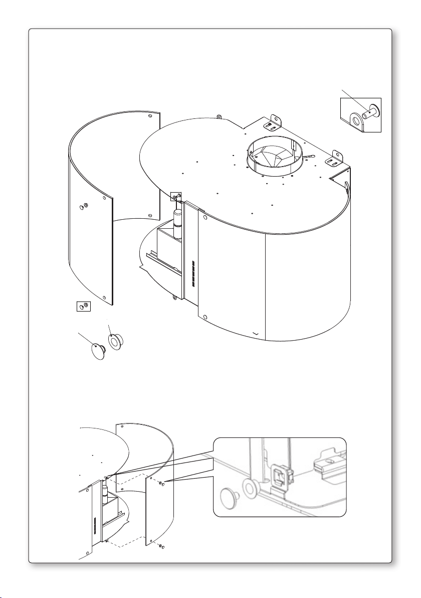
MONTAGGIO CAPPA
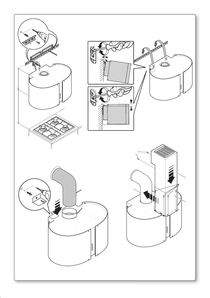
O1 - MONTAGGIO MIRABILIA PARETE
Fase 1
- Appoggiare alla parete la barra di sostegno (A-Fig. O1), ad un’altezza dal pia-
no cottura determinata dalla somma delle quote X+300 mm.
- Controllare con una bolla di livello l’allineamento orizzontale e segnare alle
estremità della barra n° 2 punti di foratura.
- Forare, inserire n° 2 tasselli ad espansione ø 8mm e fissare la barra con le
relative viti.
Fase 2
- Agganciare la cappa alla barra di sostegno (Fig. O2).
- Regolare l’allineamento della cappa tramite le viti delle attaccaglie:
La vite superiore (B) regola la distanza dalla parete, quella inferiore (C) lo
scorrimento verticale.
Fase 3
- Per evitare lo sganciamento della cappa dovuto ad una pressione sottostan-
te, fissarla alla parete con le staffette in dotazione (fig. O3).
- Inserire sul raccordo(D) il tubo (E).
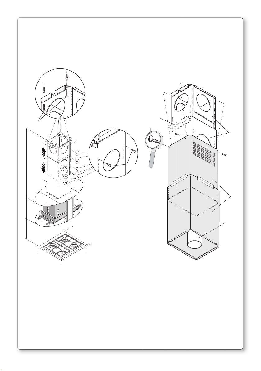
Fase 4
- Infilare nell’elemento (G) la prolunga (H), facendola scorrere fino a raggiun-
gere l’altezza desiderata.
- Trovata la posizione ottimale, fissare la prolunga al camino mediante le viti
(V1) in dotazione;
- Fissare l’assieme camino+prolunga alla cappa mediante le 6 viti V2.
- Eseguire il montaggio dei vetri sulla cappa (fig. O5)
O2 - MONTAGGIO MIRABILIA ISOLA 85/ISOLA 67 CENTRAL
CHIMNEY
Fase 1
- Individuare l’altezza (H1=65) desiderata per il posizionamento della cappa.
- Far scorrere i tralicci (C) e (C1) fino ad ottenere l’altezza desiderata (H2), suc-
cessivamente bloccarli con 8 viti (V2) autofilettanti (Fig.1a).
- Fissare il traliccio (C) al soffitto utilizzando 4 fischer da Ø 8 e relative viti (V1)
(Fig.1b).
Fase 2
- Infilare la prolunga sul camino e bloccarli tra loro con scotch di carta (Fig. 2).
- Fissare l’assieme camino-prolunga (D+E) al traliccio (C) tramite le 4 viti metri-
15
Page 18

che M4 (V3) inserite nei fori esistenti senza bloccarle definitivamente (Fig. 2).
- Nel caso di versione aspirante: individuare l’altezza ottimale del tubo rigido o
flessibile di scarico dei fumi (F) e collegarlo al raccordo motore.
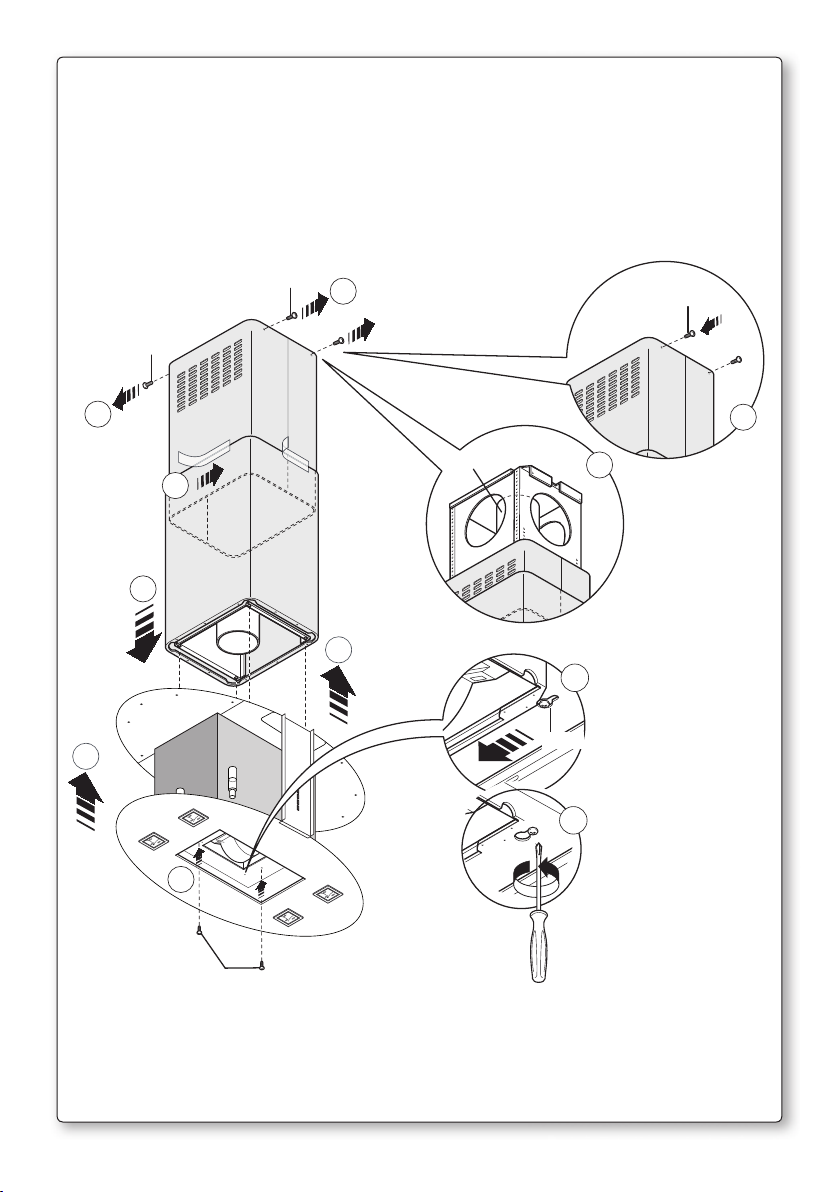
Fase 3
- Alzare la cappa agganciandola alle 4 viti metriche M5 (V4) pre-avvitate al tralic-
cio (C) (centrare i fori Ø11 sull’asola dell’intercamera e traslarla lateralmente)
(Fig. 3a).
- Serrare definitivamente le 4 viti M5 (V4) (Fig. 3b).
- Togliere lo scotch di carta (Fig. 3c), togliere le 4 viti metriche M4 (V3) avvitate
precedentemente sul traliccio (Fig. 3d) e far scorrere verso il basso l’assieme
camino-prolunga (Fig. 3e).
- Eseguire il collegamento del tubo al raccordo del foro di scarico del soffitto
(nel caso di versione aspirante) (Fig. 3f).
- Eseguire il collegamento elettrico solo dopo aver disinserito l’alimentazione
elettrica.
- Fissare la prolunga al traliccio (C) tramite le 4 viti metriche M4 (V3), senza
bloccarle definitivamente (Fig. 3g).
- Bloccare definitivamente la prolunga sul traliccio (C) serrando le 4 viti metri-
che M4 (V3).
- Bloccare il camino tramite 2 viti autofilettanti (V5) (Fig. 3i).
- Utilizzare gli elementi supporto prolunga (A) (Fig. 2) solo nel caso non venga
usato il traliccio superiore, oppure nel caso di un contro-soffitto.
- Eseguire il montaggio dei vetri sulla cappa (fig. O5).
16
Page 19
GB
INSTRUCTIONS BOOKLET
A
WARNINGS
This instruction booklet must be kept together with the appliance for future
reference. If the appliance is sold or consigned to other parties, check that
the booklet is supplied with it, to ensure that the new user has the correct
information on the operation of the range hood and is aware of the warnings.
These warnings have been provided for the your safety and the safety of others. As a result, please read them carefully before installing and operating the
appliance.
This appliance is not intended for use by young children or infirm persons unless they have been adequately supervised by a responsible person to ensure
that they can use the appliance safely. Young children should be supervised to
ensure they do not play with the appliance.
The appliance must be installed by qualified personnel, in accordance with
the standards in force. If the supply cord is damaged, it must be re-placed
by the manufacturer, its service agent or similarly qualified persons in order
to avoid a hazard. Any modifications that may be required to the electrical
system for the installation of the range hood must only be made by qualified
electricians.
It is dangerous to modify or attempt to modify the characteristics of this system. In the event of malfunctions or if repairs are required to the appliance,
do not attempt to solve the problems directly.
Repairs performed by unqualified persons may cause damage. For all repair
and other work on the appliance, contact an authorised service/spare parts
centre.
Always check that all the electrical parts (lights, exhaust device), are off when
the appliance is not being used. Read the entire instruction booklet before
performing any operations on the range hood.
The range hood must only be used for the exhaust of cooking fumes in home
kitchens. The manufacturer disclaims all liability for any other use of the appliance.
The maximum weight of any object placed above the hood, or hung to it (if
possible) must not exceed 1,5 kilos. After installing the stainless steel hood,
clean it in order to remove any residue of the protective glue, and stains of
grease or oil. The manufacturer recommends its cleaning cloth available for
purchase. The manufacturer accepts no liability in case of damage caused by
the use of different detergent types.
B
TECHNICAL SPECIFICATIONS
The technical data pertaining to the electric appliance The technical specifications of the appliance are shown on the rating plates located inside the range
hood.
17
Page 20

C
INSTALLATION
(Section reserved for qualified installers of the range hood)
The distance between the hob and the lowest part of the rangehood is normally
at least 65 cm (see figure C1). This distance is measuresd in the lowest part of
the rangehood not operating at safety voltage. Based on this detail provided by
European Standards, the distance may be reduced in some models as specified
in the general catalogue. If the instructions for installation for the gas hob specify a greater distance, this has to be taken into account.
In the outside exhaust version, the diameter of the fume discharge duct must
be no smaller than the range hood connection.
In the horizontal sections, the duct must slope slightly (around 10%) upwards,
so as to better convey the air outside of the room.
Avoid using angled pipes, make sure that the pipes are at least of the minimum length.
Comply with the current regulations on air discharge into the atmosphere.
If a boiler, stove, fireplace, etc. that uses gas or other fuels is being used at
the same time, make sure the room where the fumes are extracted is well
ventilated, in compliance with the current regulations.
Mounting instruction: see section “O” of the booklet.
D
ELECTRICAL CONNECTIONS
(Section reserved for qualified installers)
WARNING!
Before doing any work inside the range hood, disconnect the appliance from
the mains power supply.
Check that the wires inside the range hood are not disconnected or cut; if this
is the case, contact your nearest service centre. The electrical connections
must be performed by qualified personnel.
The connections must be performed in compliance with the legal standards in
force. Check that the relief valve and the electrical system are able to support
the load of the appliance (see the technical specifications in point B).
Some types of appliance are supplied with a cable without plug; in this case,
“standardised” plugs must be used, keeping in mind that:
- the yellow-green wire must be used for the earth,
- the blue wire must be used for the neutral,
- the brown wire must be used for the phase; the cable must not come into
contact with hot parts (over 70°C).
- fit a plug that is suitable for the load to the power cable, and connect it to a
suitable power outlet.
For appliances that come supplied with cable and plug please ensure they are
plugged into a circuit suitable for this appliance.
Please refer to a qualifed person. (See technical specifications in point B).
The manufacturer declines all liability if the safety standards are not observed.
18
Page 21
E
RANGE HOOD WITH OUTSIDE
DISCHARGE (exhaust)
In this version, the fumes and steam from the kitchen are conveyed outside
through an exhaust duct.
The exhaust conveyor that protrudes from the upper part of the range hood
must be connected to a duct that carries the fumes and steam outside. In this
version, the charcoal filters, if fitted, should be removed; to do this, see the instructions in point F. There must be adequate ventilation of the room when the
range hood is used at the same time as appliances burning gas or other fuels,
according to the standard.
Deviation for Germany:
When the range hood and appliances supplied with energy other than electricity are simultaneously in operation, the negative pressure in the room must
not exceed 4 Pa (4x10 E-5 bar).
F
RECIRCULATING RANGE
HOOD (with filter)
In this version, the air passes through charcoal filters for purification, and is
then recirculated back into the kitchen.
Check that the charcoal filters are fitted to the motor, and if not, install them as
described in the instructions in point H.
If the hood is of filtering type, remove the non-return valve fitted at the motor’s
outlet.
For maximum efficiency, the third speed should be used when there are strong
odours or a lot of steam, the second speed in normal conditions, and the first
speed for keeping the air clean with minimum energy consumption. The range
hood should be switched on when starting to cook, and left on until the odours
disappear.
G
OPERATION
ELECTRONIC CONTROL PANEL
Light pushbutton
- ON: light on (the pushbutton is lit);
- OFF: light off;
Dimmer with keyboard integrated functions: with motor off and prolonged
pressing of keyboard light key (2 seconds), access is gained to the amend
atmosphere light intensity (incandescent or LED lamp). By acting on the +
and – keys, light intensity is adjusted. With motor started, the prolonged
pressing of the key, switches the atmosphere light on or off.
Pushbutton -
Press to reduce motor speed
Speed 1, 2 and 3 are indicated by the number of LEDs that light up (exclud-
ing the light and the timer LEDs).
19
Page 22
Pushbutton +
Press to increase motor speed
Speed 1, 2 and 3 are indicated by the number of LEDs that light up (exclud-
ing the light and the timer LEDs). (In the 4-speed version the pushbutton
+ blinks. The fourth speed remains on for a set duration of time. After 15
minutes the motor returns to the third speed).
Mode pushbutton
Function: it turns hood motor on and off.
The function “desired speed” enables to start the motor at the speed that
was selected before the hood was last turned off.
Optional: version with remote control (some versions only).
WARNING:
Install the hood away from sources of electromagnetic waves, as these
could affect the correct operation of the electronic system.
Maximum operating distance: 5 metres. The maximum operating distance
could be less than 5 metres in case of electromagnetic interference by
other equipment.
Light pushbutton on remote control: light on/off.
– and + pushbutton: increase/decrease speed (to start the motor press
either the + or the – pushbutton).
Timer pushbutton: see instructions below.
Timer and ‘filter clogged’ alarm pushbutton
- This function allows the automatic turning off of the hood after running
for 15 minutes at the speed previously set (the pushbutton shows a flicker-
ing light).
- After about 30 hours of running the pushbutton indicates the need for
washing the metal filters (the pushbutton shows a solid red light). To dis-
able the alarm press the pushbutton for a few seconds until the red light
turns off. Then turn the hood off and on again to check that the alarm has
disappeared.
20
H
FILTERS REMOVING AND REPLACING’S INSTRUCTIONS
1. METAL FILTERS
Open the panel (see fig. H3). Use handle A to remove the metal grease
filter.
A
Page 23
2. CHARCOAL FILTERS
To replace the charcoal filters, proceed as follows: remove the metal filters
as described above. The two filters located at the ends of the motor can now
be easily accessed.
To install the new fi lters see picture.
In case of hood with the motor box the fi lter is located on the botton part of
the motor box.
To install the new fi lters see picture.
To order new charcoal fi lters contact the distributor/retailer.
VALID ONLY FOR ITALY: download the appropriate order form from: www.
falmec.com (access the assistance drop-down menu).
3. REMOVABLE PANEL
Follow the instructions on fig. H3 to remove the panel.
LIGHTING ASSEMBLY AND REPLACEMENT
I
SPOTLIGHT
How to replace a square halogen light:
a) Check that the equipment is disconnected from the power supply.
b) Open the panel completely till 90° (see figure) pressing the PUSH button
c) Replace the lamp with a similar one (halogen, max 20 W, 12 Volt, G4 con-
nection).
d) Close the panel. If the panel does not close correctly repeat the operation
at point b.
Square halogen light
GLASS LIGHTING
To replace the incandescent lamp:
1) ensure the hood is disconnected from the electric mains;
21
Page 24
2) remove the decorative glass (see sec. O);
3) replace the lamp with one of the same model (max. 25W);
4) re-mount the glass (see fig. O5).
In case of hoods with LED lighting, the replacement of the luminous body can
only be carried out by specialised staff and with original spare parts.
WARNING: Do not remove the glass if the glass LED lighting is on.
L
Constant maintenance ensures the correct operation and efficiency of the ap-
MAINTENANCE AND CLEANING
pliance over time. Special attention should be paid to the metal grease-trapping filters and the charcoal filters. Frequent cleaning of the filters and their
supports will ensure that fats and grease do not accumulate on the range
hood, with the consequent risk of fire.
1. METAL GREASE-TRAPPING FILTERS
These trap the fat and grease particles suspended in the air, and therefore
should be washed every month in hot water and detergent, without bend-
ing them. Wait until they are completely dry before repositioning them.
To remove and replace these filters, see the instructions in point H1. This
operation should be performed at regular intervals.
2. CHARCOAL FILTERS
These trap the odours present in the stream of air that passes through
them. The air is purified by passing a number of times through the filters
and being recirculated into the kitchen. The charcoal filters cannot be
cleaned, and should be replaced on average every 3-4 months (according
to use). To replace the charcoal filters, see the instructions in point H2.
3. CLEANING THE OUTSIDE OF THE APPLIANCE
It is advised to clean the external hood surfaces at least every 15 days in
order to avoid that oily or greasy substances affect the steel surfaces.
The ouside of the range hhod should be cleaned using a damp cloth and
neutral liquid detergent or denatured alcohol.
In case of fingerprint-less finish (fasteel) clean only with water and neutral
soap using clean with a soft cloth, rinse and wipe dry thoroughly. Do not use
products that contain abrasive substances, rough cloths or cloths specifically
designed for cleaning steel. Using abrasive substances or rough cloths will
inevitably damage the finish of steel. The steel surface will be irrevocably
damaged if the instructions above are not complied with.
Keep these instructions together with the instructions for use of your hood.
The manufacturer accepts no liability for any damage caused by non-compli-
ance with the instructions above.
4. CLEANING THE INSIDE OF THE APPLIANCE
The electrical parts or parts of the motor assembly inside the range hood
must not be cleaned using liquids or solvents.
Do not use abrasive products. All the above operations must be performed
after having disconnected the appliance from the mains power supply.
22
Page 25

M
Do not connect the appliance to flues (from boilers, fireplaces, etc.). Make sure
Never cook on “open” flames under the range hood.
Check deep-fryers during use: superheated oil may be flammable.
SAFETY WARNINGS
The electrical system features an earth connection in compliance with interna-
tional safety standards; furthermore, it is compliant with the European standard
for electromagnetic compatibility.
the mains voltage corresponds to the values on the rating plate located inside
the range hood. The minimum safety distance between the cooktop and the
range hood must be at least 65 cm.
- Ensure there is adequate ventilation of the room when the rangehood is used
at the same time as appliances burning gas or other fuels.
- Do not flambe under the rangehood
- The exhaust air must not be discharged into a flue which is used for exhaust-
ing fumes from appliances burning gas or other fuels.
- Ensure that all regulations concerning the discharge of exhaust air have been
fulfilled before you use the appliance.
Before performing any cleaning or maintenance operations, disconnect the ap-
pliance by unplugging it or using the main switch. The manufacturer disclaims
all liability for any damage that may be directly or indirectly caused to people,
things and animals due to the failure to follow all the instructions provided in
this booklet and above all the warnings relating to the installation, operation
and maintenance of the appliance.
N
The new equipment is covered by warranty.
The warranty conditions are provided by the distributor.
O
WARRANTY
The manufacturer is not liable for any inaccuracies in this booklet resulting
from printing or transcription errors. The manufacturer reserves the right to
modify its products as it considers necessary or in the interests of the user,
without compromising their essential safety and operating characteristics.
HOOD INSTALLATION
O1 - INSTRUCTIONS FOR WALL-MOUNTED MIRABILIA HOODS
Phase 1
- Place the support bar next to the wall (A-Fig. O1), at a height above the cook-
top which corresponds to X+300 mm.
- With a spirit level check that the bar is horizontal. Mark a point at each end
of the bar.
- Drill the holes, fit 2 ø8mm expansion joints and screw in the bar.
Phase 2
- Fit the hood to the support bar (Fig. O2).
- Adjust hood alignment with the relevant screws: The top screw (B) adjusts
the distance from the wall. The bottom screw (C) adjusts the vertical sliding
movement.
23
Page 26

Phase 3
- To prevent the hood from detaching if pressure is exerted from beneath,
secure it to the wall with the brackets supplied (fig. O3).
- Fit pipe/hose (E) into (D).
Phase 4
- Slide the extension (H) into (G) till the desired height.
- When the extension is at the desired height, screw it onto the chimney with
the screws supplied (V1);
- Lock the chimney + extension onto the hood with 6 V2 screws.
- Fit the glass panels (fig. O5).
O2 - INSTRUCTIONS FOR MIRABILIA ISLAND 85/ISLAND 67
CENTRAL CHIMNEY
Phase 1
- Identify the desired height (H1=65) for the positioning of the hood.
- Slide the lattice-works (C) and (C1) to the desired height (H2), then block
them with the 8 self-threading screws (V2) (Fig.1a).
- Fasten the lattice-work (C) to the ceiling using the four Ø 8 expansion plugs
and relative screws(V1) (Fig.1b).
Phase 2
- Insert the extension on the flue and fasten them to each other with masking
tape (Fig. 2).
- Fasten the flue-extension assembly (D+E) to the lattice-work (C) with the 4
M4 metric screws (V3) inserted in the existing holes without tightening them
completely (Fig. 2).
- For suction version: identify the optimal height for the rigid or flexible ex-
haust pipe (F) and connect it to the motor connection.
Phase 3
- Raise the hood, hooking it onto the 4 M5 metric screws (V4) pre-tightened
to the lattice-work (C) (center the Ø11 holes on the slot of the inner liner and
move it laterally)(Fig. 3a).
- Completely tighten the 4 M5 screws (V4) (Fig. 3b).
- Remove the masking tape (Fig. 3c), remove the four M4 metric screws (V3)
previously tightened onto the lattice-work (Fig. 3d) and slide the flue-extension assembly downwards. (Fig. 3e).
- Connect the pipe to the connection of the ceiling discharge hole. (Fig. 3f).
- Make electrical connections only after having removed electrical power sup-
ply.
- Fasten the extension to the lattice-work (C) by means of the 4 M4 metric
screws (V3), without tightening them completely(Fig. 3g).
- Block the extension completely to the lattice-work (C) by screwing down the
4 M4 metric screws (V3).
- Block the flue with the 2 self-threading screws (V5) (Fig. 3i).
- Use the extension support elements(A) (Fig. 2) only if the upper lattice-work
is not used, or in the case of a false ceiling.
- Fit the glass panels (fig. O5).
24
Page 27

D
BEDIENUNGSANLEITUNG
A
Sollte das Gerät verkauft bzw. einer anderen Person übergeben werden, muss
Diese Hinweise sind für Ihre Sicherheit und die anderer Personen abgefasst
HINWEISE
Diese Bedienungsanleitung muss unbedingt zusammen mit dem Gerät auf-
bewahrt werden, um in Zukunft nachgeschlagen werden zu können.
die Bedienungsanleitung unbedingt mitgeliefert werden, damit der neue Benutzer mit dem Betrieb der Dunstabzugshaube und den diesbezüglichen Hinweisen vertraut werden kann.
worden. Daher sollten Sie die Bedienungsanleitung vor der Installation und
Verwendung des Gerätes aufmerksam durchlesen.
Das Gerät darf nicht von Kindern bzw. Behinderten benutzt werden, es sei denn
diese werden von verantwortungsvollen Personen, die dafür Sorge tragen,
dass das Gerät sicher verwendet wird, überwacht.
Kinder müssen von einer von verantwortungsvollen Person überwacht werden,
damit sie nicht mit dem Gerät spielen.
Die Installation hat den geltenden Vorschriften gemäß von kompetenten, qualifizierten Installateuren durchgeführt zu werden.
Beschädigte Speisekabel sind vom Hersteller bzw. von dessen Kundenservice
bzw. von einer Person mit ähnlicher Qualifikation auszuwechseln, um Gefahren
vorzubeugen.
Eventuelle erforderliche Änderungen, die für die Installation der Dunstabzugshaube an der elektrischen Anlage durchgeführt werden müssen, dürfen
ausschließlich von kompetenten Personen vorgenommen werden.
Es ist gefährlich, die Eigenschaften dieser Anlage abzuändern bzw. versuchen
abzuändern. Bei Reparaturen bzw. Betriebsstörungen des Gerätes nicht versuchen, das Problem alleine zu lösen.
Die Reparaturen, die von nicht kompetenten Personen durchgeführt werden,
können Schäden verursachen.
Sich für eventuelle Eingriffe an einen zugelassenen Kundenservice, der über die
geeigneten Ersatzteile verfügt, wenden.
Wenn das Gerät nicht benutzt wird, müssen alle elektrischen Teile (Beleuchtung,
Absaugvorrichtung) ausgeschaltet sein. Vor Durchführung von Arbeitsvorgängen an der Dunstabzugshaube die Bedienungsanleitung lesen.
Die Dunstabzugshaube darf ausschließlich zum Absaugen des Dampfes, der
beim Kochen in einer Haushaltsküche entsteht, verwendet werden.
Bei anderen Einsätzen wird der Hersteller von jeder Haftung befreit.
Das Gesamtgewicht von Gegenständen, die eventuell auf die Dunstabzugshaube positioniert bzw. an diese gehängt werden (falls vorgesehen), darf höchstens 1,5 Kg betragen.
Nach der Installation von Edelstahlhauben muss man diese reinigen, um Schutzkleberreste und eventuelle Fett- und Ölflecken zu entfernen.
Der Hersteller empfiehlt für doesen Arbeitsvorgang die Verwendung der mitgelieferten Reinigungstücher.
Die Verwendung anderer Reinigungsmittel befreit den Hersteller von jeder Haftung für eventuelle auf deren Benutzung zurückzuführende Schäden.
25
Page 28

B
TECHNISCHE MERKMALE
Die technischen Daten des Elektrogeräts sind an den Typenschildern im Innern
der Dunstabzugshaube angegeben.
C
D
INSTALLATION
(Dieser Abschnitt ist Fachpersonal mit der für die Montage der Dunstabzugshaube erforderlichen Qualifikation vorbehalten)
Der Abstand zwischen Kochebene und dem unteren Teil der Abzugshaube
muss normalerweise mindestens 65 cm betragen (siehe Abbildung C1). Dieser
Abstand muss unbedingt am untersten Punkt der Haube ohne Sicherheitsspannung gemessen werden. Ausgehend von diesem von den Europäischen
Normen vorgesehenem Detail kann man den Abstand an einigen Modellen
reduzieren, wie es im Hauptkatalog spezifiziert wird. Wenn die Anweisungen
der Gaskochebene einen größeren Abstand vorsehen, muss dies berücksichtigt
werden.
In der Abluftversion kann der Durchmesser des Rauchablasses nicht kleiner als
der des Dunstabzugshaubenanschlusses sein.
In den waagrechten Abschnitten muss das Rohr leicht nach oben geneigt sein
(ca. 10%), um die Luft nach außen zu leiten.
Die Kurven auf ein Minimum reduzieren und prüfen, ob alle Rohre die erforderliche Mindestlänge aufweisen.
Die geltenden Vorschriften bezüglich des Luftablasses nach draußen beachten.
Bei gleichzeitiger Verwendung anderer mit Gas oder anderen Brennstoffen gespeister Verbraucher (Heizkessel, Öfen, Kamine, usw...) für eine angemessene,
vorschriftsmäßige Lüftung des Raumes, in dem die Rauchabsaugung erfolgt,
sorgen.
Montageanleitungen: siehe Abschnitt “O” der vorliegenden Bedienungsanleitung.
ELEKTRISCHER ANSCHLUSS
26
(Dieser Abschnitt ist Fachpersonal mit der für den Stromanschluss erforderlichen Qualifikation vorbehalten)
ACHTUNG!
Vor jedem Eingriff im Innern der Haube muss das Gerät vom Stromnetz
getrennt werden. Sicherstellen, dass die Stromkabel im Innern der Dunstabzugshaube nicht abgeklemmt oder durchgeschnitten werden; sollte dies
dennoch vorkommen, den nächst gelegenen Kundendienst kontaktieren.
Der Anschluss muss unter Befolgung der gültigen Rechtsvorschriften erfolgen. Sicherstellen, dass das Reduzierventil und die Elektroanlage der
Geräteleistung entsprechen (siehe technische Spezifikationen in Punkt B).
Einige Gerätetypen können mit einem Kabel ohne Stecker ausgestattet sein,
in diesem Fall ist ein “genormter“ Stecker zu verwenden, wobei folgendes zu
beachten ist:
- Der gelb/grüne Draht ist für die Erdung zu benutzen;
Page 29

- der blaue Draht ist für den Nullleiter, und
- der braune Draht für die Phase bestimmt. Das Kabel darf auf keinen Fall mit
heißen Teilen in Berührung kommen (über 70°C).
- Am Netzkabel einen der Geräteleistung entsprechenden Stecker anbringen
und diesen in eine Sicherheits- Steckdose stecken.
Bei Geräten, die mit Kabel und Stecker ausgestattet geliefert werden, muss
man sicherstellen, dass sie mit einem geeigneten Kreislauf verbunden werden. Sich an eine qualifizierte Person wenden (siehe technische Spezifikationen in Punkt B).
Die Herstellerfirma ist nicht haftbar, wenn die Unfallverhütungsvorschriften
nicht eingehalten werden.
E
HAUBE MIT ABLUFTBETRIEB
(absaugend)
Bei dieser Ausführung wird der während des Kochens entstehende Dampf
durch ein Abzugsrohr nach außen abgeführt.
Der sich oberhalb der Haube befindliche Rauchzug ist an ein Abzugsrohr anzuschließen, über das Rauch und Dampf zu einem Auslass ins Freie geleitet
werden. Bei dieser Ausführung sind eventuell vorhandene Aktivkohlefilter wie
in Punkt F beschrieben zu entfernen. Wenn die Dunstabzugshaube gleichzeitig
mit anderen Geräten benutzt wird, die mit Gas oder anderen Brennstoffen
betrieben werden, muss eine ausreichende Belüftung des Raums gesorgt
werden.
Germany (Feuerungsverordnung vom 31-01-1986 und DVGW-TRGI 1986,
Amtsblatt G 600):
Bei gleichzeitigem Betrieb der Dunstabzugshau-be im Abluftbetrieb und
Feuerstätten darf im Aufstellraum der Feuerstätte der Unterdruck nicht
größer als 4 Pa (4 x 10⁻⁵ bar) sein.
F
HAUBE MIT UMLUFTBETRIEB
(filtrierend)
Bei dieser Ausführung strömt die Luft durch Aktivkohlefilter, wo sie gefiltert
und erneut an den Raum abgegeben wird. Sicherstellen, dass die Aktivkohlefilter am Motor installiert sind, andernfalls müssen sie wie unter Punkt H
beschrieben installiert werden.
Bei Dunstabzugshauben im Umluftbetrieb empfehlen wir die Rückstauklappe,
die am Ausgangsverbindungsstück des Motors montiert ist, zu entfernen.
Für optimale Leistung ist es ratsam, bei starker Geruch- und Dampfbildung
die dritte Drehzahlstufe, und unter normalen Bedingungen die zweite Stufe einzustellen. Die erste Drehzahlstufe dient dazu, die Luft bei geringem
Energieverbrauch sauber zu halten. Die Haube sollte bei Kochbeginn eingeschaltet, und erst wieder ausgeschaltet werden, wenn der Raum vollkommen
geruchsfrei ist.
27
Page 30

G
ARBEITSWEISE
ELEKTRONISCHES BEDIENFELD
Lichtknopf
• ON: Licht eingeschaltet (Druckknopf beleuchtet);
• OFF: Licht ausgeschaltet.
Dimmer mit in der Tastatur integrierten Funktionen: bei ausgeschaltetem
Motor kann man durch langes Drücken der Taste Licht (2 Sekunden) an der
Tastatur auf die Modalität Änderung der Intensität des Umgebungslichtes
(Glühlampe oder Led) zugehen. Wirkt man auf die Tasten + und – ein, kann
die Lichtintensität eingestellt werden. Bei eingeschaltetem Motor wird
durch langes Drücken der Taste das Umgebunglicht ein- bzw. ausgeschaltet.
Druckknopf -
Bei Betätigung dieses Druckknopfes wird die Motorgeschwindigkeit redu-
ziert. Die Geschwindigkeit 1,2 und 3 wird von der eingeschalteten Ledanzahl ausschließlich Licht- und Schaltuhrled angezeigt.
Druckknopf +
Bei Betätigung dieses Druckknopfes wird die Motorgeschwindigkeit ge-
steigert.
Die Geschwindigkeit 1,2 und 3 wird von der eingeschalteten Ledanzahl
ausschließlich Licht- und Schaltuhrled angezeigt.
(In der Ausführung mit 4 Geschwindigkeiten zeichnet sich die Taste + dur-
ch ein Blinklicht aus. Die 4. Geschwindigkeit (Intensivgeschwindigkeit) ist
zeitgesteuert und nach ca. 15 Minuten geht der Motor automatisch zur 3.
Geschwindigkeit über).
Modalität- Druckknopf
Funktion: Ein- und Ausschaltung des Abzugshaubenmotors.
Die Funktion “gewünschte Geschwindigkeit” gestattet die Einschaltung
des Motors bei der Geschwindigkeit, die vor der letzten Ausschaltung
gewählt worden war.
Option: Ausführung mit Fernbedienung (nur für einige Ausführungen
erhältlich).
HIN WEISE:
Das Gerät nicht in der Nähe von elektromagnetischen Wärmequellen po-
sitionieren, da diese die Funktion der Elektronik der Dunstabzugshaube
beeinträchtigen könnten.
Maximaler Betriebsabstand 5 Meter. Dieser Abstand kann bei elektroma-
gnetischen Interferenzen anderer Geräte kürzer sein.
Lichtknopf der Fernbedienung: On/Off Licht.
Druckknopf – und + Reduzierung/Steigerung der Geschwindigkeit (zur Mo-
toreinschaltung ist es gleichgültig, ob man auf die Taste + oder - drückt.
Schaltuhrknopf: siehe nachstehende Anleitungen.
28
Druckknopf Schaltuhr und Filterverstopfung
• Diese Funktion gestattet die automatische Ausschaltung der Dunsta-
Page 31

bzugshaube nach einem Betrieb von 15 Minuten bei der zuvor eingestell-
ten Geschwindigkeit (Druckknopf mit Blinklicht).
• Nach 30 Betriebsstunden zeigt der Druckknopf an, daß eine Spülung der
Metallfilter erforderlich ist (Druckknopf rot beleuchtet). Anschließend die
Dunstabzugshaube ausschalten undwieder einschalten, um zu prüfen, ob
der Alarm aufgehoben wurde.
H
ANLEITUNGEN FÜR AUSBAU
UND ERSATZ
1. METALLFILTER
Das Paneel öffnen (siehe Abb. H3). Um den Metallfettfilter zu entfernen,
den Griff A betätigen.
A
2. AKTIVKOHLEFILTER
Um die Aktivkohlefilter auszuwechseln, wie folgt vorgehen: die Metallfil-
ter, wie zuvor erklärt, entfernen. Auf diese Weise kann man die zwei Filter,
die an der rechten und linken Seite des Leitblechs befestigt sind, leicht
erreichen.
Für die Montage/das Auswechseln siehe Abb.
Im Falle von Dunstabzugshauben mit Motorkammer befindet sich der Fil-
ter im unteren Kammerteil. Für die Montage/das Auswechseln siehe Abb.
Zur Bestellung neuer Karbonfilter bitte an die Vertragshandlung/Vertrieb-
sunternehmen.
NUR FÜR ITALIEN: Entsprechendes Formular von der Internetseite: www.
falmec.com herunterladen (Zugriff über Pull-down-Menü).
29
Page 32

3. ABSETZBARE TAFEL
Folgen Sie den Anweisungen auf Abb. H3, um die Tafel zu entfernen.
BELEUCHTUNG MONTAGE UND ERSATZ
I
LAMPE
Auswechseln der Lampe “Square halogen light”:
a) Sich vergewissern, dass das Gerät nicht an das Stromnetz angeschlossen
ist.
b) Die Platte vollständig bis zu einem Winkel von 90° öffnen (siehe Abbildung),
indem man auf PUSH drückt.
c) Die Lampe mit einer Lampe desselben Typs auswechseln (Halogenlampe
max. 20 W, 12 Volt Anschluss G4).
d) Die Platte wieder schließen. Wenn sich die Platte nicht korrekt schließen lässt,
den in Punkt b) beschriebenen Vorgang wiederholen.
Square halogen light
BELEUCHTUNG DER SICHTFENSTER
Auswechseln der Glühlampe:
Im Falle von Abzughauben mit Led-Beleuchtung, darf das Auswechseln des
HINWEIS: Die Glasscheiben nicht entfernen, wenn die Led-Beleuchtung der
1) sicherstellen, dass die Abzughaube vom Stromnetz abgetrennt ist;
2) das Ornamentglas entfernen (siehe Abschnitt O);
3) die Lampe mit einer gleichwertigen auswechseln (max. 25W);
4) die Glasscheiben erneut montieren (siehe Abb. O5).
Leuchtkörpers nur von spezialisiertem Personal und durch Originalersatzteile
erfolgen.
Scheiben eingeschaltet ist.
L
Nur durch eine konstante Wartung ist ein einwandfreier Betrieb und eine lan-
WARTUNG UND REINIGUNG
ge Lebensdauer der Dunstabzugshaube gewährleistet. Besondere Aufmerksamkeit ist den Metall-Fettfiltern und den Aktivkohlefiltern zu schenken. Eine
häufige Reinigung der Filter und deren Halter gewährleistet, dass sich an der
Dunstabzugshaube keine feuergefährlichen Fettansammlungen bilden.
1. METALL-FETTFILTER
Diese Filter haben die Aufgabe, die schwebenden Fettteilchen zurückzuhal-
ten, sie sollten daher jeden Monat mit warmem Wasser. Gereinigt werden,
wobei darauf zu achten ist, dass sie nicht geknickt werden. Für den Aus- und
30
Page 33

Einbau wird auf die Anleitungen unter Punkt H1 verwiesen. Die Reinigung
muss unbedingt regelmäßig durchgeführt werden.
2. AKTIVKOHLEFILTER
Diese Filter haben die Aufgabe, die in der Luft, die sie durchströmt, enthal-
tenen Gerüche zurückzuhalten. Die durch mehrmaliges Durchströmen der
Filter gereinigte Luft wird wieder in die Küche zurückgeführt.
Die Aktivkohlefilter können nicht gewaschen werden und müssen durchsch-
nittlich alle 3-4 Monate ersetzt werden (die Häufigkeit hängt vom Gebrauch
ab). Für den Ersatz der Aktivkohlefilter wird auf die Anleitungen unter Punkt
F verwiesen.
3. AUSSENREINIGUNG
Wir empfehlen, die äußeren Oberflächen der Hauben mindestens alle 15 Ta-
ge zu reinigen, um zu vermeiden, dass die öligen oder fettigen Substanzen
die Oberflächen aus Stahl angreifen.
Die Reinigung der Dunstabzugshaube wird mit einem feuchten Schwamm
und einem neutralen Flüssigreiniger bzw. denaturiertem Alkohol durchge-
führt. Bei Material, dass einer Fingerabdruckschutzbehandlung (Fasteel)
unterzogen wurde, die Reinigung nur mit Wasser und einer neutralen Seife
vornehmen; hierfür ein weiches Tuch verwenden, gründlich abspülen und
trocknen. Es dürfen keine Produkte, die Scheuermittel enthalten, Tücher mit
rauher Oberfläche bzw. handelsübliche Tücher für die Stahlreinigung ver-
wendet werden. Die Verwendung von Scheuermitteln und rauhen Tüchern
wird die Oberflächenbehandlung des Stahls für immer beschädigen.
Bei Nichtbeachtung dieser Hinweise wird es zu einer nicht mehr zu beseiti-
genden Beschädigung der Stahlfläche kommen.
Die vorliegenden Hinweise müssen zusammen mit der Bedienungsanlei-
tung der Dunstabzugshaube aufbewahrt werden.
Der Hersteller lehnt bei Nichtbeachtung dieser Anweisungen jede Haftung
ab.
4. REINIGUNG DER INNENFLÄCHE
Die elektrischen Teile oder Teile des Motors im Innern der Dunstabzugshau-
be dürfen nicht mit Flüssigkeiten oder Lösemittel gereinigt werden.
Keine Schleifmittel benutzen.
Vor der Reinigung muss das Gerät vom Stromnetz getrennt werden.
M
Das Gerät auf keinen Fall an die Ablassleitungen von Rauch, das durch Ver-
Der Mindestsicherheitsabstand zwischen Kochebene und Dunstabzugshaube
Auf keinen Fall unter der Dunstabzugshaube auf “offenem Feuer” kochen. Die
SICHERHEITSBESTIMMUNGEN
Die elektrische Anlage ist mit einer Erdung ausgestattet, die den internationa-
len Sicherheitsvorschriften entspricht; sie erfüllt außerdem die europäischen
Entstörungsvorschriften.
brennung entsteht (Heizkessel, Kamine, usw...), anschließen. Sich vergewissern, dass die Netzspannung mit den im Inneren der Dunstabzugshaube
angegebenen Daten übereinstimmt.
muss mindestens 65 cm betragen.
Friteusen während der Benutzung kontrollieren: das überhitzte Öl könnte sich
31
Page 34

entzünden.
Für eine ausreichende Lüftung im Raum sorgen, wenn die Dunstabzugshaube
zusammen mit anderen Geräten, die mit Brennstoffen und ähnlichen Stoffen
arbeiten, verwendet wird.
- Kein offenes Feuer unter der Haube anzünden.
- Das Gerät auf keinen Fall an die Ablassleitungen von Rauch, das durch Verbrennung entsteht (Heizkessel, Kamine, usw...), anschließen.
- Sich vergewissern, dass alle gelten Vorschriften bezüglich der Luftablasses
außerhalb des Raumes erfüllt werden, bevor man die Dunstabzugshaube benutzt.
Vor Durchführung von Reinigungs- oder Wartungsarbeiten muss man die
Stromversorgung unterbrechen, indem man den Stecker zieht bzw. den
Hauptschalter betätigt. Der Hersteller lehnt jede Haftung für eventuelle direkte oder indirekte Schäden an Personen, Gegenständen und Haustieren
ab, die auf die Nichteinhaltung der in der vorliegenden Bedienungsanleitung
enthaltenen Vorschriften zurückzuführen sind und insbesondere die Installation, Bedienung und Wartung des Gerätes betreffen.
N
Was die garantie betrifft, wenden sie sich am austräger.
O
GARANTIE
Die Herstellerfirma haftet nicht für mögliche Ungenauigkeiten infolge Druck-
oder Schreibfehler in diesem Anleitungsheft. Sie behält sich außerdem das
Recht vor, an ihren Produkten sämtliche Änderungen vorzunehmen, die sie
auch im Interesse des Benutzers für erforderlich oder nützlich erachtet, ohne
die wesentlichen Merkmale in Bezug auf Funktionalität und Sicherheit zu
beeinträchtigen.
MONTAGE DER INSEL-DUNSTABZUGSHAUBE
O1 - MONTAGE MIRABILIA WANDAUSFÜHRUNG
Schritt 1
- Die Stützstange (A-Abb. O1) an der Wand positionieren. Hierbei eine Höhe
von der Kochplatte wählen, die durch die Summe der Maße X+300 mm
berechnet wird.
- Die waagrechte Ausrichtung mit einer Wasserwaage prüfen und 2 Bohrpunkte
an den Stangenenden markieren.
- Bohren, 2 Expansionsdübel ø 8mm einfügen und die Stange mit den
entsprechenden Schrauben einfügen.
Schritt 2
- Die Dunstabzugshaube an die Stützstange anhängen (Abb. O2).
- Die Ausrichtung der Dunstabzugshaube mit Hilfe der Schrauben regeln:
die obere Schraube (B) dient zur Einstellung des Abstands von der Wand und
die untere Schraube (C) des senkrechten Gleitvorgangs.
Schritt 3
- Um zu verhindern, dass sich die Haube durch den von unten kommenden
32
Page 35

Druck löst, muss sie mit Hilfe der mitgelieferten Bügel an der Wand befestigt
werden (Abb. O3).
- Das Rohr (E) in das Anschlussstück (D) einfügen.
Schritt 4
- Die Verlängerung (H) in das Element (G) schieben, indem man diese bis zum
Erreichen der gewünschten Höhe gleiten lässt.
- Sobald man die optimale Position gefunden hat, die Verlängerung mit Hilfe
der mitgelieferten Schrauben (V1) an den Kamin befestigen;
- Die Einheit Kamin+Verlängerung mit den 6 Schrauben V2 an die
Dunstabzugshaube befestigen.
- Die Glasscheiben an der Dunstabzugshaube anmontieren (Abb. O5).
O2 - MONTAGE MIRABILIA ISOLA 85/ISOLA 67 CENTRAL
CHIMNEY
Schritt 1
- Die gewünschte Höhe (H1=65) für die Anbringung der Abzugshaube
festlegen.
- Die Hängegerüste (C) und (C1) auf die gewünschte Höhe bringen (H2) und
mit 8 gewindeformenden Schrauben (V2) befestigen (Abb.1a).
- Das Hängegerüst (C) mit 4 Fischerdübeln Ø 8 mm und den jeweiligen
Schrauben (V1) an der Decke anbringen (Abb.1b).
Schritt 2
- Das Verlängerungsstück in den Kamin einschieben und die beiden Teile mit
Papierklebeband aneinander befestigen (Abb. 2).
- Die Einheit Kamin-Verlängerungsstück (D+E) mit den 4, in die bereits vorhan-
denen Bohrlöcher eingesetzten metrischen Schrauben M4 (V3) am Hängegerüst (C) befestigen, ohne die Schrauben ganz festzuziehen (Abb. 2).
- Bei der Version mit Abluftbetrieb: die optimale Höhe des festen oder bieg-
samen Rauchabzugsrohrs (F) festlegen und mit der Motoranschlussöffnung
verbinden.
Schritt 3
- Die Dunstabzugshaube anheben und in die 4 bereits am Hängegerüst
(C) angebrachten metrischen Schrauben M5 (V4) einhängen (dazu die
Bohrlöcher Ø11 am Knopfschlitz des Zwischenraums gerade ausrichten und
die Abzugshaube seitlich verschieben) (Abb. 3a).
- Nun die 4 Schrauben M5 (V4) endgültig festziehen (Abb. 3b).
- Das Papierklebeband entfernen (Abb. 3c), die 4 vorher am Hängegerüst
angebrachten metrischen Schrauben M4 (V3) entfernen (Abb.3d) und die
Einheit Kamin-Verlängerungsstück nach unten gleiten lassen (Abb.3e).
- Den Anschluss des Rohrs am Anschluss der Abzugsöffnung in der Decke
durchführen (bei Version mit Abluftbetrieb) (Abb. 3f).
- Die Stromversorgung unterbrechen und den Elektroanschluss durchführen.
- Das Verlängerungsstück mit den 4 metrischen Schrauben M4 (V3) am Hän-
gegerüst (C) befestigen, ohne die Schrauben ganz festzuziehen (Abb. 3g).
- Das Verlängerungsstück durch das Festziehen der Schrauben M4 (V3) end-
gültig am Hängegerüst (C) blockieren.
- Den Kamin mit 2 gewindeformenden Schrauben (V5) befestigen (Fig. 3i).
- Die beiden Stützelemente des Verlängerungsstücks (A) (Abb. 2) nur dann
33
Page 36

verwenden, wenn kein oberes Hängegerüst eingesetzt wird oder wenn eine
Zwischendecke vorhanden ist. Die Glasscheiben an die Dunstabzugshaube
anmontieren (Abb. O5).
34
Page 37

F
LIVRET D’INSTRUCTIONS
A
Si l’appareil est vendu ou cédé à tiers, veiller à ce que la notice soit fournie en
La notice a été rédigée pour votre sécurité et celle d’autrui. Nous vous prions
AVERTISSEMENTS
Conserver cette notice avec l’appareil pour pouvoir la consulter en cas de
besoin.
même temps pour que le nouvel utilisateur puisse avoir toutes les indications
concernant le fonctionnement de la hotte et les avertissements correspondants.
donc de la lire attentivement avant de monter et d’utiliser l’appareil.
Les enfants ou les handicapés ne doivent se servir de l’appareil que sous la
surveillance d’une personne responsable pouvant s’assurer qu’ils l’utilisent
en toute sécurité.
Veiller à ce que les enfants ne jouent pas avec l’appareil.
L’appareil doit être monté par un installateur compétent et qualifié, conformément aux normes en vigueur.
Si le câble d’alimentation est abîmé, demander au fabricant, à un Service
après-vente agréé ou à une personne expérimentée de le remplacer afin de
prévenir tout risque de danger.
Les modifications éventuelles de l’installation électrique, qui s’avèrent nécessaires pour monter la hotte, doivent être faites par du personnel compétent.
Il est dangereux de modifier ou d’essayer de modifier les caractéristiques de
cette installation. En cas de panne ou de mauvais fonctionnement de l’appareil, ne pas essayer de résoudre le problème mais s’adresser au Service
après-vente agréé.
Les réparations faites par des personnes non compétentes peuvent abîmer
l’appareil.
Pour toute intervention, s’adresser à un Service après-vente agréé en mesure
de fournir les pièces détachées.
Toujours vérifier si les parties électriques, (lumières, aspirateur) sont éteintes
quand l’appareil n’est pas utilisé. Lire entièrement la notice avant d’effectuer
une opération quelconque sur la hotte.
La hotte s’utilise de la même façon que les aspirateurs des fumées de cuisson
au-dessus des cuisinières domestiques.
Le fabricant décline toute responsabilité en cas d’usage impropre.
Le poids maximal des objets éventuels placés ou suspendus (quand c’est
prévu) sur la hotte ne doit pas dépasser 1,5 kg.
Après avoir monté la hotte en acier inox, la nettoyer pour éliminer les résidus
de colle ou de produit de protection et les taches de graisse ou d’huile.
Pour exécuter cette opération, le constructeur recommande l’utilisation des
lingettes détergentes fournies avec la lampe.
Le fabricant décline toute responsabilité pour les dommages éventuels en cas
d’emploi d’autres types de détergents.
35
Page 38

B
CARACTÉRISTIQUES TECHNIQUES
Les données techniques de l’appareil sont reportées sur les plaques qui se
trouvent à l’intérieur de la hotte (enlever les grilles métalliques pour voir
l’étiquette.
C
D
MONTAGE
(partie réservée au personnel qualifié pour le montage de la hotte)
La distance entre la cuisinière et la partie la plus basse de la hotte de cuisine est,
selon la norme, d’au moins 65 cm (voir figure C1). Cette distance est mesurée
précisément sur le point le plus bas de la hotte avec contrainte qui ne représente pas une contrainte admissible. En se basant sur ce détail prévu par les
normes européennes, il est possible de réduire la distance sur certains modèles,
comme indiqué dans le catalogue général. Si les instructions de la cuisinière à
gaz indiquent une distance plus grande, il faut en tenir compte.
Dans la version aspirante, le tuyau de sortie des fumées doit avoir un diamètre
non inférieur à celui du raccord de la hotte.
Le tuyau doit être légèrement incliné (environ 10%) vers le haut dans la partie
à l’horizontale pour acheminer l’air à l’extérieur du local.
Réduire le plus possible les coudes, vérifier si les tuyaux ont la longueur minimale indispensable.
Respecter les normes en vigueur sur l’évacuation de l’air à l’extérieur.
Si la hotte fonctionne en même temps que d’autres appareils alimentés au gaz
ou avec d’autres combustibles (chaudières, poêles, cheminées, etc.), s’assurer
que le local où a lieu l’aspiration des fumées est bien aéré, conformément aux
normes en vigueur.
Instructions de montage: voir section «O» de la présente notice.
BRANCHEMENT ÉLECTRIQUE
(partie réservée au personnel qualifié pour le branchement)
ATTENTION!
Toujours débrancher l’appareil avant de faire une opération quelconque à
l’intérieur de la hotte.
S’assurer qu’aucun fil n’est débranché ou coupé ; si c’est le cas, contacter le
Service après-vente le plus proche.
S’adresser à du personnel qualifié pour le branchement électrique.
Les branchements doivent être effectués conformément aux dispositions de
loi en vigueur. Vérifier si le disjoncteur et l’installation électrique peuvent supporter la charge de l’appareil (voir plaque des caractéristiques techniques au
point B). Certains appareils peuvent être munis d’un câble sans fiche ; la fiche
à utiliser doit dans ce cas être de type « standardisé » en tenant compte que:
- le fil jaune-vert doit être utilisé pour la mise à la terre;
- le fil bleu doit être utilisé pour le neutre;
- le fil marron doit être utilisé pour la phase, le câble ne doit pas être en con-
tact avec les parties chaudes ayant une température supérieure à 70°C ;
- monter une fiche adaptée à la charge sur le câble d’alimentation et la bran-
36
Page 39

cher à une fiche de sécurité appropriée.
Si un appareil fixe n’est pas muni d’un câble d’alimentation et d’une fiche,
ou d’un autre dispositif pour le débrancher, avec une distance d’ouverture
des contacts permettant la coupure de courant totale en cas de surtension,
catégorie III, les instructions doivent indiquer que ces dispositifs de coupure
doivent être prévus dans le réseau d’alimentation, conformément aux règles
d’installation.
Le câble de terre jaune/vert ne doit pas être interrompu par l’interrupteur.
Avant de brancher l’appareil, vérifier si :
- la tension d’alimentation correspond à celle indiquée sur la plaque caractéri-
stiques techniques ;
- la prise de terre est correcte et fonctionnelle :
- le système d’alimentation est muni d’un branchement à la terre efficace,
conformément aux normes en vigueur ;
- la prise ou l’interrupteur omnipolaire sont faciles à atteindre lorsque l’appa-
reil est monté.
Le fabricant décline toute responsabilité si les normes de sécurité ne sont pas
respectées.
E
HOTTE VERSION À ÉVACUATION EXTÉRIEURE (aspirante)
Dans cette version, les fumées et les vapeurs de cuisine doivent être acheminées vers l’extérieur par un tuyau d’évacuation.
Le convoyeur d’évacuation qui dépasse en haut de la hotte doit être relié à un
tuyau qui conduit les fumées et les vapeurs vers une sortie extérieure.
Il faut enlever les filtres au charbon actif s’ils sont prévus ; pour les extraire,
voir les instructions reportées au point F.
Le local doit être suffisamment aéré, conformément aux normes en vigueur,
si la hotte est utilisée en même temps que d’autres appareils qui fonctionnent
au gaz ou avec d’autres combustibles.
Indication spécifique pour l’Allemagne :
Quand la hotte fonctionne en même temps que des appareils alimentés avec
de l’énergie autre que celle électrique, la pression négative dans le local ne
doit pas dépasser les 4 Pa (4 x 10⁻⁵ bar).
F
HOTTE VERSION À RECYCLAGE
D’AIR (filtrante)
Dans cette version, l’air passe à travers les filtres au charbon actif pour être
purifié et recyclé dans la cuisine.
Vérifier si les filtres au charbon actif sont montés sur le moteur, si ce n’est pas
le cas, les monter comme indiqué au point H.
Lorsque la hotte est en modalité de filtrage enlevez la soupape de non retour
placée sur le raccordement du moteur en sortie.
37
Page 40

Pour que le rendement soit optimal, il est conseillé d’utiliser la troisième
vitesse en présence d’odeurs fortes et de vapeurs, la deuxième vitesse dans
des conditions normales et la première vitesse pour maintenir l’air propre en
consommant peu d’énergie électrique.
Il est conseillé d’allumer la hotte au moment de commencer la cuisson et de
la laisser fonctionner jusqu’à ce que les odeurs aient disparu.
G
FONCTIONNEMENT
BOÎTIER DE COMMANDE ÉLECTRONIQUE
Bouton lumière
- ON : lumière allumée (bouton allumé);
- OFF : lumière éteinte.
Dimmer avec fonctions intégrées au clavier: le moteur étant éteint, une lon-
gue pression de la touche lumière (2 secondes) du clavier permet d’accéder
à la modalité de modification d’intensité de la lumière d’ambiance (lampe à
incandescence ou DEL). En agissant sur les touches + e – , il est possible de
régler l’intensité de la lumière. Le moteur étant éteint, une longue pression
de la touche permet d’allumer ou d’éteindre la lumière d’ambiance.
Bouton -
Cette touche permet de réduire la vitesse du moteur.
Les vitesses 1, 2 et 3 sont indiquées grâce au voyant correspondant qui
s’allume, à l’exclusion du voyant lumière et de la minuterie.
Bouton +
Les vitesses 1, 2 et 3 sont indiquées grâce au voyant correspondant qui
s’allume, à l’exclusion du voyant lumière et de la minuterie.
(Dans la version à 4 vitesses, la touche + a une lumière qui clignote.
La 4e vitesse (ou vitesse intensive) est temporisée et le moteur passe auto-
matiquement à la 3e vitesse au bout d’environ 15 minutes).
Bouton mode
Fonction : marche et arrêt du moteur de la hotte.
La fonction vitesse désirée permet de mettre le moteur en marche à la der-
nière vitesse sélectionnée avant l’arrêt.
En option : version avec télécommande (disponible uniquement sur cer-
taines versions).
AVERTISSEMENTS:
Placer l’appareil loin de sources d’ondes électromagnétiques pouvant inter-
férer avec l’électronique de la hotte.
Distance maximale de fonctionnement 5 mètres. Cette distance peut varier
en fonction des interférences électromagnétiques d’autres appareils.
Bouton lumière de la télécommande: on/off lumière.
Bouton – et + réduction/augmentation de la vitesse (pour mettre le moteur
en marche, appuyer indifféremment sur la touche + ou sur la touche -.
Bouton minuterie : voir instructions ci-dessous.
Bouton minuterie et saturation des filtres
- Cette fonction permet d’éteindre automatiquement la hotte au bout de
15 minutes de fonctionnement à la vitesse réglée précédemment (bouton
avec lumière clignotante).
- Au bout d’environ 30 heures de fonctionnement, le bouton propose le
38
Page 41

lavage des filtres métalliques (il devient rouge).
Pour désactiver l’alarme, appuyer sur le bouton minuterie pendant
quelques secondes jusqu’à ce que la lumière rouge s’éteigne.
Éteindre ensuite la hotte et la rallumer pour voir si l’alarme a disparu.
H
FILTRES
INSTRUCTIONS POUR LES ENLEVER ET LES REMPLACER
1. FILTRES MÉTALLIQUES
Ouvrir le panneau (cf. fig. H3). Pour retirer le filtre métallique anti-graisses,
actionner la poignée A.
A
2. FILTRES AU CHARBON ACTIF
Procéder comme suit pour remplacer les filtres au charbon actif: enlever
les filtres métalliques comme indiqué plus haut, ce qui permet d’accéder
facilement aux deux filtres qui sont accrochés sur le côté droit et gauche du
convoyeur.
Pour le montage/remplacement, voir la figure.
S’il s’agit d’une hotte avec logement pour le moteur, le filtre se trouve dans
la partie inférieure de ce dernier. Pour le montage remplacement, voir la
figure.
Pour commander les nouveaux filtres à charbon s’adresser au distributeur/
revendeur.
UNIQUEMENT POUR L’ITALIE: Télécharger le bon de commande du filtre en
question sur le site: www.falmec.com (y accéder par le menu déroulant
d’assistance).
39
Page 42

3. PANNEAU REMOVIBILE
Suivez les instructions sur l’image. H3 pour enlever le panneau.
ÉCLAIRAGE MONTAGE ET REMPLACEMENT
I
SPOT
Pour remplacer la lampe du “Square halogen light”:
a) S’assurer que l’appareil est bien débranché du réseau électrique.
b) Ouvrir complètement le panneau jusqu’à un angle de 90° (voir figure) en
appuyant sur PUSH
c) Remplacer la lampe par une lampe similaire (halogène max. 20 W, 12 Volt
culot G4).
d) Refermer le panneau. Si le panneau ne se referme pas correctement, répéter
l’opération du point b
Square halogen light
.
ECLAIRAGE DES VITRES
Pour remplacer la lampe à incandescence:
1) s’assurer que la hotte soit bien débranchée du réseau électrique;
2) enlever les vitres décoratives (voir section O);
3) remplacer l’ampoule par une ampoule du même modèle que l’ampoule
originale (max. 25W);
4) réinstaller les vitres (voir figure O5).
Pour les hottes disposant d’un éclairage à DEL, le remplacement du corps lu-
mineux peut être effectué exclusivement par un personnel spécialisé et avec
des pièces de rechange originales.
AVERTISSEMENT: Ne pas enlever les vitres si les DEL d’éclairage des vitres
sont allumées.
L
L’entretien constant garantit un bon fonctionnement et un rendement optimal
ENTRETIEN ET NETTOYAGE
dans le temps. Il faut faire très attention en particulier aux filtres métalliques
anti-graisse et à ceux au charbon actif. Le nettoyage fréquent des filtres et du
support correspondant évite à la graisse de s’accumuler sur la hotte, ce qui
pourrait provoquer un incendie.
1. FILTRES ANTI-GRAISSE MÉTALLIQUES
Ils servent à retenir les particules de graisse en suspension. Il est donc
conseillé de les laver chaque mois dans de l’eau chaude contenant un peu
de détergent, en évitant de les plier. Attendre qu’ils soient bien secs avant
40
Page 43

de les remonter.
Pour le démontage et le montage, voir les instructions au point H1. Répéter
fréquemment l’opération.
2. FILTRES AU CHARBON ACTIF
Ils servent à retenir les odeurs présentes dans le flux d’air qui les traverse.
L’air épuré suite aux passages successifs à travers les filtres est recyclé
dans la cuisine. Ne pas laver les filtres au charbon actif qui doivent être
remplacés en moyenne tous les 3-4 mois (en fonction de l’usage). Pour
remplacer les filtres au charbon actif, suivre les instructions du point H2.
3. NETTOYAGE EXTÉRIEUR DE LA HOTTE
Nous recommandons de nettoyer les surfaces externes des hottes chaque
15 jours au moins afin d’éviter que les substances huileuses ou les graisses
ne nuisent aux surfaces en acier.
Nettoyer la hotte avec un chiffon humide et un peu de détergent liquide
neutre ou avec de l’alcool dénaturé.
Ne nettoyer qu’avec un chiffon souple trempé dans de l’eau contenant du
savon neutre si la surface a subi un traitement anti-empreinte (Fasteel), en
ayant soin de rincer et d’essuyer soigneusement. Ne pas utiliser de produits
contenant des substances abrasives, un chiffon rêche ni le type de chiffon
pour nettoyer l’acier que l’on trouve généralement dans le commerce car
cela abîmerait irrémédiablement le traitement superficiel de l’inox.
La surface définitivement abîmée de l’inox sera la conséquence directe du
non-respect de ces indications.
La notice complète doit être conservée avec l’appareil.
Le fabricant décline toute responsabilité si ces indications ne sont pas res-
pectées.
4. NETTOYAGE INTÉRIEUR DE LA HOTTE
Il est interdit de nettoyer les parties électriques ou celles relatives au mo-
teur à l’intérieur de la hotte avec des liquides ou des solvants ;
Ne pas utiliser de produits contenant des substances abrasives. Toujours dé-
brancher l’appareil avant d’effectuer les opérations indiquées plus haut.
M
Ne pas relier l’appareil aux conduits d’évacuation des fumées dues à la com-
Vérifier si la tension du réseau correspond à celle indiquée sur la plaque qui
La distance minimale de sécurité entre la table de cuisson et la hotte doit être
Ne pas faire cuire avec une flamme « libre » en dessous de la hotte. Vérifier
SÉCURITÉ AVERTISSEMENTS
L’installation électrique est dotée d’un branchement à la terre comme reporté
dans les normes de sécurité internationales ; elle est par ailleurs conforme
aux normes européennes sur les parasites radio.
bustion (chaudières, cheminées, etc.).
se trouve à l’intérieur de la hotte.
d’au moins 65 cm.
les friteuses durant l’emploi : I’huile surchauffée pourrait prendre feu.
- S’assurer que le local est suffisamment aéré s’il faut faire fonctionner la
hotte en même temps que certains appareils qui utilisent le gaz ou autre
comme combustible.
- Ne pas allumer de flammes libres en dessous de la hotte.
41
Page 44

- Ne pas relier l’appareil aux conduits d’évacuation des fumées dues à la com-
bustion (chaudières, cheminées, etc.).
- S’assurer que les normes en vigueur sur l’évacuation de l’air à l’extérieur du
local sont respectées avant d’utiliser la hotte.
Débrancher l’appareil en enlevant la fiche ou en actionnant l’interrupteur
général avant d’effectuer une opération de nettoyage ou d’entretien quelconque. Le fabricant décline toute responsabilité pour les accidents ou les dommages directs ou indirects éventuels aux animaux domestiques ou aux biens
dus au non-respect des indications reportées dans cette notice et concernant,
en particulier, les avertissements sur le montage, l’emploi et l’entretien de
l’appareil.
N
L’appareil est couvert par la garantie.
Les conditions de garantie sont reportées en entier au dos de cette notice.
O
GARANTIE
Le fabricant décline toute responsabilité pour les inexactitudes, imputables
à des erreurs d’impression ou de transcription, contenues dans cette notice.
Il se réserve le droit d’apporter les modifications qu’il juge nécessaires ou
utiles à ses produits, même dans l’intérêt de l’utilisateur, sans pour autant
compromettre les caractéristiques essentielles relatives au fonctionnement
et à la sécurité.
MONTAGE DE LA HOTTE
O1 - MONTAGE MIRABILIA MURALE
Phase 1
- Poser sur le mur la barre de soutien (A-Fig. O1), à une hauteur du plan de
cuisson déterminée par la somme des mesures X+300 mm.
- Contrôler à l’aide d’un niveau à bulle l’alignement horizontal et marquer aux
extrémités de la barre n° 2 points de perçage.
- Percer, insérer n° 2 chevilles à expansion ø 8mm et fixer la barre avec les vis
correspondantes.
Phase 2
- Accrocher la hotte à la barre de soutien (Fig. O2).
- Régler l’alignement de la hotte au moyen des vis des fixations:
La vis supérieure (B) règle la distance par rapport au mur, la vis inférieure (C)
le coulissement vertical.
Phase 3
- Pour éviter le décrochage de la hotte dû à une pression sous-jacente, la fixer
au mur avec les équerres fournies à cet effet (fig. O3).
- Insérer sur le raccord (D) le tuyau (E).
Phase 4
- Enfiler dans l’élément (G) la rallonge (H), en la faisant coulisser de manière
à atteindre la hauteur souhaitée.
- Une fois la position optimale trouvée, fixer la rallonge à la cheminée au
moyen des vis (V1) fournies;
42
Page 45

- Fixer l’ensemble cheminée + rallonge à la hotte au moyen des 6 vis V2.
- Exécuter le montage des vitres sur la hotte (fig. O5).
O2 - MONTAGE MIRABILIA ÎLOT 85/ÎLOT 67 CENTRAL CHIM-
NEY
Phase 1
- Déterminer la hauteur désirée (H1=65÷75 cm) où placer la hotte.
- Faire glisser les caissons (C) et (C1) jusqu’à la hauteur désirée (H2) et les
bloquer avec 8 vis (V2) autotaraudeuses (Fig. 1a).
- Fixer le caisson (C) au plafond en utilisant 4 chevilles Fischer de ø 8 et les vis
correspondantes (V1) (Fig. 1b).
Phase 2
- Enfiler la rallonge sur la cheminée et les fixer l’une à l’autre avec du scotch
en papier (Fig. 2).
- Fixer l’ensemble cheminée-rallonge (D+E) au caisson (C) à l’aide des 4 vis
micrométriques M4 (V3) prévues dans les trous déjà percés, sans les serrer
à fond (Fig. 2).
- S’il s’agit d’une hotte aspirante: déterminer la hauteur optimale du tuyau
rigide ou flexible d’évacuation des fumées (F) et relier ce dernier au raccord
du moteur.
Phase 3
- Lever la hotte en l’accrochant aux 4 vis micrométriques M5 (V4) pré-vissées
au caisson (C) (centrer les trous ø 11 sur la fente de la chambre interne et la
déplacer sur le côté) (Fig. 3a).
- Serrer les 4 vis M5 (V4) à fond (Fig. 3b).
- Ôter le scotch en papier (Fig. 3c), enlever les 4 vis micrométriques M4 (V3)
vissées précédemment sur le caisson (Fig. 3d) et faire coulisser l’ensemble
cheminée-rallonge vers le bas (Fig. 3e).
- Relier le tuyau au raccord du trou d’évacuation du plafond (s’il s’agit de la
version aspirante) (Fig. 3f).
- Ne procéder au branchement électrique qu’après avoir coupé le courant.
- Fixer la rallonge au caisson (C) à l’aide des 4 vis micrométriques M4 (V3),
sans les serrer à fond (Fig. 3g).
- Fixer définitivement la rallonge au caisson (C) en serrant les 4 vis
micrométriques M4 (V3).
- Bloquer la cheminée à l’aide des 2 vis autotaraudeuses (V5) (Fig. 3i).
- Ne se servir des éléments de support de la rallonge (A) (Fig. 2) que si le
caisson supérieur n’est pas utilisé ou s’il y a un faux plafond.
Exécuter le montage des vitres sur la hotte (fig. O5).
43
Page 46

E
MANUAL DE INSTRUCCIONES
A
Si el aparato tuviera que ser vendido o traspasado a otra persona, asegúrese
Estas advertencias han sido redactadas para su seguridad y para la de los
Este aparato no debe ser usado por niños o personas enfermas a menos que
Los niños deben controlados por alguna persona responsable que se asegure
ADVERTENCIAS
Es muy importante conservar este libro de instrucciones junto al aparato para
cualquier consulta futura.
que el libro vaya incluido, de modo que el nuevo usuario pueda ponerse al
corriente del funcionamiento de la campana y de las advertencias correspondientes.
demás, les rogamos, por tanto, de leerlas atentamente antes de la instalación
y la utilización del aparato.
no esten controladas por alguna persona responsable que se asegure que el
aparato sea utilizado con seguridad.
que no juegan con el aparato.
El montaje debe ser realizado por personal cualificado siguiendo la normativa
vigente.
Si el cable de alimentación está dañado, debe ser sustituido por el fabricante,
por el Servicio Asistencia Técnica o por un personal cualificado con el fin de
evitar posibles riesgos.
Cualquier modificación que se debiera realizar en el montaje eléctrico para
instalar la campana debe ser supervisada por personal competente.
Es peligroso modificar o intentar modificar las características de esta instalación. En caso de reparación o mal funcionamiento del aparato, no intentar
resolver el problema directamente.
Las reparaciones efectudas por personas no cualificadas pueden provocar
daños.
Para manipulaciones eventuales diríjase a un Centro de Asistencia Técnica
autorizado.
Controlar siempre que todas las piezas elécticas (luces, aspirador) queden
apagadas cuando no se use el aparato. Leer todo el libro de instrucciones
antes de efectuar ninguna operación en la campana.
El uso de la campana no puede ser otro que el aspirar humos de cocción en
cocinas domésticas.
Cualquier uso diverso exime al fabricante de cualquier responsabilidad.
El peso máximo permitido de objetos eventualmente colocados o colgados
(en su caso) sobre la campana no debe superar 1,5 kilos.
Una vez instaladas, las campanas en acero inoxidable deben limpiarse para
eliminar los resíduos de plásticos protecto y eventuales manchas de grasa y
aceite. Para esta operación aconsejamos la utilización de nuestro producto
específico disponible a la venta.
La utilización de otra tipologia de detergentes exime al fabricante de la responsabilidad de los daños que se puedan derivar.
44
Page 47

B
CARACTERÍSTICAS TÉCNICAS
Los datos técnicos del electrodoméstico están contenidos en las placas, situadas en la parte interior de la campana extractora.
C
D
INSTALACIÓN
(Parte reservada exclusivamente a personas cualificadas).
Generalmente la distancia entre la placa de cocción y la parte más baja de la
campana de cocina es de por lo menos 65 cm (vea la figura C1). Esta distancia
se mide con rigurosidad en el punto más bajo de la campana con tensión que
no es la de seguridad. Sobre la base de este detalle previsto por las normas europeas es posible reducir la distancia en algunos modelos como se especifica en
el catálogo general. Si las instrucciones de la placa de cocción a gas establecen
una distancia mayor, hay que tenerlo en cuenta.
En la versión aspirante, el tubo de salida de los humos debe tener un diámetro no inferior al del empalme de la campana extractora (ver fig. C1). En
los tramos horizontales, el tubo debe presentar una leve inclinacion (del 10%
aproximadamente) hacia arriba para transportar fácilmente el aire hacia el
exterior del ambiente.
Reducir las curvas al mínimo, verificar que los tubos tengan una longitud
mínima indispensable.
Respetar la normativa vigente sobre salida de humos al exterior.
En caso de usar a la vez otros utensilios (calefacción, estufas, chimeneas, etc)
alimentadas a gas o con otros combustibles, proveer al local de una ventilación adecuada de aspiración de humos, según la normativa vigente.
Instrucciones de montaje de la campanas: punto “O”.
CONEXIÓN ELÉCTRICA
(Parte reservada exclusivamente a personas cualificadas).
ATENCIÓN!
Antes de efectuar cualquier operación en el interior de la campana extractora,
desenchufe el aparato de la red eléctrica.
Asegúrese de no desconectar o cortar los hilos eléctricos en el interior de la
campana extractora; si se producen estas circunstancias pongáse en contacto
con el centro de asistencia más cercano. Para la conexión eléctrica solicite la
intervención de personal cualificado.
Debe efectuar la conexión en conformidad con las disposiciones de ley en vigor. Controle que la válvula de sobrepresión y la instalación eléctrica puedan
soportar la carga del aparato (véase la placa de las características técnicas en el
punto B). Algunos tipos de aparatos pueden equiparse con un cable sin clavija,
en este caso, use un tipo de clavija «normalizado» teniendo en consideracion
que:
- debe utilizar el hilo amarillo – verde para la puesta a tierra.
- debe utilizar el hilo azul para el neutro.
- debe utilizar el hilo marrón para la fase, el cable no debe entrar en contacto
45
Page 48

con partes calientes con temperaturas superiores a los 70°C.
- monte en el cable de alimentación un enchufe apto para la carga que debe
conectar a una clavija de seguridad adecuada.
El cable de tierra amarillo / verde no debe ser interrumpido por el interruptor.
Antes de proceder a la conexión, controle que:
- la tensión de alimentación corresponda a la indicada en la placa de las ca-
racterísticas técnicas.
- la toma de tierra sea correcta y funcione.
- el equipo de suministro esté equipado con una conexión de tierra eficaz según
las normas en vigor.
- la toma o el interruptor omnipolar usados sean fácilmente accesibles con la
instrumentación instalada.
El fabricante declina cualquier responsabilidad en caso de no respetar las
normas para la prevención de accidentes.
E
F
CAMPANA EXTRACTORA EN LA VERSIÓN
CON EVACUACIÓN EXTERIOR
En esta versión los humos y los vapores de la cocina son transportados hacia
el exterior mediante un tubo de salida.
El tubo de salida que sobresale por la parte superior de la campana extractora
debe estar acoplado a un tubo que conduce los humos y los vapores hacia
una salida exterior. En esta versión, quite los filtros de carbón activo ,si presentes, para la extracción consulte las instrucciones facilitadas en el punto F.
Cuando la campana extractora de cocina se utiliza contemporáneamente con
otros aparatos que emplean gas u otros combustibles, el local debe disponer
de una ventilación suficiente.
Indicación para Alemania:
Si la campana y los aparatos alimentarios con energía diferente a la eléctrica
están en funcionamiento simultaneo, la presión negativa del local no debe
superar los 4 Pa (4x10⁻⁵ bar).
(aspirante)
CAMPANA EXTRACTORA EN LA VERSIÓN
CON RECICLADO INTERIOR
En esta versión el aire pasa a través de los filtros de carbón activo para ser
purificado y ser reciclado en el ambiente de la cocina.
Controle que los filtros de carbón activo estén montados en el motor, en caso
contrario debe montarlos siguiendo las instrucciones del punto H.
Si la capa está preparada para versión filtrante quitar la válvula antiretorno
montada en la salida del motor.
Para obtener el mejor rendimiento le aconsejamos utilizar la tercera velo-
cidad en presencia de fuertes olores y vapores, la segunda velocidad para
condiciones normales y la primera velocidad para mantener el aire limpio con
bajos consumos de energía eléctrica. Le aconsejamos encender la campana
extractora cuando empiece a cocer y no apagarla hasta la desaparición de los
olores.
(filtrante)
46
Page 49

G
FUNCIONAMIENTO
BOTONERA ELECTRÓNICA
Pulsador de la luz
• ON: luz encendida (pulsador iluminado);
• OFF: luz apagada.
Dimmer con funciones integradas en el teclado: con el motor apagado
y presionando la tecla luz del teclado durante 2 segundos, se accede a
la modalidad modificación de la intensidad luminosa de la atmósfera
(lámparas incandescentes o led). Presionando las teclas + y – se regula
la intensidad de la luz. Con el motor encendido, al presionar por un lapso
largo la tecla, se enciende o apaga la luz de atmósfera.
Pulsador -
Pulsando la tecla se reduce la velocidad del motor
La velocidad 1, 2 y 3 se visualiza en el nº de led encendido, excluyendo el
led de la luz y del timer.
Pulsador +
Pulsando la tecla se aumenta la velocidad del motor
La velocidad 1, 2 y 3 se visualiza en el nº de led encendido, excluyendo
el led de la luz y del timer (en la versión a 4ª velocidad, el pulsador +
presenta una luz intermitente. La 4ª velocidad o intensiva se temporiza y
después de 15 minutos aproximadamente, el motor pasa automáticamente a 3ª velocidad.
Pulsador de modalidad
Función: encendido y apagamiento del motor de la campana.
La función velocidad deseada permite arrancar el motor con la última
velo.cidad seleccionada antes del apagamiento anterior.
Opcional: versión con telemando (sólo disponible en algunas versiones).
ADVERTENCIAS
Posicionar el aparato lejos de fuentes electromagnéticas que podría n in-
terferir con la electrónica de la campana.
Distancia máxima de funcionamiento de 5 metros. Esta distancia puede
variar en defecto en función de las interferencias electromagnéticas de
otros aparatos.
Luz pulsador del temando: ON/OFF
Pulsador – y + disminución/incremento velocidad (para arrancar el motor
pulsar indiferentemente pulsador + ó –
Pulsador timer: ver instrucciones a continuación
Pulsador del temporizador y de saturación de los filtros
- Esta función permite el apagamiento automático de la campana después
de 15 minutos de funcionamiento a la velocidad planteada anteriormente
(pulsador con luz parpadeante).
- Después de 30 horas de funcionamiento aproximadamente el pulsador pro-
pone el lavado de los filtros metálicos (pulsador iluminado de rojo). Para
desactivar la alarma pulsar el pulsador por algunos segundos hasta que la
:
47
Page 50

luz roja se apaga. A continuación pare la campana y vuelva a ponerla en
marcha para comrpobar que la alarma ha quedado anulada.
H
FILTROS
INSTRUCCIONES PARA EXTRACCIÓN Y SUSTITUCIÓN
1. FILTROS METÁLICOS
Abrir el panel (ver. Fig. H3). Para sustituir el filtro metálico antigrasa apretar
en la manilla A.
A
2. FILTROS DE CARBÓN ACTIVO
Para sustituir el filtro de carbono proceder de la forma siguiente: saque el
filtro metálico como se indica arriba. De este modo se accede fácilmente a
los 2 filtros que están sujetos a los lados, derecho e izquierdo del motor.
Para el montaje ver figúra. En el caso de campanas con cajón motor el filtro
está posicionado en la parte inferior del mismo cajón. Para la sustitución
ver figúra. Para solicitar los nuevos filtros de carbón, diríjase al distribuidor/
revendedor.
SÓLO PARA ITALIA: Descargue el correspondiente formulario de pedido del
filtro del sitio: www.falmec.com (acceda desde el menú al desplegable
asistencia).
48
3. PANEL DESPRENDIBLE
Para quitar el panel seguir las instrucciones fig. H3.
ILUMINACIÓN MONTAJE Y SUSTITUCIÓN
I
FARO
Para sustituir la lámpara halógena cuadrada:
a) Asegurarse que el aparato está desconectado de la red eléctrica
Page 51

b) Abrir completamente la ventanilla hasta un ángulo de 90º (ver figura)
apretando en PUSH
c) Sustituir la lámpara por una similar (dicroica max 20 W, 12 Volt conexión G4)
d) Cerrar la ventanilla. Si la ventanilla no se cierra correctamente repetir la op-
eración del punto B)
Square halogen light
ILUMINACIÓN DE LOS VIDRIOS
Para sustituir la lámpara incandescente:
1) cerciórese de que la campana esté conectada a la red eléctrica
2) retire los vidrios decorativos (vea secc. O)
3) sustituya la lamparilla con otra del mismo modelo que la original (máx. 25W)
4) vuelva a montar los vidrios (vea la fig. O5).
Cuando se trate de campanas con iluminación led, la sustitución del cuerpo
luminoso debe ser realizada por personal especializado y con repuestos ori-
ginales.
ADVERTENCIA: No retire los vidrios si sus led de iluminación están encendidos.
L
Un mantenimiento constante garantiza un buen funcionamiento y un buen ren-
MANTENIMIENTO Y LIMPIEZA
dimiento a lo largo del tiempo. Preste una atención especial a los filtros metálicos antigrasa y a los filtros de carbón activo, en efecto la limpieza frecuente
de los filtros y de sus soportes garantiza que no se acumulen grasas, que son
peligrosas por la facilidad de incendio, en la campana extractora.
1. FILTROS ANTIGRASA METÁLICOS
Su función es retener las partículas grasas en suspensión, por lo tanto le
aconsejamos lavarlos mensualmente en agua caliente y detergente sin plegarlos. Espere hasta que estén perfectamente secos para remontarlos.
Para las operaciones de desmontaje - montaje le rogamos consultar las
instrucciones facilitadas en el punto H1. Le recomendamos efectuar esta
operación con una frecuencia constante.
2. FILTROS DE CARBÓN ACTIVO
Su función es retener los olores presentes en el flujo del aire que pasa por
ellos. El aire depurado, mediante sucesivos pasajes a través de los filtros,
retorna al ambiente cocina. Los filtros de carbón activo no pueden lavarse y
deben sustituirse en media cada 3 – 4 meses (depende también del uso).
Para la sustitución de los filtros de carbón activo, siga las instrucciones
facilitadas en el punto F.
3. LIMPIEZA EXTERIOR
Se recomienda limpiar las superficies externas de las campanas al menos
49
Page 52

cada 15 días, para evitar que las sustancias aceitosas o grasosas puedan
corroer las superficies de acero.
La limpieza de la campana debe hacerse con un paño húmedo con jabón
líquido neutro o con alcohol desnaturalizado.
En el caso de material con tratamiento antihuellas (FASTEEL) la limpieza
se debe efectuar sólo con agua y jabón neutro utilizando un paño suave,
siendo importantísimo enjuagar y secar bien. No se deben utilizar productos que contengan substancias abrasivas, paños con superficies ásperas o
paños que se adquieren en el comercio para la limpieza del acero. La utilización de substancias abrasivas o paños ásperos dañarán irreparablemente
el tratamiento superficial del acero.
La consecuencia directa de no respetar estas indicaciones será el deterioro
irreversible de la superficie del acero. Estas indicaciones deben conservarse
junto al libro de instrucciones de la campana.
El fabricante declina cualquier responsabilidad en el caso de no respetarse
estas instrucciones.
4. LIMPIEZA INTERIOR
Se prohíbe limpiar las partes eléctricas o las partes relativas al motor del
interior de la campana extractora, con líquidos o solventes.
No use productos que contengan substancias abrasivas. Realice todas estas
operaciones desenchufando previamente el aparato de la red eléctrica.
M
No conectar el aparato a conductos de salida de humos derivados de combu-
La distancia mínima de seguridad desde la encimera a la campana debe ser de
No cocinar a fuego “abierto” bajo la campana. Controlar las freidoras durante
Asegurarse que haya una ventilación adecuada en la estancia si la campana se
No encender fuego abierto bajo la campana.
No conectar el aparato a conductos de salida de humos derivados de la com-
Asegúrese que se cumple la normativa vigente sobre salida de humos al exte-
SEGURIDAD ADVERTENCIAS
La instalación eléctrica está equipada de toma de tierra de acuerdo a las nor-
mas internacionales de seguridad y conforme a la normativa Europea de compatibilidades electromagnéticas.
stión (calefacción, chimeneas, etc). Verificar que la tensión de la red eléctrica
corresponde a la que indica la etiqueta localizada en el interior de la campana.
al menos 65 cm.
su uso, el aceite recalentado puede incendiarse.
utiliza junto con otros aparatos que usan combustión a gas u otros.
bustión (calefacciones, chimeneas, etc).
rior del local antes del uso de la campana.
Antes de proceder a cualquier operación de limpieza o manutención, apagar
el aparato desenchufándolo o accionando el interruptor general. El fabricante
declina cualquier responsabilidad por eventuales daños que pudieran, directa
o indirectamente, ser causados a personas, cosas o animales domésticos
derivados de la omisión de las prescripciones indicadas en el libro de instrucciones adjunto y concernientes especialmente, a las indicaciones en tema de
instalación, uso y mantenimiento del aparato.
50
Page 53

N
GARANTÍA
La nueva instrumentación está cubierta por una garantía. Recurrir al distribuitor.
El fabricante no responde por las posibles inexactitudes, imputables a errores
de imprenta o de trascripción, contenidas en este manual. Se reserva el derecho de poder aportar a los propios productos aquellas modificaciones que
considere necesarias o útiles, sin perjudicar las características esenciales de
funcionalidad y de seguridad.
O
MONTAJE CAMPANA
O1 - MONTAJE MIRABILIA PARED
Fase 1
- Apoyar sobre la pared la barra de soporte (A-Fig. O1) a una altura, respecto
del plano de cocción, determinada por la suma de las cotas X+300 mm.
- Controlar la alineación horizontal con una burbuja de nivel y marcar 2
puntos de perforación en los extremos de la barra.
- Perforar, introducir 2 tacos de expansión ø 8mm, y fijar la barra con los
tornillos correspondientes.
Fase 2
- Enganchar la campana a la barra de soporte (Fig. O2).
- Regular la alineación de la campana mediante los tornillos de los ganchos:
El tornillo superior (B) regula la distancia respecto de la pared y el inferior (C),
el deslizamiento vertical.
Fase 3
- Para evitar que la campana se desenganche debido a una presión realizada
desde abajo, fijarla a la pared con los soportes suministrados (fig. O3).
- Introducir en el racor (D) el tubo (E).
Fase 4
- Introducir en el elemento (G) el prolongador (H), haciéndolo deslizar hasta
alcanzar la altura deseada.
- Una vez encontrada la posición óptima, fijar el prolongador a la chimenea
mediante los tornillos (V1) suministrados;
- Fijar el conjunto chimenea + prolongador a la campana mediante los 6 tor-
nillos V2.
- Realizar el montaje de los cristales en la campana (fig. O5)
O2 - MONTAJE MIRABILIA ISLA 85/ISLA 67 CENTRAL CHIMNEY
Fase 1
- Determinar la altura (H1=65) requerida para la colocación de la campana.
- Deslizar los bastidores (C) y (C1) hasta que se consiga la altura requerida
(H2), sucesivamente fijarlos con 4 tornillos (V2) autorroscantes (Fig.1a).
- Fijar el bastidor (C) en el techo utilizando 8 tacos fischer de Ø 8 y los tornillos
correspondientes (V1) (Fig.1b).
Fase 2
- Introducir el elemento de prolongación en la chimenea y sujetarlos entre sí
51
Page 54

con papel adhesivo (Fig. 2).
- Fijar el conjunto chimenea-elemento de prolongación (D+E) en el bastidor
(C) por medio de los 4 tornillos métricos M4 (V3) introducidos en los agujeros existentes pero sin apretarlos definitivamente (Fig. 2).
- En caso de versión extractora: determinar la altura óptima del tubo rígido o
flexible para la evacuación de los humos (F) y empalmarlo al racor del motor.
Fase 3
- Levantar la campana sujetándola en los 4 tornillos métricos M5 (V4) previa-
mente enroscados en el bastidor (C) (centrar los agujeros Ø11 respecto al
orificio ovalado del intersticio y desplazarla lateralmente) (Fig. 3a).
- Apretar definitivamente los 4 tornillos M5 (V4) (Fig. 3b).
- Quitar el papel adhesivo (Fig. 3c), sacar los 4 tornillos métricos M4 (V3) en-
roscados con anterioridad en el bastidor (Fig. 3d) y deslizar hacia abajo el
conjunto chimenea-elemento de prolongación (Fig. 3e).
- Empalmar el tubo al racor del orificio de evacuación en el techo (en caso de
versión extractora) (Fig. 3f).
- Realizar la conexión eléctrica sólo después de haber desconectado la ali-
mentación eléctrica.
- Fijar el elemento de prolongación en el bastidor (C) por medio de los 4 tor-
nillos métricos M4 (V3), sin apretarlos definitivamente (Fig. 3g).
- Fijar definitivamente el elemento de prolongación en el bastidor (C) apretan-
do los 4 tornillos métricos M4 (V3).
- Sujetar la chimenea por medio de 2 tornillos autorroscantes (V5) (Fig. 3i).
- Utilizar los soportes del elemento de prolongación (A) (Fig. 2) sólo si no se
utiliza el bastidor superior, o también en caso de falso techo.
Realizar el montaje de los cristales en la campana (fig. O5).
52
Page 55

RUS
азлнкмдсаь ий щдлигмДнДсаа
A
èË ÔÓ‰‡Ê ÔË·Ó‡ ËÎË Ô‰‡˜Â Â„Ó ‰Û„ÓÏÛ ÎËˆÛ Í ÔË·ÓÛ
С‡ММУВ кЫНУ‚У‰ТЪ‚У ·˚ОУ ТУТЪ‡‚ОВМУ ‰Оfl ·ВБУФ‡ТМУТЪЛ Н‡Н З‡¯ВИ, Ъ‡Н
еЦкх икЦСйлнйкйЬзйлна
й˜ВМ¸ ‚‡КМУ, ˜ЪУ·˚ ‰‡ММУВ кЫНУ‚У‰ТЪ‚У ФУ ˝НТФОЫ‡Ъ‡ˆЛЛ ı‡МЛОУТ¸
‚ПВТЪВ Т ‡ФФ‡‡ЪЫУИ ‰Оfl ‚УБПУКМУИ МВУ·ıУ‰ЛПУТЪЛ НУМТЫО¸Ъ‡ˆЛЛ ‚
·Û‰Û˘ÂÏ.
У·flБ‡ЪВО¸МУ ‰УОКМУ ФЛО‡„‡Ъ¸Тfl кЫНУ‚У‰ТЪ‚У, ˜ЪУ·˚ МУ‚˚И
ФУО¸БУ‚‡ЪВО¸ ·˚О ‚ НЫТВ ЪУ„У, Н‡Н ФУО¸БУ‚‡Ъ¸Тfl ‚˚ЪflКНУИ Л Н‡НЛВ
ТУУЪ‚ВЪТЪ‚Ы˛˘ЛВ ПВ˚ ФВ‰УТЪУУКМУТЪЛ МВУ·ıУ‰ЛПУ ТУ·О˛‰‡Ъ¸.
Л УНЫК‡˛˘Лı, ФУ˝ЪУПЫ ФУТЛП З‡Т ‚МЛП‡ЪВО¸МУ Т МЛП УБМ‡НУПЛЪ¸Тfl
ФВВ‰ ЫТЪ‡МУ‚НУИ Л ˝НТФОЫ‡Ъ‡ˆЛВИ ФЛ·У‡.
ÑÂÚflÏ Ë ·ÓθÌ˚Ï Î˛‰flÏ ‡Á¯‡ÂÚÒfl ÔÓθÁÓ‚‡Ú¸Òfl ÔË·ÓÓÏ Î˯¸ ÔÓ‰
‡‰ÂÍ‚‡ÚÌ˚Ï ÍÓÌÚÓÎÂÏ ÓÚ‚ÂÚÒÚ‚ÂÌÌ˚ı Îˈ, ÍÓÚÓ˚ ÏÓ„ÛÚ Ó·ÂÒÔ˜˂‡Ú¸
·ВБУФ‡ТМУВ ЛТФУО¸БУ‚‡МЛВ ФЛ·У‡.
йЪ‚ВЪТЪ‚ВММУПЫ ОЛˆЫ МВУ·ıУ‰ЛПУ ТОВ‰ЛЪ¸, ˜ЪУ·˚ ‰ВЪЛ МВ Л„‡ОЛ Т
ФЛ·УУП.
к‡·УЪ˚ ФУ ЫТЪ‡МУ‚НВ ‰УОКМ˚ ФУ‚У‰ЛЪ¸Тfl НУПФВЪВМЪМ˚ПЛ Л
Н‚‡ОЛЩЛˆЛУ‚‡ММ˚ПЛ ТФВˆЛ‡ОЛТЪ‡ПЛ ТУ„О‡ТМУ ‰ВИТЪ‚Ы˛˘ЛП МУП‡П.
г˛·УВ МВУ·ıУ‰ЛПУВ ‰Оfl ЫТЪ‡МУ‚НЛ ‚˚ЪflКНЛ ЛБПВМВМЛВ ‚ ˝ОВНЪЛ˜ВТНУП
·ОУНВ ‰УОКМУ УТЫ˘ВТЪ‚ОflЪ¸Тfl ЪУО¸НУ НУПФВЪВМЪМ˚П ОЛˆУП.
аБПВМВМЛВ ЛОЛ ФУФ˚ЪН‡ ЛБПВМВМЛfl ı‡‡НЪВЛТЪЛН ФЛ·У‡ УФ‡ТМУ! З ТОЫ˜‡В
МВНУВНЪМУИ ‡·УЪ˚ ‚˚ЪflКНЛ МВ Ф˚Ъ‡ИЪВТ¸ ЫТЪ‡МЛЪ¸ МВЛТФ‡‚МУТЪ¸
Т‡ПУТЪУflЪВО¸МУ.
кВПУМЪ, ФУ‚В‰ВММ˚И МВНУПФВЪВМЪМ˚П ОЛˆУП, ПУКВЪ ‚˚Б‚‡Ъ¸
ФУ‚ВК‰ВМЛfl.
СОfl О˛·У„У ‚ПВ¯‡ЪВО¸ТЪ‚‡ У·‡˘‡ИЪВТ¸ ‚ ЫФУОМУПУ˜ВММ˚И ˆВМЪ
ЪВıМЛ˜ВТНУ„У У·ТОЫКЛ‚‡МЛfl.
ЗТВ„‰‡ ТОВ‰ЛЪВ, ˜ЪУ·˚ ‚ТВ ˝ОВНЪЛ˜ВТНЛВ ˜‡ТЪЛ (УТ‚В˘ВМЛВ, ПУЪУ) ·˚ОЛ
‚˚НО˛˜ВМ˚, НУ„‰‡ З˚ МВ ФУО¸БЫВЪВТ¸ ФЛ·УУП. иУОМУТЪ¸˛ ФУ˜ЪЛЪВ
кЫНУ‚У‰ТЪ‚У ФУ ˝НТФОЫ‡Ъ‡ˆЛЛ, ФВВ‰ ЪВП Н‡Н ФУО¸БУ‚‡Ъ¸Тfl ‚˚ЪflКНУИ.
З˚ЪflКН‡ МВ ПУКВЪ ЛТФУО¸БУ‚‡Ъ¸Тfl ЛМ‡˜В Н‡Н ‰Оfl Ы‰‡ОВМЛfl ‰˚П‡ Т
‰УП‡¯МЛı НЫıУМ¸. г˛·УВ ‰Ы„УВ ЛТФУО¸БУ‚‡МЛВ ФЛ·У‡ ТМЛП‡ВЪ Т
ЛБ„УЪУ‚ЛЪВОfl ‚ТflНЫ˛ УЪ‚ВЪТЪ‚ВММУТЪ¸.
е‡НТЛП‡О¸М˚И У·˘ЛИ ‚ВТ ФВ‰ПВЪУ‚, ФУОУКВММ˚ı М‡ ‚˚ЪflКНЫ ЛОЛ
ФУ‰‚В¯ВММ˚ı Н МВИ (Ъ‡П, „‰В ˝ЪУ ФВ‰ЫТПУЪВМУ), МВ ‰УОКВМ ФВ‚˚¯‡Ъ¸
1,5 Н„.
иУТОВ ЫТЪ‡МУ‚НЛ ‚˚ЪflКНЛ ЛБ МВК‡‚В˛˘ВИ ТЪ‡ОЛ МВУ·ıУ‰ЛПУ
ФУЛБ‚ВТЪЛ ˜ЛТЪНЫ ФЛ·У‡ ‰Оfl Ы‰‡ОВМЛfl УТЪ‡ЪНУ‚ Б‡˘ЛЪМУИ ФОВМНЛ
Л ‚УБПУКМ˚ı ФflЪВМ КЛ‡ ЛОЛ П‡ТО‡. Для этого изготовитель
рекомендует использовать прилагающиеся чистящие салфетки.
аТФУО¸БУ‚‡МЛВ ‰Ы„Лı ЪЛФУ‚ ˜ЛТЪfl˘Лı ТВ‰ТЪ‚ ТМЛП‡ВЪ Т
ЛБ„УЪУ‚ЛЪВОfl УЪ‚ВЪТЪ‚ВММУТЪ¸ Б‡ ‚УБПУКМ˚В ‚УБМЛН¯ЛВ ‚ Т‚flБЛ Т ˝ЪЛП
ФУ‚ВК‰ВМЛfl.
53
Page 56

B
нЦпзауЦлдаЦ пДкДднЦкалнада
нıМЛ˜ТНЛ ‰‡ММ˚ ФЛ·У‡ ФЛ‚‰М˚ М‡ ˝ЪЛНЪН, М‡ıУ‰fl˘ИТfl ‚МЫЪЛ ‚˚ЪflКМУ„У
ЫТЪУИТЪ‚‡.
C
D
ейзнДЬ
йлзйЗзхЦ бДеЦуДзаь
(Ф‡‡„‡Щ Ф‰М‡БМ‡˜М ‰Оfl Н‚‡ОЛЩЛˆЛУ‚‡ММ˚ı ТФˆЛ‡ОЛТЪУ‚,
ПУМЪЛЫ˛˘Лı ‚˚ЪflКМУ ЫТЪУИТЪ‚У)
Расстояние между кухонной плитой и самой нижней точкой вытяжки,
по стандарту должно быть не менее 65 см (смотреть иллюстрацию
C1). Данное расстояние измеряется в обязательном порядке в самой
нижней точки при небезопасном напряжении. Учитывая настоящий
аспект, предусмотренный Европейскими стандартами, расстояние на
некоторых моделях может быть сокращено, как это указывается в главном
каталоге
большее расстояние, необходимо учитывать его.
З ‚ВТЛЛ ‚Т‡Т˚‚‡˛˘В„У ЪЛФ‡ ‰˚ПУУЪ‚У‰М‡fl ЪЫ·‡ ‰УОКМ‡ ЛПВЪ¸ ‰Л‡ПВЪ МВ
ПВМ¸¯ЛИ, ˜ВП Ы Ф‡ЪЫ·Н‡ ‚˚ЪflКНЛ.
З „УЛБУМЪ‡О¸М˚ı ˜‡ТЪflı ЪЫ·‡ ‰УОКМ‡ ЛПВЪ¸ ОВ„НЛИ ЫНОУМ (УНУОУ 10%)
Н‚ВıЫ ‰Оfl ‚˚‚У‰‡ ‚УБ‰Ыı‡ ЛБ ФУПВ˘ВМЛfl М‡ЫКЫ.
зВУ·ıУ‰ЛПУ Т‚ВТЪЛ Н ПЛМЛПЫПЫ НУОЛ˜ВТЪ‚У ЛБ„Л·У‚, ‡ Ъ‡НКВ Ы·В‰ЛЪ¸Тfl ‚
ЪУП, ˜ЪУ ЪЫ·˚ ЛПВ˛Ъ ПЛМЛП‡О¸МЫ˛ МВУ·ıУ‰ЛПЫ˛ ‰ОЛМЫ.
лУ·О˛‰‡ИЪВ ‰ВИТЪ‚Ы˛˘ЛВ МУП˚, Н‡Т‡˛˘ЛВТfl ‚˚·УТ‡ ‚УБ‰Ыı‡ М‡ЫКЫ.
иЛ У‰МУ‚ВПВММУП ЛТФУО¸БУ‚‡МЛЛ ‰Ы„Лı ФЛ·УУ‚ (НУЪОУ‚, ФВ˜ВИ,
Н‡ПЛМУ‚ Л Ъ.Ф.), ‡·УЪ‡˛˘Лı М‡ „‡БВ ЛОЛ ‰Ы„УП ЪУФОЛ‚В, МВУ·ıУ‰ЛПУ
У·ВТФВ˜ЛЪ¸ М‡‰ОВК‡˘Ы˛ ‚ВМЪЛОflˆЛ˛ ФУПВ˘ВМЛfl, ЛБ НУЪУУ„У Ы‰‡О‡ВЪТfl
‰˚П Л ЛТФ‡ВМЛfl, ТУ„О‡ТМУ ‰ВИТЪ‚Ы˛˘ЛП МУП‡П.
аМТЪЫНˆЛfl ФУ ЫТЪ‡МУ‚НВ: ТП. ‡Б‰ВО «й» М‡ТЪУfl˘В„У кЫНУ‚У‰ТЪ‚‡.
. Если в инструкциях газовой кухонной плиты указывается
ийСдгыуЦзаЦ щгЦднкйщзЦкЙаа
54
(Ф‡‡„‡Щ Ф‰М‡БМ‡˜М ЪУО¸НУ ‰Оfl Н‚‡ОЛЩЛˆЛУ‚‡ММ˚ı ТФˆЛ‡ОЛТЪУ‚,
ФУ‰НО˛˜‡˛˘Лı ‚˚ЪflКМУ ЫТЪУИТЪ‚У)
ЗзаеДзаЦ!
СУ ‚˚ФУОММЛfl О˛·УИ УФ‡ˆЛЛ ‚ ‚˚ЪflКМУП ЫТЪУИТЪ‚ УЪНО˛˜ЛЪ ФЛ·У
УЪ ˝ОНЪЛ˜ТНУИ ТЪЛ.
м·‰ЛЪТ¸, ˜ЪУ ‚МЫЪЛ ‚˚ЪflКМУ„У ЫТЪУИТЪ‚У М УЪТУ‰ЛММ˚ Л М ФУ‚К‰М˚
˝ОНЪЛ˜ТНЛ ФУ‚У‰‡; ‚ ТОЫ˜‡ ‚УБМЛНМУ‚МЛfl Ъ‡НЛı ТЛЪЫ‡ˆЛИ Т‚flКЛЪТ¸ Т
·ОЛК‡И¯ЛП Т‚ЛТМ˚П ˆМЪУП. СОfl ‚˚ФУОММЛfl ˝ОНЪЛ˜ТНЛı ТУ‰ЛММЛИ
У·‡ЪЛЪТ¸ Н Н‚‡ОЛЩЛˆЛУ‚‡ММ˚П ТФˆЛ‡ОЛТЪ‡П.
лУ‰ЛММЛfl ‰УОКМ˚ ·˚Ъ¸ ФУЛБ‚‰М˚ ‚ ТУУЪ‚ЪТЪ‚ЛЛ Т ‰ИТЪ‚Ы˛˘ЛП
Б‡НУМУ‰‡ЪО¸ТЪ‚УП. м·‰ЛЪТ¸, ˜ЪУ У„‡МЛ˜ЛЪО¸М˚ Ф‰Уı‡МЛЪОЛ Л
˝ОНЪУУ·УЫ‰У‚‡МЛПУ„ЫЪ ‚˚‰К‡Ъ¸ М‡„ЫБНЫ УЪ ФЛ·У‡ (ТП. ˝ЪЛНЪНЫ Т
ЪıМЛ˜ТНЛПЛ ı‡‡НЪЛТЪЛН‡ПЛ, ТУ„О‡ТМУ ФЫМНЪЫ З). зНУЪУ˚ ФЛ·У˚ ПУ„ЫЪ
·˚Ъ¸ УТМ‡˘М˚ ¯МЫУП ·Б ‚ЛОНЛ; ‚ Ъ‡НУП ТОЫ˜‡ ЛТФУО¸БЫП‡fl ‚ЛОН‡ ‰УОКМ‡
Page 57

·˚Ú¸ “Òڇ̉‡ÚÌÓ„Ó” ÚËÔ‡ Ò Û˜ÚÓÏ ÚÓ„Ó, ˜ÚÓ:
- КОЪУ-БОМ˚И ФУ‚У‰ ‰УОКМ ЛТФУО¸БУ‚‡Ъ¸Тfl ‰Оfl Б‡БПОМЛfl,
- „УОЫ·УИ ФУ‚У‰ ‰УОКМ ЛТФУО¸БУ‚‡Ъ¸Тfl ‰Оfl МИЪ‡О¸МУ„У ФУ‚У‰‡,
- НУЛ˜М‚˚И ФУ‚У‰ ‰УОКМ ЛТФУО¸БУ‚‡Ъ¸Тfl ‰Оfl Щ‡Б˚, ¯МЫ М ‰УОКМ
͇҇ڸÒfl ̇„Ú˚ı ˜‡ÒÚÈ, ËÏ˛˘Ëı ÚÏÔ‡ÚÛÛ ·ÓÎ 70°C.
- ÛÒÚ‡ÌÓ‚ËÚ Ì‡ ¯ÌÛ ˝ÎÍÚÓÔËÚ‡ÌËfl ‚ËÎÍÛ, ÔË„Ó‰ÌÛ˛ ‰Îfl ̇„ÛÁÍË, Ë
‚ТЪ‡‚¸Ъ ‚ Б‡˘ЛЪМЫ˛ ‚ЛОНЫ.
иЛ МУ·ıУ‰ЛПУТЪЛ ФflПУ„У ФУ‰НО˛˜МЛfl Н ТЪЛ МУ·ıУ‰ЛПУ ‡БПТЪЛЪ¸
ПК‰Ы ФЛ·УУП Л ТЪ¸˛ ПМУ„УФУОflМ˚И П‡„МЛЪУЪПЛ˜ТНЛИ ФНО˛˜‡ЪО¸ Т
ПЛМЛП‡О¸М˚П УЪН˚ЪЛП ПК‰Ы НУМЪ‡НЪ‡ПЛ 3 ПП, ‡ТТ˜ЛЪ‡ММ˚И М‡ М‡„ЫБНЫ
Л УЪ‚˜‡˛˘ЛИ ‰ИТЪ‚Ы˛˘ЛП МУП‡П. ЬОЪУ-БОМ˚И ФУ‚У‰ Б‡БПОМЛfl М ‰УОКМ
Ф˚‚‡Ъ¸Тfl ФНО˛˜‡ЪОП.
СУ ФУ‰НО˛˜МЛfl ФЛ·У‡ Н ТЪЛ ˝ОНЪУФЛЪ‡МЛfl Ы·‰ЛЪТ¸, ˜ЪУ:
- М‡ФflКМЛ ТЪЛ ФЛЪ‡МЛfl ТУУЪ‚ЪТЪ‚ЫЪ ЫН‡Б‡ММУПЫ М‡ ˝ЪЛНЪН Т ЪıМЛ˜ТНЛПЛ
ı‡‡НЪЛТЪЛН‡ПЛ.
- Б‡БПОМЛ ˝ЩЩНЪЛ‚МУ Л ‚˚ФУОММУ Ф‡‚ЛО¸МУ.
- ОЛМЛfl ˝ОНЪУФЛЪ‡МЛfl УТМ‡˘М‡ ˝ЩЩНЪЛ‚М˚П Б‡БПОМЛП ФУ ‰ИТЪ‚Ы˛˘ЛП
ÌÓχÏ.
- ЛТФУО¸БЫП˚ УБЪН‡ ЛОЛ ПМУ„УФУО˛ТМ˚И ФНО˛˜‡ЪО¸ О„НУ ‰УТЪЫФМ˚ ФЛ
ЫТЪ‡МУ‚ОММУП ФЛ·У.
иУЛБ‚У‰ЛЪО¸ М МТЪ МЛН‡НУИ УЪ‚ЪТЪ‚ММУТЪЛ ‚ ТОЫ˜‡, ТОЛ МУП˚
·БУФ‡ТМУТЪЛ М ТУ·О˛‰‡˛ЪТfl.
E
Ц ЗхньЬзйЦ млнкйвлнЗй л
ЗхЕкйлйе ЗйбСмпД зДкмЬм
З ˝ЪУИ ПУ‰ОЛ ‰˚П Л Ф‡ УЪ „УЪУ‚НЛ ‚˚·‡Т˚‚‡˛ЪТfl М‡ЫКЫ ˜Б ЪЫ·Ы.
нЫ·‡ ‰Оfl ‚˚·УТ‡, НУЪУ‡fl ‚˚ТЪЫФ‡Ъ ЛБ ‚ıМИ ˜‡ТЪЛ ‚˚ЪflКНЛ ‰УОКМ‡ ·˚Ъ¸
ТУ‰ЛММ‡ Т ЪЫ·УИ, НУЪУ‡fl ‚˚‚У‰ЛЪ ‰˚П Л Ф‡ ‚М ФУП˘МЛfl, ЛТ.
З ‰‡ММУИ ПУ‰ОЛ ТМЛП‡˛ЪТfl ЩЛО¸Ъ˚ М‡ ‡НЪЛ‚ЛУ‚‡ММУП Ы„О, ТОЛ УМЛ
ЫТЪ‡МУ‚ОМ˚; Н‡Н УМЛ ТМЛП‡˛ЪТfl, ТП. ФЫМНЪ F. ЦТОЛ НЫıУММ‡fl ‚˚ЪflКН‡
ЛТФУО¸БЫЪТfl У‰МУ‚ПММУ Л ‰Оfl ‰Ы„Лı ФЛ·УУ‚, ‡·УЪ‡˛˘Лı М‡ „‡БЫ
ЛОЛ ‰Ы„УП ЪУФОЛ‚, ФУП˘МЛ ‰УОКМУ ЛПЪ¸ ‚УБПУКМУТЪ¸ ‰УТЪ‡ЪУ˜МУ„У
ФУ‚ЪЛ‚‡МЛfl.
F
ì·‰ËÚÒ¸, ˜ÚÓ Û„ÓθÌ˚ ÙËθÚ˚ ÛÒÚ‡ÌÓ‚ÎÌ˚ ̇ ÏÓÚÓ, ËÒ. 6, ‚ ÔÓÚË‚ÌÓÏ
СОfl ЫОЫ˜¯МЛfl ı‡‡НЪЛТЪЛН НУПМ‰ЫЪТfl ЛТФУО¸БУ‚‡Ъ¸ ЪЪ¸˛ ТНУУТЪ¸
кНУПМ‰ЫЪТfl ‚НО˛˜‡Ъ¸ ‚˚ЪflКНЫ, НУ„‰‡ ‚˚ М‡˜ЛМ‡Ъ „УЪУ‚ЛЪ¸ Л УТЪ‡‚ОflЪ¸
ЗхньЬзйЦ млнкйвлнЗй л
кЦсакдмгьсаЦв ЗйбСмпД
Ç ˝ÚÓÈ ÏÓ‰ÎË ‚ÓÁ‰Ûı ÔÓıÓ‰ËÚ ˜Á ÙËθÚ˚ Ò ‡ÍÚË‚ËÓ‚‡ÌÌ˚Ï Û„ÎÏ, „‰
Ó˜Ë˘‡ÚÒfl Ë ‚ÓÁ‚‡˘‡ÚÒfl ‚ ÔÓÏ˘ÌË ÍÛıÌË.
ТОЫ˜‡ ЫТЪ‡МУ‚ЛЪ Лı, Н‡Н ЫН‡Б‡МУ ‚ ФЫМНЪ F ЛМТЪЫНˆЛЛ.
ФЛ М‡ОЛ˜ЛЛ ТЛО¸М˚ı Б‡Ф‡ıУ‚ ЛОЛ ·УО¸¯У„У НУОЛ˜ТЪ‚‡ Ф‡‡, ‚ЪУЫ˛
ТНУУТЪ¸ ‚ МУП‡О¸М˚ı ЫТОУ‚Лflı, Ф‚Ы˛ ТНУУТЪ¸ ‰Оfl У˜ЛТЪНЛ ‚УБ‰Ыı‡
ФЛ МЛБНУП ‡ТıУ‰У‚‡МЛЛ ˝ОНЪУ˝М„ЛЛ.
‡·ÓÚ‡˛˘È ‰Ó ËÒ˜ÁÌÓ‚ÌËfl ÒËθÌ˚ı Á‡Ô‡ıÓ‚.
(Ò ÙËθڇˆËÈ)
55
Page 58

G
кДЕйнД
дзйида л щгЦднкйззхе микДЗгЦзаЦе
ä·‚˯‡ ÓÒ‚Â˘ÂÌËfl
- ON: УТ‚В˘ВМЛВ ‚О˛˜ВМУ (НМУФН‡ Т‚ВЪЛЪТfl);
- OFF: ÓÒ‚Â˘ÂÌË ‚˚Íβ˜ÂÌÓ;
Диммер со встроенными в клавиатуру функциями: при выключен-
ном двигателе и продолжительном нажатии (2 секунды) на кнопку
освещения на клавиатуре, можно войти в режим изменения интенсивности освещения окружающей атмосферы (ламп накаливания или
светодиодов). Нажимая на кнопки + и –, регулируется интенсивность
освещения. При включённом двигателе и продолжительном нажатии
на кнопку, происходит
жающей среды.
ä·‚˯‡ -
иЛ М‡К‡ЪЛЛ ˝ЪУИ НО‡‚Л¯Л ТМЛК‡ВЪТfl ТНУУТЪ¸ ПУЪУ‡.
лНУУТЪЛ 1, 2 Л 3 ЫН‡Б˚‚‡˛ЪТfl НУОЛ˜ВТЪ‚УП Б‡ККВММ˚ı ‰ЛУ‰У‚, МВ Т˜ЛЪ‡fl
‰ЛУ‰У‚ УТ‚В˘ВМЛfl Л Ъ‡ИПВ‡.
ä·‚˯‡ +
иЛ М‡К‡ЪЛЛ ˝ЪУИ НО‡‚Л¯Л Ы‚ВОЛ˜Л‚‡ВЪТfl ТНУУТЪ¸ ПУЪУ‡.
лНУУТЪЛ 1, 2 Л 3 ЫН‡Б˚‚‡˛ЪТfl НУОЛ˜ВТЪ‚УП Б‡ККВММ˚ı ‰ЛУ‰У‚, МВ Т˜ЛЪ‡fl
‰ЛУ‰У‚ УТ‚В˘ВМЛfl Л Ъ‡ИПВ‡. (З 4-ТНУУТЪМУИ ‚ВТЛЛ НО‡‚Л¯‡ + ПЛ„‡ВЪ.
з‡ 4-˛ ТНУУТЪ¸ ЫТЪ‡МУ‚ОВМУ У„‡МЛ˜ВММУВ ‚ВПfl ‡·УЪ˚, Л ˜ВВБ 15
ПЛМЫЪ ПУЪУ ‡‚ЪУП‡ЪЛ˜ВТНЛ ФВВıУ‰ЛЪ М‡ 3-˛ ТНУУТЪ¸).
ä·‚˯‡ ÂÊËχ
оЫМНˆЛfl: ‚НО˛˜ВМЛВ Л ‚˚НО˛˜ВМЛВ ПУЪУ‡ ‚˚ЪflКНЛ.
оЫМНˆЛfl КВО‡ВП‡fl ТНУУТЪ¸ ФУБ‚УОflВЪ Б‡ФЫТЪЛЪ¸ ПУЪУ М‡ ТНУУТЪЛ,
‚˚·‡ММУИ ФВВ‰ ФУТОВ‰МЛП ‚˚НО˛˜ВМЛВП.
éÔˆËfl:
ФЫО¸Ъ ЫФ‡‚ОВМЛfl (ТЫ˘ВТЪ‚ЫВЪ ЪУО¸НУ ‚ МВНУЪУ˚ı ‚ВТЛflı).
еВ˚ ФВ‰УТЪУУКМУТЪЛ:
зВ ‡ТФУО‡„‡Ъ¸ ФЛ·У ‚·ОЛБЛ ЛТЪУ˜МЛНУ‚ ˝ОВНЪУП‡„МЛЪМ˚ı ‚УОМ,
НУЪУ˚В ПУ„ЫЪ ‚МВТЪЛ ФУПВıЛ ‚ ˝ОВНЪУМЛНЫ ‚˚ЪflКНЛ.
е‡НТЛП‡О¸МУВ ‡ТТЪУflМЛВ ‰ВИТЪ‚Лfl 5 ПВЪУ‚. щЪУ ‡ТТЪУflМЛВ ПУКВЪ
ЛБПВМflЪ¸Тfl ‚ ПВМ¸¯Ы˛ ТЪУУМЫ ФЛ М‡ОЛ˜ЛЛ ˝ОВНЪУП‡„МЛЪМ˚ı ФУПВı ЛОЛ
‰Ы„Лı ФЛ·УУ‚.
дО‡‚Л¯‡ УТ‚В˘ВМЛfl М‡ ФЫО¸ЪВ: Т‚ВЪ ‚НО./‚˚НО. (on/off).
дО‡‚Л¯‡ – e + ЫПВМ¸¯ВМЛВ/Ы‚ВОЛ˜ВМЛВ ТНУУТЪЛ (‰Оfl Б‡ФЫТН‡ ПУЪУ‡
ПУКМУ М‡К‡Ъ¸ Н‡Н НО‡‚Л¯Ы +, Ъ‡Н Л НО‡‚Л¯Ы -).
дО‡‚Л¯‡ Ъ‡ИПВ‡: ТП. МЛКВ ЛМТЪЫНˆЛ˛.
включение или выключение освещения окру-
56
ä·‚˯‡ Ú‡Èχ Ë Ì‡Ò˚˘ÂÌËfl ÙËθÚÓ‚
• щЪ‡ ЩЫМНˆЛfl ФУБ‚УОflВЪ ‡‚ЪУП‡ЪЛ˜ВТНЛ УЪНО˛˜‡Ъ¸ ‚˚ЪflКНЫ ФУТОВ 15
ПЛМЫЪ ‡·УЪ˚ М‡ ‡МВВ Б‡‰‡ММУИ ТНУУТЪЛ (НО‡‚Л¯‡ Т ПЛ„‡˛˘ЛП Т‚ВЪУП).
• иУТОВ ФЛПВМУ 30 ˜‡ТУ‚ ‡·УЪ˚ НО‡‚Л¯‡ «ФВ‰О‡„‡ВЪ» ˜ЛТЪНЫ
ПВЪ‡ООЛ˜ВТНЛı ЩЛО¸ЪУ‚ (НО‡‚Л¯‡ Т‚ВЪЛЪТfl Н‡ТМ˚П). СОfl УЪНО˛˜ВМЛfl
ЛМ‰ЛН‡ˆЛЛ М‡КПЛЪВ Л Ы‰ВКЛ‚‡ИЪВ НО‡‚Л¯Ы Ъ‡ИПВ‡ МВТНУО¸НУ ТВНЫМ‰
‰У ‚˚НО˛˜ВМЛfl Н‡ТМУ„У Т‚ВЪ‡. б‡ЪВП ‚˚НО˛˜ЛЪВ ‚˚ЪflКНЫ Л ТМУ‚‡
‚НО˛˜ЛЪВ, ˜ЪУ·˚ Ы·В‰ЛЪ¸Тfl ‚ ЪУП, ˜ЪУ ЛМ‰ЛН‡ˆЛfl ЛТ˜ВБО‡.
Page 59

H
оагънкх азлнкмдсаа ий абЗгЦуЦзаы а бДеЦзЦ
1. еЦнДггауЦлдаЦ оагънкх
Открыть панель (см. рис. H3). Чтобы снять металлический антижировой
фильтр, нужно нажать на рычажок A.
A
2. оагънкх л ДднаЗакйЗДззхе мЙгЦе
á‡ÏÂ̇ ÙËθÚÓ‚ ̇ ‡ÍÚË‚ËÓ‚‡ÌÌÓÏ Û„Î ‰ÓÎÊ̇ ÔÓËÁ‚Ó‰ËÚ¸Òfl ‚
ÒÎÂ‰Û˛˘ÂÏ ÔÓfl‰ÍÂ.
лМflЪ¸ ПВЪ‡ООЛ˜ВТНЛВ ЩЛО¸Ъ˚, Н‡Н ЫН‡Б‡МУ ‚˚¯В, ФУТОВ ˜В„У
УЪН˚‚‡ВЪТfl ‰УТЪЫФ Н ‰‚ЫП ЩЛО¸Ъ‡П, ФЛˆВФОВММ˚П Н Ф‡‚УИ Л ОВ‚УИ
ÒÚÓÓÌÂ ÏÓÚÓ‡.
СОfl ЫТЪ‡МУ‚НЛ/Б‡ПВМ˚ ТП.
З ‚˚ЪflКН‡ı Т ПУЪУМ˚П УЪТВНУП ЩЛО¸Ъ ‡ТФУОУКВМ ‚ МЛКМВИ ˜‡ТЪЛ
˝ЪУ„У УЪТВН‡. СОfl ЫТЪ‡МУ‚НЛ/Б‡ПВМ˚ ТП.
Для заказа новых угольных фильтров обратитесь к дистрибьютору/
продавцу.
ТОЛЬКО ДЛЯ ИТАЛИИ: Загрузите специальный формуляр заказа
фильтра с сайта: www.falmec.com (из выпадающего меню сервисного
обслуживания).
3. СМЕННАЯ ГРУППА
Следуйте за инструкциями на рис. H3, чтобы удалять группу.
57
Page 60

йлЗЦфЦзаЦ млнДзйЗдД а бДеЦзД
I
ЙДгйЙЦззйЦ йлЗЦфЦзаЦ
Для замены лампочки “Square halogen light” необходимо:
а) Убедиться в том, что прибор отключен от электросети;
б) Полностью открыть панель на 90° (см. рисунок) нажатием на PUSH.
в) заменить лампочку на аналогичную (галогеновую, макс. 20 Вт, 12 В,
разъем G4).
д) Закрыть панель. Если панель не закрывается корректно, повторить
пункт б.
Square halogen light
ОСВЕЩЕНИЕ СТЁКОЛ
Для замены лампы накаливания:
1) убедиться в том, что вытяжка отключена от электросети;
2) удалить декоративные стёкла (см. разд. O);
3) заменить лампочку на такую же модель, как в оригинале, (макс. 25 Вт);
В случае вытяжки со светодиодным освещением, замена светящегося тела
ПРЕДУПРЕЖДЕНИЕ: Не удалять стёкла при включённом светодиодном
4) установить на место стёкла (см. рис. O5).
может производиться только квалифицированным специалистом
только на оригинальные фирменные запчасти.
освещении стёкол.
и
L
ë‚Ó‚ÏÌÌ˚È ÛıÓ‰ „‡‡ÌÚËÛÚ ıÓÓ¯Û˛ ‡·ÓÚÛ Ë ·Óθ¯ÓÈ ÒÓÍ ÒÎÛÊ·˚.
уалндД а мпйС
йТУ·ММУ ‚МЛП‡МЛ МУ·ıУ‰ЛПУ Ы‰ОflЪ¸ ПЪ‡ООЛ˜ТНЛП ЩЛО¸Ъ‡П ‰Оfl Б‡ı‚‡Ъ‡
КЛ‡ Л ЩЛО¸Ъ‡П Т ‡НЪЛ‚ЛУ‚‡ММ˚П Ы„ОП, ‰ИТЪ‚ЛЪО¸МУ, ˜‡ТЪ‡fl У˜ЛТЪН‡
ЩЛО¸ЪУ‚ Л ПТЪ Лı НФОМЛfl „‡‡МЪЛЫЪ, ˜ЪУ ‚ ‚˚ЪflКН М ТУ·Л‡ЪТfl КЛ,
НУЪУ˚И УФ‡ТМ ЛБ-Б‡ О„НУТЪЛ ‚УБ„У‡МЛfl.
1. еЦнДггауЦлдаЦ оагънкх Сгь бДСЦкЬДзаь ЬакД
è‰Ì‡Á̇˜Ì˚ ‰Îfl Û·‚ÎË‚‡ÌËfl ˜‡ÒÚˈ Êˇ, ÍÓÏ̉ÛÚÒfl Ï˚Ú¸ ‡Á ÏÒflˆ ‚
‚У‰ Л Т ПУ˛˘ЛП Т‰ТЪ‚УП, М Ф„Л·‡fl Лı. СУ ЫТЪ‡МУ‚НЛ ‰УК‰ЛЪТ¸ Лı ФУОМУ„У
‚˚Т˚ı‡МЛfl. СОfl ЪУ„У ˜ЪУ·˚ ТМflЪ¸ ЩЛО¸Ъ Л ЫТЪ‡МУ‚ЛЪ¸ М‡ ПТЪУ ТП. ЛМТЪЫНˆЛЛ,
ФЫМНЪ I. кНУПМ‰ЫЪТfl „ЫОflМУ ‚˚ФУОМflЪ¸ ˝ЪЫ УФ‡ˆЛ˛.
2. оагънкх л ДднаЗакйЗДззхе мЙгЦе
и‰М‡БМ‡˜М˚ ‰Оfl Б‡‰К‡МЛfl Б‡Ф‡ıУ‚, ФЛТЫЪТЪ‚Ы˛˘Лı ‚ ‚УБ‰Ыı, НУЪУ˚И ˜Б
ÌËı ÔÓıÓ‰ËÚ. é˜Ë˘ÌÌ˚È ‚ÓÁ‰Ûı ‚ÌÓ‚¸ ‚˚ÔÛÒ͇ÚÒfl ̇ ÍÛıÌ˛.
îËθÚ˚ ̇ ‡ÍÚË‚ËÓ‚‡ÌÌÓÏ Û„Î Ì ÏÓ„ÛÚ ·˚Ú¸ ÔÓÏ˚Ú˚ Ë Á‡ÏÌfl˛ÚÒfl ‚ Ò‰ÌÏ
Н‡К‰˚ 3-4 ПТflˆ‡ (Б‡‚ЛТЛЪ УЪ ˜‡ТЪУЪ˚ ЛТФУО¸БУ‚‡МЛfl). СОfl Б‡ПМ˚ ЩЛО¸ЪУ‚ Т
‡НЪЛ‚ЛУ‚‡ММ˚П Ы„ОП ТО‰ЫИЪ ЛМТЪЫНˆЛflП, ФЫМНЪ H2.
58
Page 61

3. уалндД зДкмЬзйв лнйкйзх
Рекомендуется очищать внешние поверхности вытяжек не менее
чем каждые 15 дней, чтоы жирные вещества не повредили стальную
поверхность. уЛТЪН‡ ‚˚ЪflКНЛ ‰УОКМ‡ УТЫ˘ВТЪ‚ОflЪ¸Тfl Т ФУПУ˘¸˛ ‚О‡КМУИ
ЪН‡МЛ Т ЛТФУО¸БУ‚‡МЛВП КЛ‰НУ„У МВИЪ‡О¸МУ„У ˜ЛТЪfl˘В„У ТВ‰ТЪ‚‡ ЛОЛ
‰ВМ‡ЪЫ‡Ъ‡.
ЦТОЛ ‚˚ЪflКН‡ ЛПВВЪ ТФВˆЛ‡О¸МУВ ФУН˚ЪЛВ ФУЪЛ‚ УЪФВ˜‡ЪНУ‚ Ф‡О¸ˆВ‚
(Fasteel), МВУ·ıУ‰ЛПУ УТЫ˘ВТЪ‚ОflЪ¸ ˜ЛТЪНЫ ЪУО¸НУ ‚У‰УИ Т МВИЪ‡О¸М˚П
П˚ОУП ФЛ ФУПУ˘Л Пfl„НУИ ЪН‡МЛ Л Ъ˘‡ЪВО¸МУ УФУО‡ТНЛ‚‡Ъ¸ Л ТЫ¯ЛЪ¸
ФУ‚ВıМУТЪ¸. зВ ‰УФЫТН‡ВЪТfl ЛТФО¸БУ‚‡МЛВ ТВ‰ТЪ‚, ТУ‰ВК‡˘Лı ‡·‡БЛ‚М˚В
‚В˘ВТЪ‚‡, „Ы·˚В ЪН‡МЛ, ‡ Ъ‡НКВ ЪН‡МЛ, ЛПВ˛˘ЛВТfl ‚ ФУ‰‡КВ ‰Оfl ˜ЛТЪНЛ
ТЪ‡ОЛ. аТФУО¸БУ‚‡МЛВ ‡·‡БЛ‚М˚ı ‚В˘ВТЪ‚ Л „Ы·˚ı ЪН‡МВИ ФЛ‚В‰ВЪ Н
МВУ·‡ЪЛПУПЫ ФУ‚ВК‰ВМЛ˛ ФУН˚ЪЛfl ТЪ‡ОЛ.
зВТУ·О˛‰ВМЛВ ‰‡ММ˚ı Ф‡‚ЛО ФВ‰УТЪУУКМУТЪЛ ‚ОВ˜ВЪ Б‡ ТУ·УИ
·ÂÁ‚ÓÁ‚‡ÚÌÓ ÔÓ‚ÂʉÂÌË ÒÚ‡ÎË.
С‡ММ˚В Ф‡‚ЛО‡ ‰УОКМ˚ ı‡МЛЪ¸Тfl ‚ПВТЪВ Т ЛМТЪЫНˆЛВИ ФУ ˝НТФОЫ‡Ъ‡ˆЛЛ
‚˚ЪflКНЛ. аБ„УЪУ‚ЛЪВО¸ МВ ФЛМЛП‡ВЪ МЛН‡НЛı ФВЪВМБЛИ ‚ ТОЫ˜‡В
МВТУ·О˛‰ВМЛfl М‡ТЪУfl˘Лı Ф‡‚ЛО.
4. йуалндД ЗзмнкЦззЦв уДлна
й˜ЛТЪН‡ ˝ОНЪЛ˜ТНЛı ЛОЛ УЪМУТfl˘ЛıТfl ‚ ПУЪУЫ ˜‡ТЪИ ‚МЫЪЛ ‚˚ЪflКНЛ ФЛ
ФУПУ˘Л КЛ‰НУТЪИ Л ‡ТЪ‚УЛЪОfl Б‡Ф˘М‡.
з ФУО¸БЫИЪТ¸ ‡·‡БЛ‚М˚ПЛ ıЛПЛН‡Ъ‡ПЛ.
Ç˚ÔÓÎÌflÈÚ ‚Ò ÓÔ‡ˆËË, Ô‰‚‡ËÚθÌÓ ÓÚÍβ˜Ë‚ ÔË·Ó ÓÚ ÒÚË
˝ÎÍÚÓÔËÚ‡ÌËfl.
M
зВ ФУ‰НО˛˜‡ИЪВ ФЛ·У Н ЪЫ·‡П, УЪ‚У‰fl˘ЛП ‰˚П УЪ Т„У‡МЛfl ЪУФОЛ‚‡
З ˆВОflı ·ВБУФ‡ТМУТЪЛ ‡ТТЪУflМЛВ УЪ ‚‡У˜МУИ ФУ‚ВıМУТЪЛ ‰У ‚˚ЪflКНЛ
çÂθÁfl „ÓÚÓ‚ËÚ¸ ÔË˘Û Ì‡ ÓÚÍ˚ÚÓÏ Ó„Ì ÔÓ‰ ‚˚ÚflÊÍÓÈ. ëΉËÚ Á‡
- м·В‰ЛЪВТ¸ ‚ ЪУП, ˜ЪУ ‚ ФУПВ˘ВМЛЛ ЛПВВЪТfl ‰УТЪ‡ЪУ˜М‡fl ‚ВМЪЛОflˆЛfl, ВТОЛ
- ç Á‡ÊË„‡ÈÚ ÓÚÍ˚Ú˚È Ó„Ó̸ ÔÓ‰ ‚˚ÚflÊÍÓÈ.
- зВ ФУ‰НО˛˜‡ИЪВ ФЛ·У Н ЪЫ·‡П, УЪ‚У‰fl˘ЛП ‰˚П УЪ Т„У‡МЛfl ЪУФОЛ‚‡
- ì·Â‰ËÚÂÒ¸ ‚ Òӷβ‰ÂÌËË ‚ÒÂı ‰ÂÈÒÚ‚Û˛˘Ëı ÌÓÏ ÔÓ ‚˚‚Ó‰Û ‚ÓÁ‰Ûı‡ ̇ÛÊÛ
ЕЦбйиДлзйлнъ
щОВНЪЛ˜ВТН‡fl ТıВП‡ ТМ‡·КВМ‡ НУМЪ‡НЪУП Б‡БВПОВМЛfl ТУ„О‡ТМУ
ПВК‰ЫМ‡У‰М˚П МУП‡П ·ВБУФ‡ТМУТЪЛ; НУПВ ЪУ„У, УМ‡ ТУУЪ‚ВЪТЪ‚ЫВЪ
В‚УФВИТНЛП МУП‡П Б‡˘ЛЪ˚ УЪ ‡‰ЛУФУПВı.
(НУЪО˚, Н‡ПЛМ˚ Л Ъ.Ф.). м·В‰ЛЪВТ¸ ‚ ЪУП, ˜ЪУ М‡ФflКВМЛВ ‚ ТВЪЛ ТУУЪ‚ВЪТЪ‚ЫВЪ
ЫН‡Б‡ММУПЫ М‡ Ъ‡·ОЛ˜НВ, ФЛНВФОВММУИ ‚МЫЪЛ ‚˚ЪflКНЛ.
‰УОКМУ ТУТЪ‡‚ОflЪ¸ МВ ПВМВВ 65 ТП.
ЩЛЪ˛МЛˆ‡ПЛ: ФВВ„ВЪУВ П‡ТОУ ПУКВЪ Б‡„УВЪ¸Тfl.
‚˚ЪflКН‡ ЛТФУО¸БЫВЪТfl ТУ‚ПВТЪМУ Т ‰Ы„ЛПЛ ФЛ·У‡ПЛ, ‡·УЪ‡˛˘ЛПЛ М‡ „‡БВ
ЛОЛ ‰Ы„УП „У˛˜ВП.
(ÍÓÚÎ˚, ͇ÏËÌ˚ Ë Ú.Ô.).
ËÁ ÔÓÏ¢ÂÌËfl, ÔÂʉ ˜ÂÏ ÔÓθÁÓ‚‡Ú¸Òfl ‚˚ÚflÊÍÓÈ.
иВВ‰ ФУ‚В‰ВМЛВП О˛·˚ı П‡МЛФЫОflˆЛИ ФУ ˜ЛТЪНВ ЛОЛ ЫıУ‰Ы ‚˚НО˛˜ЛЪВ
ФЛ·У, ‚˚Ъ‡˘Л‚ ‚ЛОНЫ ЛБ УБВЪНЛ ЛОЛ Т ФУПУ˘¸˛ У·˘В„У ‚˚НО˛˜‡ЪВОfl.
иВ‰ФЛflЪЛВ-ЛБ„УЪУ‚ЛЪВО¸ МВ МВТВЪ УЪ‚ВЪТЪ‚ВММУТЪЛ Б‡ ‚УБПУКМ˚И ‚В‰,
ФЛ˜ЛМВММ˚И, ФflПУ ЛОЛ НУТ‚ВММУ, О˛‰flП, ФВ‰ПВЪ‡П ЛОЛ ‰УП‡¯МЛП
КЛ‚УЪМ˚П ‚ТОВ‰ТЪ‚ЛВ МВТУ·О˛‰ВМЛfl ФВ‰ФЛТ‡МЛИ, ЫН‡Б‡ММ˚ı ‚
кЫНУ‚У‰ТЪ‚В ФУ ˝НТФОЫ‡Ъ‡ˆЛЛ, УТУ·ВММУ ‚ ЪУП, ˜ЪУ Н‡Т‡ВЪТfl Ф‡‚ЛО
еЦкх икЦСйлнйкйЬзйлна
59
Page 62

ЫТЪ‡МУ‚НЛЛ Л ˝НТФОЫ‡Ъ‡ˆЛЛ ФЛ·У‡ Л ЫıУ‰‡ Б‡ МЛП.
N
O
ЙДкДзнаа
зУ‚˚И ФЛ·У М‡ıУ‰ЛЪТfl ФУ‰ ‰ИТЪ‚ЛП „‡‡МЪЛЛ. Й‡‡МЪЛИМ˚ ЫТОУ‚Лfl
ФУОМУТЪ¸˛ ФЛ‚‰М˚ М‡ ФУТО‰МИ ТЪ‡МЛˆ ˝ЪУ„У ЛБ‰‡МЛfl.
иУЛБ‚У‰ЛЪО¸ М УЪ‚˜‡Ъ Б‡ ‚УБПУКМ˚ МЪУ˜МУТЪЛ Л У¯Л·НЛ ‚ ‰‡ММУП
ЛБ‰‡МЛЛ, ‚УБМЛН¯Л ФЛ Ф˜‡ЪЛ ЛОЛ ФФ˜‡Ъ˚‚‡МЛЛ. иУЛБ‚У‰ЛЪО¸ УТЪ‡‚ОflЪ
Б‡ ТУ·УИ Ф‡‚У М‡ Ъ ПУ‰ЛЩЛН‡ˆЛЛ ТУ·ТЪ‚ММУИ ФУ‰ЫНˆЛЛ, НУЪУ˚ ТУ˜ЪЪ
МУ·ıУ‰ЛП˚ПЛ ЛОЛ ФУОБМ˚ПЛ, ‡ Ъ‡НК ‚ ЛМЪТ‡ı ФУО¸БУ‚‡ЪОfl, М ‚ОЛfl˛˘Л
М‡ „О‡‚М˚ ЩЫМНˆЛУМ‡О¸М˚ ı‡‡НЪЛТЪЛНЛ Л ·БУФ‡ТМУТЪ¸.
МОНТАЖ ВЫТЯЖКИ
O1 - НАСТЕННОЙ ВЫТЯЖКИ «MIRABILIA»
Этап 1
- Прислонить к стене рейку навески (А – рис. O1) на высоте от варочной
поверхности, рассчитанной по формуле X + 300 мм.
- С помощью уровня проверить ровность размещения по горизонтали и
отметить на концах рейки 2 точки для отверстий.
- Просверлить отверстия, вставить 2 дюбеля ø 8 мм и закрепить рейку
соответствующими шурупами.
Этап 2
- Прицепить вытяжку к рейке навески (рис. O2).
- Отрегулировать ровность расположения вытяжки посредством
соответствующих винтов: верхний винт (B) регулирует расстояние от
стены, а нижний (C) перемещение по вертикали.
Этап 3
- Во избежание отрыва вытяжки под действием веса снизу ее нужно
прикрепить к стене идущими в копмлекте крепежными элементами (рис.
О3).
- Надеть на патрубок (D) трубу (E).
Этап 4
- Вставить в элемент G удлиняющий элемент H и сдвинуть его до
достижения желаемой высоты;
- Как только найдена оптимальная позиция, прикрепить удлиняющий
элемент к трубе посредством винтов (V1), идущих в комплекте;
- Прикрепить связку труба – удлиняющий элемент к вытяжке посредством
6-ти винтов V2.
- Выполнить установку стекол на вытяжку (рис. О5).
60
O2 - ОСТРОВНОЙ ВЫТЯЖКИ «MIRABILIA» 85/67 CENTRAL
CHIMNEY
Этап 1
- Определите высоту (Н1=65-75 см), требуемую для установки вытяжки.
- Передвиньте стойки С и С1 до требуемой высоты Н2, затем закрепите их
при помощи 8 винтов-саморезов V2, рис. 1а.
- Прикрепите стойку С к потолку, используя 4 дюбели диам. 8 и
Page 63

соответствующие шурупы V1, рис. 1b.
Этап 2
- Вставьте удлинитель на дымоход, закрепите его при помощи бумажного
скотча, рис. 2.
- Прикрепите дымоход с удлинителем (D+E) к стойке С при помощи 4
винтов М4 (V3), вставив их в существующее отверстия и не заворачивая
окончательно, рис. 2.
- В случае модели с выбросом воздуха определите оптимальную высоту
жесткой или гибкой трубы выброса воздуха F и соедините
ее с мотором.
Этап 3
- Поднимите вытяжку, зацепив ее на 4 винта М5 (V4), предварительно
ввернутые в стойку С (подведите под них отверстия диам. 11 на крышке
и сдвиньте вбок), рис. 3а.
- Окончательно заверните 4 винта М5 (V4), рис. 3b.
- Удалите бумажный скотч, рис. 3с, выверните 4 винта М4 (V3) ранее
вставленные в стойку, рис. 3d, и опустите вниз удлинитель дымохода,
рис. 3е.
- Соедините трубу с вытяжным отверстием в потолке (в случае модели с
выбросом воздуха), рис. 3f.
- Отключив электропитание, произведите электрические соединения.
- Прикрепите удлинитель к стойке С при помощи 4 винтов М4 (V3), не
закручивая их окончательно, рис. 3g.
- Окончательно закрепите удлинитель на стойке С, завернув винты М4
(V3).
- Закрепите дымоход при помощи двух винтов
- Используйте элементы держателя удлинителя А, рис. 2, только в случае,
если не используется верхняя стойка или в случае наличия подвесного
потолка.
Выполнить установку стекол на вытяжку (рис. O5).
V5, рис. 3i.
61
Page 64

PL
INSTRUKCJA OBSŁUGI
OSTRZEŻENIA
INSTRUKCJA OBSŁUGI
A
OSTRZEŻENIA
Ta instrukcja obsługi musi być przechowywana razem z urządzeniem
w celu przyszłego wykorzystywania. Jeżeli urządzenie jest
sprzedawane lub przesyłane innym stronom, sprawdzić, czy wraz
z nim przekazywana jest ta instrukcja, dla zapewnienia, że nowy
użytkownik posiada prawidłowe informacje o działaniu okapu
kuchennego i zna ostrzeżenia. Te ostrzeżenia zostały podane dla
Waszego bezpieczeństwa oraz ostrzeżenia innych osób. W związku
z tym proszę je uważnie przeczytać przed instalowaniem i obsługą
urządzenia.
To urządzenie nie jest przeznaczone do użytkowania przez małe dzieci lub
osoby niesprawne, jeżeli nie są one odpowiednio nadzorowane przez osobę
odpowiedzialną dla zapewnienia bezpiecznego użytkowania urządzenia.
Należy pilnować małe dzieci, by nie bawiły się urządzeniem.
Urządzenie musi być instalowane przez osobę wykwalifikowaną, zgodnie
z obowiązującymi normami. Jeżeli przewód zasilający jest uszkodzony, w
celu uniknięcia zagrożenia musi on być wymieniony przez producenta, jego
agenta serwisowego lub odpowiednio wykwalifikowaną osobę. Wszelkie
modyfikacje, które mogą być wymagane w układzie elektrycznym w celu
zainstalowania okapu kuchennego muszą być wykonywane tylko przez
wykwalifikowanych elektryków.
Niebezpieczne jest modyfikowanie lub próba modyfikowania charakterystyk
tego systemu. W przypadku niesprawności lub jeżeli wymagane są naprawy
urządzenia, nie próbować rozwiązywać problemu samodzielnie.
Naprawy wykonywane przez osoby niewykwalifikowane mogą powodować
szkody. W celu wykonywania wszelkich napraw i innych prac w urządzeniu,
skontaktować się z autoryzowanym centrum serwisu/części zamiennych.
Gdy urządzenie nie jest używane, zawsze sprawdzać, czy wszystkie
części elektryczne (lampy, urządzenie wyciągowe) są wyłączone. Przed
przeprowadzaniem jakichkolwiek operacji w okapie kuchennym przeczytać
całą instrukcję.
Okap kuchenny musi być wykorzystywany tylko do wyciągania
dymów gotowania w kuchniach domowych. Producent nie ponosi
odpowiedzialności za każde inne użycie tego urządzenia.
Maksymalny ciężar każdego przedmiotu umieszczanego na okapie
lub zawieszanego na nim (jeśli to możliwe) nie może przekraczać 1,5
kilograma. Po zainstalowaniu okapu ze stali nierdzewnej wyczyścić
go w celu usunięcia pozostałości kleju ochronnego i plam smaru lub
oleju. Producent zaleca jego czyszczenie szmatką. Producent nie ponosi
żadnej odpowiedzialności w przypadku uszkodzenia spowodowanego
przez użycie różnych rodzajów detergentów.
62
Page 65

SPECYFIKACJE TECHNICZNE
INSTALOWANIE
PODŁĄCZENIA ELEKTRYCZNE
B
C
SPECYFIKACJE TECHNICZNE
Dane techniczne dotyczące tego urządzenia elektrycznego są podane na
tabliczkach znamionowych umieszczonych wewnątrz okapu kuchennego.
INSTALOWANIE
(Rozdział zarezerwowany dla wykwalifikowanych instalatorów okapów
kuchennych).
Odległość między kuchenką i najniższą częścią okapu kuchennego wynosi
zazwyczaj przynajmniej 65 cm (patrz rysunek C1). Taka odległość mierzona jest rygorystycznie w najniższym miejscu okapu z dopuszczalnym
naprężeniem. Na podstawie tego szczegółu wskazanego w normach europejskich na niektórych modelach można zmniejszyć odległość, jak wskazano
w głównym katalogu. Jeżeli instrukcje kuchenki gazowej wskazują większą
odległość, należy ją uwzględnić.
W wersji wyciągu na zewnątrz, średnica kanału wyprowadzającego opary
musi być nie mniejsza, niż podłączenie okapu kuchennego.
Na odcinkach poziomych kanał musi lekko wznosić się do góry (około 10%),
tak, by lepiej wyprowadzać powietrze poza pomieszczenie.
Unikać stosowania rur kolankowych, upewnić się, ż
najmniejszej długości.
Przestrzegać aktualnych przepisów dotyczących wyprowadzania powietrza
do atmosfery.
Jeżeli w tym samym czasie używany jest bojler, piec, kominek, itp., który
wykorzystuje gaz lub inne paliwa, upewnić się, że pomieszczenie, z którego
odprowadzane są opary, jest dobrze wentylowane, zgodnie z aktualnymi
przepisami. Instrukcje mocowania: patrz rozdział „O” instrukcji.
e rury są o możliwie
D
PODŁĄCZENIA ELEKTRYCZNE
(Rozdział zarezerwowany dla wykwalifikowanych instalatorów).
OSTRZEŻENIE!
Przed wykonywaniem jakichkolwiek prac wewnątrz okapu kuchennego,
odłączyć urządzenie od zasilania sieciowego.
Sprawdzić, czy przewody wewnątrz okapu kuchennego nie są odłączone
lub przecięte; jeżeli tak jest, skontaktować się z najbliższym centrum
serwisowym. Podłączenia elektryczne muszą być wykonywane przez
osobę wykwalifikowaną.
Podłączenia muszą być wykonywane zgodnie z obowiązującymi normami
prawnymi. Sprawdzić, czy bezpiecznik i układ elektryczny mogą przenosić
obciążenie urządzenia (patrz specyfikacje techniczne w punkcie B).
Niektóre rodzaje urządzeń są wyposażone w kabel bez wtyczki; w
takim przypadku muszą być stosowane „znormalizowane” wtyczki, z
uwzględnieniem, że:
- przewód żółto-zielony musi być wykorzystywany do uziemienia;
- przewód niebieski musi być u
- przewód brązowy musi być używany jako fazowy; kabel nie może stykać
żywany dla linii zerowej (neutral);
63
Page 66

się z częściami gorącymi (powyżej 70oC).
OKAP KUCHENNY Z WYPROWADZENIEM
ZEWNĘTRZNYM
OKAP KUCHENNY RECYRKULACYJNY
- zakładać wtyczkę, która jest odpowiednia dla obciążenia kabla zasilania i
podłączać ją do odpowiedniego gniazdka zasilania.
Dla urządzeń, które przychodzą wyposażone w kabel i wtyczkę, proszę
się upewnić, że są one włączane do obwodu odpowiedniego dla takiego
urządzenia.
Proszę poradzić się osoby wykwalifikowanej. (Patrz specyfikacje techniczne
w punkcie B).
Producent nie ponosi żadnej odpowiedzialności, jeżeli nie są
przestrzegane normy bezpieczeństwa.
E
OKAP KUCHENNY Z WYPROWADZENIEM
ZEWNĘTRZNYM (wyciąg)
W tej wersji, dymy i para z kuchni są wyprowadzane na zewnątrz poprzez
kanał wyciągowy.
Przewód wyciągowy, który wystaje z górnej części okapu kuchennego musi
być podłączony do kanału, który wyprowadza dymy i parę na zewnątrz. W
tej wersji filtry z węgla drzewnego, jeżeli są założone, muszą być wyjęte;
w tym celu proszę przejrzeć instrukcje w punkcie F. Gdy okap kuchenny
jest używany w tym samym pomieszczeniu jednocześnie z urządzeniami
spalającymi gaz lub inne paliwa, musi być zapewniona odpowiednia
wentylacja, zgodnie z normą.
Odstępstwo dla Niemiec:
Gdy równocześnie pracują: okap kuchenny i urządzenia zasilane energią
inną, niż elektryczna, podciśnienie w pomieszczeniu nie może przekraczać
4 Pa (4x10 E-5 bar).
F
OKAP KUCHENNY RECYRKULACYJNY (z
fi ltrem)
W tej wersji powietrze przepływa przez filtry z węglem drzewnym w celu
oczyszczenia, następnie jest wyprowadzane ponownie do kuchni.
Sprawdzić, czy na silniku założone są filtry z węgla drzewnego, jeżeli nie,
zainstalować je zgodnie z instrukcjami w punkcie H.
Jeżeli okap jest typu filtrującego, wyjąć zawór jednokierunkowy założony na
wylocie silnika.
Dla maksymalnej wydajności, gdy występują silne zapachy lub duża
ilość pary, powinna być używana prędkość trzecia, w normalnych
warunkach prędkość druga, a prędkość pierwsza dla utrzymywania
czystego powietrza przy minimalnym zużyciu energii. Okap kuchenny
powinien być włączany na początku gotowania i pozostawiony
włączony aż do zniknięcia zapachów.
64
Page 67

G
OBSŁUGA
OBSŁUGA
ELEKTRONICZNY PULPIT STEROWANIA
Przycisk światła
• ON: światło włączone (przycisk świeci się);
• OFF: światło wyłączone;
Regulator światła z funkcjami wbudowanymi w klawiaturę: z
wyłączonym silnikiem i za pomocą dłuższego wciśnięcia przycisku
światła (2 sekundy) klawiatury uzyskuje się dostęp do trybu zmiana
natężenia oświetlenia nastrojowego (żarówki lub LED).
Używając przycisków + i – reguluje się natężenie światła. Z uruchomionym
silnikiem dłuższe naciśnięcie na przycisk włącza lub wyłącza oświetlenie
nastrojowe.
Przycisk –
Naciskać dla zmniejszania prędkości silnika
Prędkości 1, 2 i 3 są wskazywane przez liczb
(wyłączając diody LED światła i zegara).
Przycisk +
Naciskać dla zwiększania prędkości silnika
Prędkości 1, 2 i 3 są wskazywane przez liczbę zapalających się diod LED
(wyłączając diody LED światła i zegara).
(w wersji o 4 prędkościach przycisk + błyska. Prędkość czwarta
pozostaje włączona na ustawiony czas. Po 15 minutach silnik powraca
do prędkości trzeciej).
Przycisk trybu (Mode)
Działanie: włącza i wyłącza silnik okapu.
Funkcja “desired speed” (wymagana prędkość) umożliwia uruchomienie
silnika z prędkością, która została wybrana przed ostatnim wyłączeniem
okapu.
Opcjonalnie: wersja ze zdalnym sterowaniem (tylko niektóre wersje).
OSTRZEŻENIE:
Instalować okap daleko od źródeł fal elektromagnetycznych, ponieważ
mogą one zakłócać prawidłowe działanie układu elektronicznego.
Maksymalna odległość działania: 5 metrów. W przypadku zakłóceń
elektromagnetycznych innych urządzeń, maksymalna odległość
działania może być mniejsza, niż 5 metrów.
Przycisk światła na zdalnym sterowaniu: włączanie/wyłączanie światła.
Przyciski – i +: zwiększanie/zmniejszanie prędkości (w celu uruchomienia
silnika nacisnąć przycisk + albo -).
Przycisk zegara: patrz instrukcje poniżej.
Przycisk zegara i alarmu ʻzablokowanego filtraʼ
• Ta funkcja umożliwia automatyczne wyłączanie okapu po 15 minutach
pracy z ustawioną poprzednio prędkością (przycisk sygnalizuje
błyskaniem lampki).
• Po około 30 godzinach pracy przycisk sygnalizuje potrzebę umycia
ę zapalających się diod LED
65
Page 68

filtrów metalowych (przycisk świeci ciągłym czerwonym światłem). W celu
FILTRY
wyłączenia alarmu naciskać przycisk przez kilka sekund, aż czerwone
światło wyłączy się. Następnie wyłączyć okap i włączyć ponownie dla
sprawdzenia, czy alarm zniknął.
H
FILTRY INSTRUKCJE WYJMOWANIA I WYMIANY
1. FILTRY METALOWE
Dla okapów które posiadają panel z wycigiem szczelinowym otworzyćpanel
(patrz rys. nr. H3). Aby wyąjć fi ltr metalowy przeciwtuszczowyotworzyć
zamek A.
A
2. FILTRY Z WĘGLEM DRZEWNYM
W celu wymiany filtrów z węglem drzewnym, postępować następująco:
zdjąć filtry metalowe, jak opisano powyżej. Można teraz łatwo sięgnąć do
dwóch filtrów umieszczonych na końcach silnika.
Jak zakładać nowe filtry – patrz rysunek.
W przypadku okapu ze skrzynką silnika, filtr jest umieszczony na dolnej
części skrzynki silnika.
Jak zakładać nowe filtry – patrz rysunek.
Aby zamówić nowe filtry węglowe, należy skontaktować się z
dystrybutorem/pośrednikiem.
TYLKO NA TERENIE WŁOCH: Pobrać odpowiedni formularz zamówienia na
filtry ze strony: www.falmec.com (wejść do menu kaskadowego serwisu
klienta).
66
3. PANEL OTWIERANY
ABY WYJĄĆ PANEL PROSZĘ POSTĘPOWAĆ WEDŁUG INSTRUKCJI NA RYS. H3.
Page 69

OŚWIETLENIE
OBSŁUGA KONSERWACYJNA I CZYSZCZENIE
OŚWIETLENIE MONTAŻ I WYMIANA
I
REFLEKTOR PUNKTOWY
Wymiana oświetlenia „ Square halogen Light „ – halogeny kwadratowe
a) upewnić się czy urządzenie jest odłączone od zasilania elektrycznego
b) otworzyć całkowicie ramkę halogenu do położenia 90 ( patrz rys. )
naciskając na PUSH
c) wymienić wziernik halogenu max. 20 W, 12 Volt podłączenie G4
d) zamknąć ramkę halogenu. Jeśli ramka nie domknie się odpowiednio,
powtórzyć operację od punktu b.
Square halogen light
OŚWIETLENIE SZKŁA
Aby wymienić żarówkę:
1) upewnić się, że okap jest odłączony od sieci elektrycznej;
2) usunąć szkło dekoracyjne (patrz roz. O);
3) wymienić żarówkę na żarówkę tego samego rodzaju (max. 25W);
4) ponownie zamontować szkło (patrz rys. O5).
W przypadku okapów z oświetleniem LED, wymiana elementu świetlnego
może być wykonana wyłącznie przez wyspecjalizowany personel i za
pomocą oryginalnych części zamiennych.
UWAGA: Nie usuwać szkła, jeżeli LED oświetlenia są włączone.
L
Ciągła obsługa konserwacyjna zapewnia prawidłowe działanie i wydajność
OBSŁUGA KONSERWACYJNA I CZYSZCZENIE
urządzenia przez długi czas. Należy zwracać szczególną uwagę na
metalowe filtry zatrzymujące tłuszcz i filtry z węglem drzewnym. Częste
czyszczenie filtrów i ich mocowań zapewni, że tłuszcze nie będą się
gromadzić w okapie, co powodowałby zagrożenie pożarem.
1. METALOWE FILTRY ZATRZYMUJĄCE TŁUSZCZ
Zatrzymują one cząstki tłuszczu zawieszone w powietrzu, a więc
powinny być czyszczone co miesiąc w gorącej wodzie z detergentem,
bez ich wyginania.
W celu wyjęcia i wymiany filtrów, postępować zgodnie z instrukcjami w
punkcie H1. Ta operacja powinna być przeprowadzana regularnie. Filtry
metalowe mogą być myte w zmywarce do naczyń.
2. FILTRY Z WĘGLEM DRZEWNYM
Te filtry zatrzymują zapachy występujące w strumieniu powietrza, które
67
Page 70

przez nie przepływa. Powietrze jest oczyszczane przez wielokrotny
OSTRZEŻENIA BEZPIECZEŃSTWA
przepływ przez filtry i zawracane do pomieszczenia kuchni. Filtry z
węglem drzewnym nie mogą być czyszczone i powinny być wymieniane
średnio co 3 – 4 miesiące (zależnie od użytkowania). Wymiana filtrów z
węglem drzewnym – patrz instrukcje w punkcie H2.
3. CZYSZCZENIE ZEWNĘTRZNEJ POWIERZCHNI
URZĄDZENIA
Zaleca się czyszczenie zewnętrznych powierzchni okapów przynajmniej
co 15 dni, aby nie dopuścić do trawienia stalowych powierzchni przez
substancje oleiste, czy tłuste.
Zewnętrzna powierzchnia okapu kuchennego powinna być czyszczona
wilgotną szmatką i obojętnym płynnym detergentem lub alkoholem
denaturowanym.
W przypadku wykończenia odpornego na ślady palców (fasteel), czyścić
tylko wodą i obojętnym mydłem, miękką szmatką, płukać i dokładnie
wycierać do sucha. Nie używać produktów, które zawierają substancje
ścierne, ostrych ścierek lub ścierek specjalnie przeznaczonych do
czyszczenia stali. Używanie substancji ściernych lub ostrych ścierek
nieuchronnie uszkodzi wykończenie stali.
Powierzchnia stali zostanie nieodwracalnie uszkodzona, jeżeli nie będą
przestrzegane powyższe instrukcje.
Przechowywać te instrukcje wraz z instrukcjami użytkowania okapu.
Producent nie ponosi żadnej odpowiedzialności za wszelkie uszkodzenia
spowodowane nie przestrzeganiem powyższych instrukcji.
4. CZYSZCZENIE WNĘTRZA URZĄDZENIA
Części elektryczne lub części zespołu silnika wewnątrz okapu
kuchennego nie mogą być czyszczone płynami lub rozpuszczalnikami.
Nie używać produktów ściernych.
Wszystkie powyższe operacje muszą być wykonywane po odłączeniu
urządzenia od zasilania sieciowego.
M
Nie podłączać urządzenia do przewodów kominowych (od bojlerów,
Pod okapem kuchennym nigdy nie gotować na „otwartych” płomieniach.
Sprawdzać frytkownice podczas ich użytkowania: przegrzany olej może być
68
OSTRZEŻENIA BEZPIECZEŃSTWA
Układ elektryczny i podłączenie uziemienia jest zgodnie z międzynarodowymi
normami bezpieczeństwa; ponadto są one zgodne z normą europejską dla
zgodności elektromagnetycznej.
kominków, itp.). Upewnić się, że napięcie sieci odpowiada wartościom
podanym na tabliczce znamionowej umieszczonej wewnątrz okapu
kuchennego. Minimalna odległość bezpieczeństwa pomiędzy płytą
kuchenną a okapem kuchennym musi wynosić przynajmniej 65 cm.
palny.
- Gdy okap kuchenny jest używany jednocześnie z urządzeniami
spalającymi gaz lub inne paliwa, upewnić się, że jest wystarczająca
wentylacja pomieszczenia.
Page 71

- Nie podpalać potraw pod okapem kuchennym
GWARANCJA
MONTAŻ OKAPU
- Wyciągane powietrze nie może być wyrzucane do przewodu
kominowego, który jest używany do wyciągania dymów z urządzeń
spalających gaz lub inne paliwa.
- Przed użytkowaniem urządzenia upewnić się, że są spełniane wszystkie
przepisy dotyczące odprowadzania wyciąganego powietrza.
- Jeżeli przewód zasilający nieodłączalny ulegnie uszkodzeniu, to powinien
on być wymieniony u wytwórcy lub w specjalistycznym zakładzie
naprawczym albo przez wykwalifikowaną osobę w celu uniknięcia
zagrożenia.Jeżeli czyszczenie nie jest wykonywane zgodnie z instrukcją,
istnieje ryzyko pożaru.
Przed przeprowadzaniem operacji czyszczenia lub konserwacji,
odłączyć urządzenie poprzez wyłączenie wtyczki lub użycie wyłącznika
sieciowego. Producent nie ponosi żadnej odpowiedzialności za wszelkie
szkody, które mogą być spowodowane bezpośrednio lub pośrednio
osobom, rzeczom i zwierzętom, z powodu nie przestrzegania wszystkich
instrukcji podanych w tej instrukcji, a przede wszystkim ostrzeżeń
dotyczących instalowania, obsługi i konserwacji urządzenia.
N
Nowe urządzenie jest objęte gwarancją.
Warunki gwarancji są podawane przez dystrybutora.
GWARANCJA
Producent nie jest odpowiedzialny za wszelkie nieprawidłowości w tej
instrukcji wynikające z błędów drukowania lub przekładu. Producent
zastrzega sobie prawo do modyfikowania swoich produktów gdy
uzna to za konieczne lub w interesie użytkownika, bez pogarszania
głównych charakterystyk bezpieczeństwa i działania.
O
MONTAŻ OKAPU
O1 - MODEL PRZYŚCIENNY
Faza 1
- Oprzeć na ścianie drąg podpierający (A-Fig. O1) na odpowiedniej
wysokości od powierzchni wypalania, od sumy liczb X+300.
- Kontrolować za pomocą poziomicy ustawienie horyzontalne i zaznaczyć
na krańcach drągu 2 punkty przebicia.
- przedziurawić, zamocować 2 kliny o rozszerzeniu Ø 8 mm i przymocować
drąg za pomocą odpowiednich śrub
Faza 2
- przymocować okap do drągu podpierającego (Fig. O2).
- wyregulować ustawienie okapu za pomocą śrub mocujących:
Śruba górna (B) reguluje odległość od ściany, dolna (C) odpływ wertykalny
Faza 3
- w celu uniknięcia odczepienia się okapu w wyniku ciśnienia oddolnego
przymocować go do ściany za pomocą sztafet, znajdujących się w
wyposażeniu (fig. O3).
69
Page 72

- zamocować na złączeniu (D) rurę (E).
Faza 4
- nasunąć element (G) przedłużacza (H) umożliwiając mu opadanie aż do
osiągnięcia pożądanej wysokości.
- po znalezieniu odpowiedniej wysokości przymocować przedłużacz komina
za pomocą odpowiednich śrub (V1), znajdujących się w wyposażeniu;
- przymocować razem komin+przedłużacz do okapu za pomocą 6 śrub V2.
- zamontować szyby na okapie (Rys. O5)
O2 - MODEL WYSPOWY “mirabilia island 85/67 CENTRAL
CHIMNEY”
Krok 1
- Określić wymaganą wysokość (H1=65) dla umieszczenia okapu
- Przesunąć kratownice (C) i (C1) na wymaganą wysokość (H2), następnie
zablokować je 8 wkrętami samogwintującymi (V2) (Rys. 1a).
- Zamocować kratownicę (C) do suÞ tu używając czterech kołkůw
rozporowych o średnicy 8 i odpowiednich wkrętůw (V1) (Rys. 1b).
Krok 2
- Założyć przedłużenie na komin i zamocować je wzajemnie taśmą maskującą
(Rys. 2).
- Zamocować zespůł przedłużenia komina (D+E) do kratownicy (C) 4
wkrętami metrycznymi M4 (V3) wstawionymi do istniejących otworůw, nie
dokręcając ich całkowicie (Rys. 2).
- Dla wersji odsysającej: określić optymalną wysokość dla sztywnej lub
elastycznej rury wylotowej (F) i podłączyć ją do złącza silnika.
Krok 3
- Podnieść okap, zawieszając go na 4 wkrętach metrycznych M5 (V4)
wkręconych wstępnie do kratownicy (C) (środkować otwory o średnicy 11
na podłużnym wycięciu wkładki wewnętrznej i przesuwać na boki) (Rys.
3a).
- Dokręcić całkowicie 4 wkręty M5 (V4) (Rys. 3b).
- Zdjąć taśmę maskującą (Rys. 3c), odkręcić cztery wkręty metryczne M4
(V3) wkręcone poprzednio do kratownicy (Rys. 3d) i przesunąć zespůł
przedłużenia komina do dołu (Rys. 3e).
- Podłączyć rurę do złącza otworu wylotowego w suÞ cie (Rys. 3f)
- Wykonać połączenia elektryczne, tylko po odłączeniu zasilania
elektrycznego.
- Zamocować przedłuż
metryczne (V3), nie dokręcając ich całkowicie (Rys. 3g).
- Zamocować całkowicie przedłużenie do kratownicy (C) dokręcając 4 wkręty
metryczne M4 (V3).
- Zablokować komin 2 wkrętami samogwintującymi (V5) (Rys. 3i).
- Elementy podtrzymujące przedłużenie (A) stosować tylko, jeżeli gůrna
kratownica nie jest używana, lub w przypadku suÞ tu podwieszanego.
- wykonać montaż szyb na okapie (Rys. O5).
enie do kratownicy (C) wykorzystując 4 wkręty
70
Page 73

Note
Page 74

Note
Page 75

Note
Page 76

Note
Page 77

Note
Page 78

Decreto Legislativo del 30/06/2003 n. 196 - art. 7
1. L’interessato ha diritto di ottenere la conferma dell’esistenza o meno di dati personali che lo riguardano, anche se non ancora registrati, e
la loro comunicazione in forma intelleggibile.
2. L’interessato ha diritto di ottenere l’indicazione:
a) dell’origine dei dati personali;
b) delle finalità e modalità del trattamento;
c) della logica applicata in caso di trattamento effettuato con l’ausilio di strumenti elettronici;
d) degli estremi identificativi del titolare, dei responsabili e del rappresentante designato ai sensi dell’articolo 5, comma 2;
e) dei soggetti o delle categorie di soggetti ai quali i dati personali possono essere comunicati o che possono venirne a conoscenza in
qualità di rappresentante designato nel territorio dello Stato, di responsabili o incaricati.
3. L’interessato ha diritto di ottenere:
a) l’aggiornamento, la rettificazione ovvero, quando vi ha interesse, l’integrazione dei dati;
b) la cancellazione, la trasformazione in forma anonima o il blocco dei dati trattati in violazione di legge, compresi quelli di cui non è neces-
saria la conservazione in relazione agli scopi per i quali i dati sono stati raccolti o successivamente trattati;
c) l’attestazione che le operazioni di cui alle lettere a) e b) sono state portate a conoscenza, anche per quanto riguarda il loro contenuto
, di coloro ai quali i dati sono stati comunicati o diffusi, eccettuato il caso in cui tale adempimento si rileva impossibile o comporta un
impiego di mezzi manifestamente sproporzionato rispetto al diritto tutelato.
4. L’interessato ha diritto di opporsi, in tutto o in parte:
a) per motivi legittimi al trattamento dei dati personali che lo riguardano, ancorché pertinenti allo scopo della, raccolta;
b) al trattamento di dati personali che lo riguardano a fini di invio di materiale pubblicitario o di vendita diretta o per il compimento di ricer-
che di mercato o di comunicazione commerciale.
Codice in materia di protezione dei dati personali.
Page 79

Condizioni di garanzia
1) L’apparecchio è garantito dalla Casa costruttrice Falmec S.p.A (www.falmec.com) per un periodo di 24
mesi dalla data del suo acquisto comprovata da ricevuta fiscale o altro documento reso fiscalmente obbligatorio.
2) La garanzia sarà prestata con la sostituzione o riparazione gratuita delle parti che risultino difettose.
3) Non sono coperte dalla presente garanzia tutte le parti che dovessero risultare difettose a causa di uso
improprio dell’apparecchio, di negligenza o trascuratezza nell’uso (mancata osservanza delle istruzioni per
il funzionamento dell’apparecchio), di errata installazione o manutenzione, di manutenzioni operate da personale non autorizzato, di danni da trasporto, ovvero di circostanze che, comunque, non possono riferirsi
a difetti di funzionamento dell’apparecchio o comunque direttamente imputabili alla Casa costruttrice. Si
precisa inoltre che non rientrano nelle prestazioni in garanzia gli interventi inerenti l’installazione e l’allacciamento agli impianti di alimentazione.
4) Vengono peraltro esclusi dalla presente garanzia i componenti dell’apparecchio soggetti ad usura, quali:
lampadine di varie tipologie, filtri metallici, filtri carbone, ecc.
5) La Casa costruttrice declina ogni responsabilità per eventuali danni che possono, direttamente o indiret-
tamente, essere causati a persone, cose ed animali domestici in conseguenza alla mancanza di tutte le
prescrizioni indicate nell’apposito libretto istruzioni e concernenti, specialmente, le avvertenze in tema di
installazione, uso e manutenzione dell’apparecchio.
6) Trascorsi i 24 mesi, l’apparecchio non è più coperto da garanzia e l’assistenza verrà prestata addebitando
le parti sostituite, le spese di manodopera e di trasporto dei personale e dei materiali, secondo le tariffe
vigenti in possesso dei personale dei Servizio Assistenza Tecnica autorizzato dalla Casa costruttrice. In
presenza di un intervento effettuato presso un Centro Assistenza Tecnica autorizzato, l’apparecchio dovrà
esservi recapitato a spese e rischio dell’utente.
7) La presente garanzia è valida per la fornitura ed installazione dell’apparecchio avvenuta nel solo territorio
italiano.
Informativa ai sensi dell’art. 13 dei D. Lgs. n. 196/2003
La scrivente Società informa che per l’instaurazione e l’esecuzione dei rapporti contrattuali si rende necessaria
l’acquisizione dei dati anagrafici e fiscali a voi relativi, dati qualificati come personali dalla legge. Con riferimento a tali dati vi informiamo che:
- i dati vengono trattati in relazione alle esigenze contrattuali ed ai conseguenti adempimenti degli obblighi
legali e contrattuali dalle stesse derivanti nonché per conseguire una efficace gestione dei rapporti commerciali, anche per la gestione del credito;
- i dati verranno trattati anche per scopi statistici e rilevazione soddisfazione del cliente nonché per l’invio di
materiali pubblicitari e promozionali dei nostri prodotti;
- i dati verranno trattati in forma scritta e/o su supporto magnetico, elettronico o telematico;
- il conferimento degli stessi è obbligatorio per tutto quanto viene richiesto dagli obblighi legali e contrattuali e
pertanto l’eventuale rifiuto a fornirli o al successivo trattamento potrà determinare l’impossibilità della scrivente a dar corso ai rapporti contrattuali medesimi;
- il mancato conferimento, invece, di tutti i dati che non siano riconducibili ad obblighi legali o contrattuali verrà
valutato di volta in volta dalla scrivente e determinerà le conseguenti decisioni rapportate all’importanza dei
dati richiesti rispetto alla gestione del rapporto commerciale;
- ferme restando le comunicazioni e diffusioni effettuate in esecuzione di obblighi di legge, i dati potranno
essere comunicati in Italia:
- nostra rete di agenti
- centri di assistenza
- distributori autorizzati
- i dati verranno trattati per tutta la durata dei rapporti contrattuali instaurati e anche successivamente per
l’espletamento di tutti gli adempimenti di legge nonché per future finalità commerciali;
- relativamente ai dati medesimi potete esercitare i diritti previsti dall’art. 7 del d. lgs.vo n. 196/2003 (di cui viene
allegata copia) nei limiti ed alle condizioni previste dagli articolo 8, 9 e 10 del citato decreto legislativo;
- titolare del trattamento dei dati è Falmec s.p.a. - Via dell’Artigianato, 42 - Vittorio Veneto (TV).
Il titolare del trattamento
Falmec S.p.A.
Page 80

IMPORTANTE!
La presente garanzia è valida solo per l’Italia (Guarantee conditions are valid only for
Italy).
Questo certificato di garanzia non deve essere spedito, ma conservato con la ricevuta fiscale, o altro documento reso fiscalmente obbligatorio, che comprovi la data
d’acquisto della cappa.
In caso necessiti intervenire per anomalie di funzionamento, si prega di telefonare
alla ditta Falmec indicando i codici sotto riportati, la quale Vi farà pervenire un tecnico per la riparazione (vedere condizioni di garanzia all’interno).
CERTIFICATO DI GARANZIA
(da conservare)
Modello e codice:
È assolutamente necessario indicare il numero di codice della cappa, riportato sulla targhetta dei dati tecnici posta all’interno dell’apparecchio
e il codice motore riportato sulla targhetta del motore.
Questo apparecchio viene garantito per 2 anni dalla data di acquisto contro difetti di
materiale e/o di fabbricazione.
Questo certifi cato è valido e operante solo se conservato assieme alla ricevuta
fi scale o altro documento reso fi scalmente obbligatorio.
Rivenditore:
Città:
Data d’acquisto:
FALMEC S.p.A.
Zona Industriale - Via dell’Artigianato, 42 - Tel. 0438 5025 r.a. - Fax 0438 501 531
31029 VITTORIO VENETO (Treviso) - ITALY
www.falmec.com
 Loading...